Telehook TH-3070-CT-B2B - Ceiling mount Atdec - Free user manual and instructions
Find the device manual for free Telehook TH-3070-CT-B2B Atdec in PDF.

User questions about Telehook TH-3070-CT-B2B Atdec
0 question about this device. Answer the ones you know or ask your own.
Ask a new question about this device
Download the instructions for your Ceiling mount in PDF format for free! Find your manual Telehook TH-3070-CT-B2B - Atdec and take your electronic device back in hand. On this page are published all the documents necessary for the use of your device. Telehook TH-3070-CT-B2B by Atdec.
USER MANUAL Telehook TH-3070-CT-B2B Atdec
text_image
M4x12mm Screw (x2) Ceiling Cover Bracket Locking Plate (x2) Clamp Cover Middle M10 Washer Mounting Bracket (x2) Cable Clip (x2) Mounting Cover M8x15mm Screw (x2) Clamp Cover Bottom M10x30 Screw Pole Assembly Horizontal Rail Mounting Plate Head Clamp Assembly Clamp Cover Side (x2) Tightening Tool HARDWARE M10 Coach Bolt (x4) M6/M8/M10 Washer (x4 each) M6x16mm/30mm/45mm M8x16mm/30mm/50mm Display Mounting Screws (x4 each) Nylon Anchor (x4) M6/M8 Spacer (x4 each) 2mm/2.5mm/3mm 5mm/8mm Allen Key Tools Required: • Power Drill • 7mm(0.25") Drill Bit • 12mm(0.5") Masonry Drill Bit • Phillips head screw driver • 17mm(0.7") Socket Wrench or ShifterIMPORTANT INFORMATION:
! IMPORTANT - Install Telehook Ceiling Mount as per installation instruction.
! This product supports a maximum load of 65kg (143lbs.).
! This product has a universal mounting hole pattern that suits a broad range of TV's: From 200-800mm in width and 200-500mm in height.
! The manufacturer accepts no responsibility for incorrect installation.
Step 1. Check Components
Check you have received against the component checklist and hardware above.
Step 2. Install Mounting Plate to the ceiling
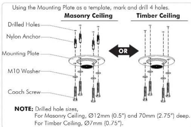
text_image
Using the Mounting Plate as a template, mark and drill 4 holes. Masonry Ceiling Drilled Holes Nylon Anchor Mounting Plate M10 Washer Coach Screw OR Timber Ceiling NOTE: Drilled hole sizes, For Masonry Ceiling, Ø12mm (0.5") and 70mm (2.75") deep. For Timber Ceiling, Ø7mm (0.75").Step 3. Install Mounting Cover

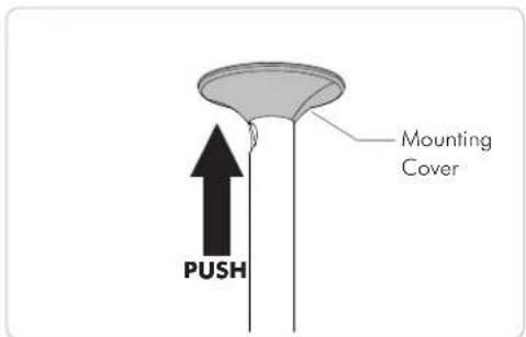
text_image
PUSH Pole Assembly Mounting CoverStep 4. Attach Pole Assembly to Base Plate
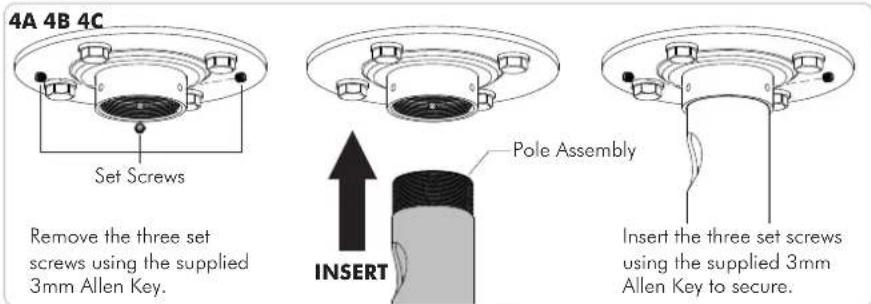
text_image
4A 4B 4C Set Screws Remove the three set screws using the supplied 3mm Allen Key. Pole Assembly INSERT Insert the three set screws using the supplied 3mm Allen Key to secure.Step 5. Position Mounting Cover
text_image
Mounting Cover PUSHStep 6. Set the Height of the Pole
6A

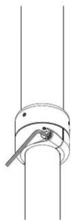
natural_image
Technical line drawing of a vertical pole with a magnified inset showing a mechanical component (no text or symbols)Whilst supporting the lower half of Pole Assembly loosen the Socket Cap Screws (x2) using the supplied 5mm Allen Key.
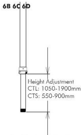
text_image
6B 6C 6D Height Adjustment CTL: 1050-1900mm CTS: 550-900mmSlide Pole Assembly to the desired height.
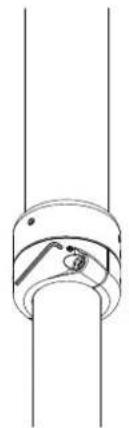
natural_image
Pure mechanical diagram showing a lever and shaft assembly without any text, numbers, or symbolsTighten the Socket Cap Screws (x2) to set the height using the supplied 5mm Allen Key.
natural_image
Pure mechanical diagram showing a cylindrical component with a flanged end and internal features (no text or symbols)If necessary, centralise the Pole Joint by tightening the Set Screws (x2) to suit using the 2.5mm Allen Key.
Step 7. Install the Ceiling Cover
If the lower pole hangs below a suspended ceiling, push the ceiling cover up to the ceiling.
Push up to the ceiling

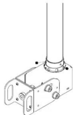
natural_image
Pure mechanical diagram of a vertical rod with a circular base and internal components, no text or symbols present.Step 8. Install the Clamp Head
8A 8B 8C

text_image
Set Screws ATTACHLoosen the three set screws using the supplied 3mm Allen Key.
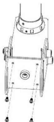
natural_image
Technical line drawing of a mechanical bracket assembly with mounting holes and a cylindrical component (no text or symbols)Secure the collar with the three set screws using the supplied 3mm Allen Key.
Step 9. Install the Horizontal Rail
9A. To Set Orientation
natural_image
Technical line drawing of a mechanical component with mounting holes and a central hub (no text or symbols)- Loosen the 4 screws using the supplied 2.5mm Allen Key.
NOTE: The rail mount is factory set in landscape orientation.
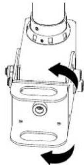
natural_image
Technical line drawing of a mechanical device with rotational arrows indicating motion (no text or symbols)- For Portrait orientation, rotate the head clamp 90° and insert the 4 screws again using the supplied 2.5mm Allen Key.

text_image
9B. Insert Horizontal Rail INSERT Horizontal Rail9C. Secure Horizontal Rail
- Make sure the large slot of Horizontal Rail is facing front.
- Align the holes of the Horizontal Rail and Head Clamp.
- Lock in place with M10 Screw and Washer using the supplied M8 Allen Key.

text_image
Large SlotStep 10. Install the Head Clamp Front Cover
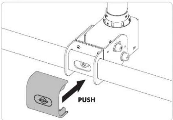
text_image
PUSHStep 11. Attach Mounting Brackets to the Display

text_image
The mounting brackets support hole configurations from 200-800mm in width to 200-500mm in height. TOP Display Mounting Screw (x4) Washer (x4) Mounting Bracket (x2) Back of Display Spacer (x4) (optional, use only for recessed mounting holes.)Step 12. Attach the Display to the Horizontal Rail

text_image
1. Hook the Display to the Horizontal Rail. 2. Slide sidewards to locate the centre. 3. Lock with the Bracket Locking Plate and M8x15mm screw. Use the supplied 8mm Allen Key to tighten firmly. 2. SLIDE 1. HOOK 3. LOCKStep 13. Tilt Adjustment

text_image
20° 10° Tighten M10 Bolts by using the supplied 8mm Allen Key paired with the required 17mm Socket Wrench.Step 14. Rotational Adjustment Step 15. Cable Management

text_image
360° Tightening Tool 360° Set Screw #1 Set Screw #2- To rotate the Display, loosen the set screw #1 using the supplied 2.5mm Allen Key and tighten to lock when desired orientation is achieved.
- Force adjustment is optional and to do this, loosen the set screw #2 using the supplied 2mm Allen Key, loosen or tighten the locking ring with the supplied tightening tool, and when the desired force is set, tighten the set screw.
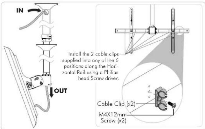
text_image
IN OUT Install the 2 cable clips supplied into any of the 6 positions along the Horizontal Rail using a Philips head Screw driver. Cable Clip (x2) M4X12mm Screw (x2)Step 16. Put on Clamp Covers Step 17. Store Supplied Allen Keys
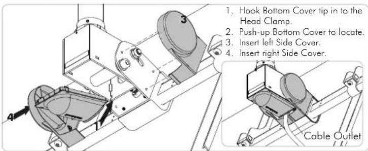
text_image
1. Hook Bottom Cover tip in to the Head Clamp. 2. Push-up Bottom Cover to locate. 3. Insert left Side Cover. 4. Insert right Side Cover. Cable Outlet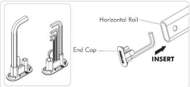
text_image
Horizontal Rail End Cap INSERTInstallation Complete