
SD-AT-DW-BK - Monitor Stand Atdec - Free user manual and instructions
Find the device manual for free SD-AT-DW-BK Atdec in PDF.


| Product Type | Monitor Stand |
| Brand | Atdec |
| Model | SD-AT-DW-BK |
| Color | Black |
| VESA Compatibility | 75x75mm, 100x100mm |
| Max Screen Size | 32 inches |
| Weight Capacity | 10 kg (22 lbs) |
| Material | Steel and Aluminum |
| Clamp Range | 10-85 mm |
| Grommet Range | 10-80 mm |
| Tilt Adjustment | -15° to +15° |
| Swivel Adjustment | ±45° |
| Rotation (Landscape/Portrait) | 90° |
| Height Adjustment Range | 200 mm (7.9 in) |
| Cable Management | Built-in clips |
| Mounting Options | Desk clamp or grommet |
| Dimensions (Stand Base) | 600 x 200 x 100 mm |
| Weight (Stand) | 2.5 kg (5.5 lbs) |
| Power Source | None (passive) |
| Compliance | TUV, GS certified |
| Maintenance | Clean with dry cloth; avoid solvents |
| Safety | Ensure clamp is securely tightened; do not exceed weight limit |
| Spare Parts | Contact Atdec support |
Frequently Asked Questions - SD-AT-DW-BK Atdec
User questions about SD-AT-DW-BK Atdec
0 question about this device. Answer the ones you know or ask your own.
Ask a new question about this device
Download the instructions for your Monitor Stand in PDF format for free! Find your manual SD-AT-DW-BK - Atdec and take your electronic device back in hand. On this page are published all the documents necessary for the use of your device. SD-AT-DW-BK by Atdec.
USER MANUAL SD-AT-DW-BK Atdec
Check you have received all parts against the Component Checklist above.
B Direct Wall Mount
Refer to Ergonomic guidelines overleaf to determine best position to mount wall bracket.

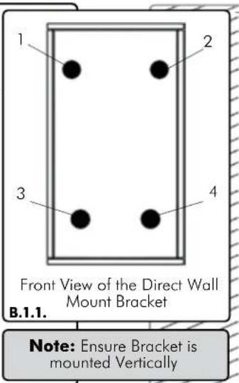

B.1. For Timber Stud Mounting - Use the Direct Wall Mount Bracket to mark out the location of the required four holes. (see diagram B.1.1.) Drill 4mm holes deep enough to receive the M6 Coach Screws, insert the screws and secure the bracket to the wall. (see diagram B.1.2.)
B.2. For Masonry Mounting - Use the Direct Wall Mount Bracket to mark the location of the required four holes. (see diagram B.1.1.) Using an 8mm masonry drill bit, drill four holes 41 mm deep. Insert the Nylon Anchors and then secure the Bracket to the wall using the M6 Coach Screws. (see diagram B.2.1.)
B Direct Wall Mount Continued.

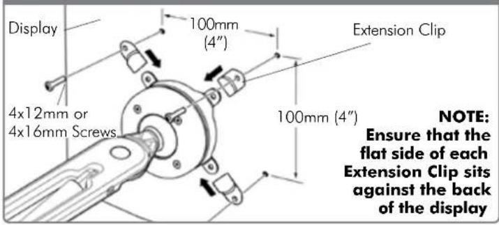
© Attaching the Display
75mm x 75mm (3" x 3") mounting hole pattern

100mm x 100mm (4" x 4") mounting hole pattern
(D) Installing Cable Management
D.1. Push the four supplied Cable Clips into the holes on the underside of the Wall Articulated Arm as shown.
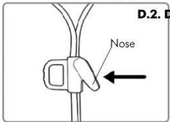
D.2. Feed the cables into the Cable Wrap Applicator.
D.3. Insert the Cable Wrap Applicator into the Cable Wrap as shown.
D.4. Squeeze the nose of the Applicator and place inside the Cable Wrap ensuring that the opening edges of the Cable Wrap face towards the nose of the applicator as shown in diagram.


natural_image
Illustration of hands using a tool to tie a rope or cable (no text or symbols visible)
natural_image
Illustration of hands tying a rope knot with a downward arrow (no text or symbols)E Attaching the Cable Wrap to the Arm
E.1. Position the display at its highest possible position to ensure that there is sufficient cabling at the end of the arm so the cables are not stretched or pulled out when the display is moved.

BEFORE PROCEEDING TO THE NEXT STEP PLEASE NOTE:
Wall Articulated Arm will only work when a display is properly installed.
DO NOT adjust tension screws or gas strut until your display has been attached.
Recommended Mounting Position
- When mounting the Spacedec Acrobat Wall Articulated Arm, ensure the correct focal distance can be achieved for ultimate visual comfort (Refer to Recommended Viewing Distance / Height below)

Recommended Viewing Distance / Height
- Ergonomists recommend that the optimal position of your screen should be slightly below eye level. When looking at the screen's centre the user should have a downward visual angle of approximately 10^ - 20^ . As a guide, the height (h) of your display should approximately be as follows:
- Tall Male (Max): 560mm (22") Tall Female (Max): 520mm (20 1/2")
- Short Male (Min): 368mm (14 1/2") Short Female (Min): 356mm (14")
- For visual comfort, a viewing distance (d) between 500mm (19 ^1/2 ") to 750mm (29 ^1/2 ") is recommended.
- Angular adjustments to reduce reflection on your monitor should range between 5° forward tilt to 15° backward tilt.

The Spacedec Acrobat Wall Articulated Arm comes factory set to support 6kg displays. Adjust the arm to suit the weight of your display as shown in the following steps:
G.1. Adjusting the Ball Joint Resistance
Depending on the weight of the display, it may be necessary to make adjustments to the Ball Joint Mechanism. If the display doesn't hold its position or is too resistant, adjust the four tension screws located around the Ball Joint (see diagram on the right) using the supplied 2.5mm Allen K _e
Check the display, and then adjust again if necessary.
NOTE: Be sure to adjust screws evenly.

G.2. Adjusting the Pivot Head Resistance
It is possible to control the amount of resistance in the Pivot Head to suit your display.
To increase the resistance of the Pivot Head to suit heavier displays, use the 5mm Allen Key supplied in the Desk Clamp Box to tighten the interscrew in a clockwise direction.
To decrease the resistance of the Pivot Head to suit lighter displays, loosen the interscrew in an anti-clockwise direction.
NOTE: It is recommended the Pivot Head be left at the factory setting for best performance.

G.3. Adjusting the Articulated Arm/Gas Strut Resistance
G.3.1. Depending on the weight of the display, it may be necessary to adjust the arm. This can be done by using the 5mm Allen Key supplied in the Desk Clamp Box.
G.3.2. If the arm tends to automatically rise or fall when the display is attached, it will be necessary to make small adjustments to the gas strut. (see diagram on the right)
G.3.3. If the arm tends to rise, the gas strut position should be raised. If the arm tends to fall, the gas strut position should be lowered.


- B Direct Wall Mount
- Installing Cable Management
- E Attaching the Cable Wrap to the Arm
- BEFORE PROCEEDING TO THE NEXT STEP PLEASE NOTE:
- Recommended Mounting Position
- Recommended Viewing Distance / Height
- G.1. Adjusting the Ball Joint Resistance
- G.2. Adjusting the Pivot Head Resistance
- G.3. Adjusting the Articulated Arm/Gas Strut Resistance
Brand : Atdec
Model : SD-AT-DW-BK
Category : Monitor Stand