
AWM-LR - Monitor Stand Atdec - Free user manual and instructions
Find the device manual for free AWM-LR Atdec in PDF.

| Product Type | Dual Monitor Stand |
| Brand | Atdec |
| Model | AWM-LR |
| Weight Capacity per Monitor | 2 - 7 kg (4.5 - 15 lbs) |
| Total Weight Capacity | Up to 14 kg (30 lbs) |
| VESA Compatibility | 75x75 mm, 100x100 mm |
| Number of Monitors Supported | 2 |
| Tilt Adjustment | Yes (ball joint, ±5° level) |
| Rotation | Yes (portrait orientation) |
| Cable Management | Yes |
| Mounting Type | Requires AWM Series arm (sold separately) |
| Tools Required | Phillips Head Screwdriver |
| Material | Steel |
| Color | Black |
| Included Components | Crossbar, VESA plates (2), handle (optional), hardware |
| Special Features | Adjustable ball joint tension, horizontal sliding, level adjustment |
| Safety Warning | Ensure monitor weight within range; curved and deep devices may exceed capacity |
| Maintenance | Wipe clean with dry cloth |
Frequently Asked Questions - AWM-LR Atdec
User questions about AWM-LR Atdec
0 question about this device. Answer the ones you know or ask your own.
Ask a new question about this device
Download the instructions for your Monitor Stand in PDF format for free! Find your manual AWM-LR - Atdec and take your electronic device back in hand. On this page are published all the documents necessary for the use of your device. AWM-LR by Atdec.
USER MANUAL AWM-LR Atdec
natural_image
Technical line drawing of a mechanical linkage system with mounting brackets and mounting feet (no text or symbols)COMPONENT CHECKLIST
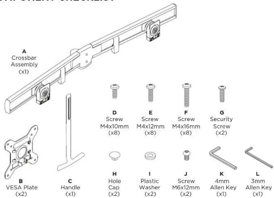

REQUIRED TOOLS
• Phillips Head Screwdriver
WEIGHT RANGE
2 - 7kg
(4.5 - 15lbs)
per monitor
Monitor weight should be within the weight range of all modular elements that make up the complete monitor mounting solution.
IMPORTANT INFORMATION
! Please ensure this product is installed as per these installation instructions.
! Curved monitors, deep devices (such as all-in-one PCs) and offset VESA locations exert additional leverage that can exceed the capacity of the mount even though the monitor weight may be within the stated range.
! The manufacturer accepts no responsibility for incorrect installation.
! This product is compatible with AWM Series monitor arm products.
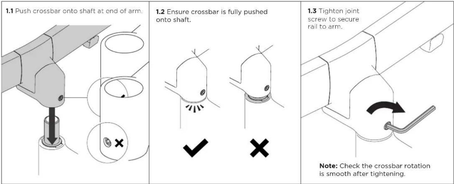
1. Mount crossbar onto arm
2. Attach handle (Optional)

3. Attach VESA plates to monitors
| 3.1 Screw VESA plates onto the monitors. | 3.2 Ensure suitable screw length is used. | 3.3 VESA mounting compatibility |
| OK Too short Too long ✓ ✗ ✗ ✗ | 100mm 75mm 100mm 75mm Note: For other sizes, use a suitable adaptor plate |
4. Mount monitors onto crossbar

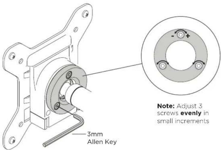
5. Adjust the ball joint tension
5.1 If the monitors are not holding position or are stiff to move, adjust the tension plate by tightening or loosening the three screws.
Note: Support the monitor while making adjustments.
6. Install Cables
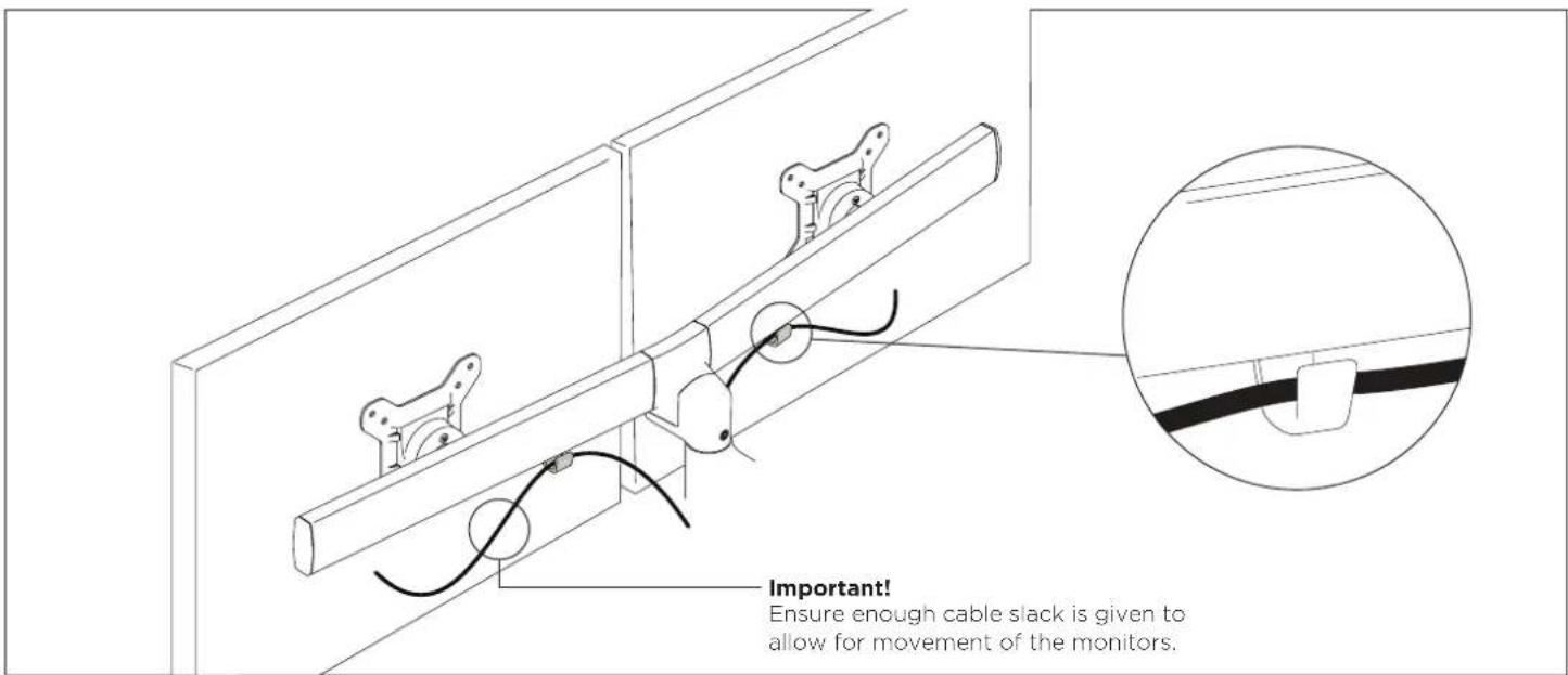
7. Adjust horizontal position of monitors
7.1 Slide the monitors along the crossbar until they are positioned centrally in the desired position.
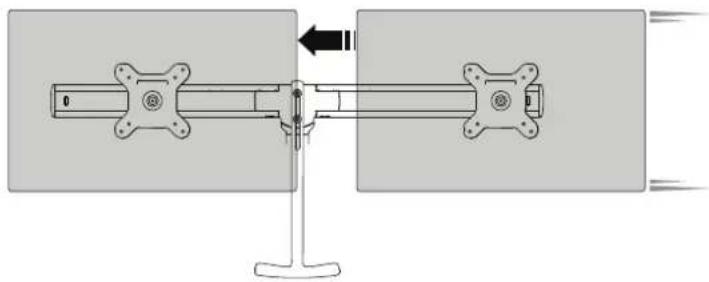
natural_image
Mechanical assembly diagram showing a shaft and housing with directional arrows (no text or symbols)7.2 Monitors can also be rotated to portrait position.

natural_image
Mechanical assembly diagram showing a shaft mounted on a stand with a curved arrow indicating rotation (no text or symbols present)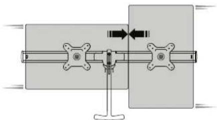
natural_image
Mechanical assembly diagram showing a shaft and flange with directional arrows indicating motion (no text or symbols)8. Adjust level of crossbar
8.1 Rotate the crossbar so that it sits parallel to the worksurface.
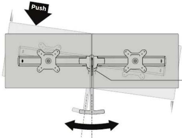
+/- 5°

OPTIONAL If the crossbar rotation is too loose or stiff, adjust the tension screw under the centre of the crossbar.
9. Adjust monitor angle
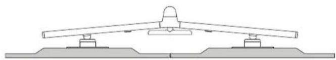
natural_image
Technical line drawing of a mechanical assembly with two supports and a central component (no text or symbols)ANGLEDFLAT

natural_image
Technical line drawing of a mechanical assembly with two flanged supports and a central hub (no text or symbols)
Brand : Atdec
Model : AWM-LR
Category : Monitor Stand