GZ-902 - Air conditioner Guzzanti - Free user manual and instructions
Find the device manual for free GZ-902 Guzzanti in PDF.


| Product Type | Portable Air Conditioner |
| Model | GZ-902 |
| Brand | Guzzanti |
| Operating Modes | Cool, Heat (on certain models), Dehumidify, Fan, Sleep, Auto |
| Temperature Range | 61°F - 88°F (adjustable) |
| Fan Speeds | High, Medium, Low |
| Timer | 1-24 hours (auto on/off) |
| Control | Control panel and remote control |
| Window Venting Kit | Included (fits windows up to 7 ft) |
| Exhaust Hose | Included |
| Internal Water Tank Capacity | 1.5 liters |
| Continuous Drain Port | Yes (garden hose not included) |
| Air Filter | Washable; clean every 2 weeks |
| Safety Features | Automatic shutoff when bucket full, compressor delay (3 min), child lock on remote |
| Power Cord | Do not use extension cord |
| Clearance Requirement | At least 10 inches (25 cm) around unit |
Frequently Asked Questions - GZ-902 Guzzanti
User questions about GZ-902 Guzzanti
0 question about this device. Answer the ones you know or ask your own.
Ask a new question about this device
Download the instructions for your Air conditioner in PDF format for free! Find your manual GZ-902 - Guzzanti and take your electronic device back in hand. On this page are published all the documents necessary for the use of your device. GZ-902 by Guzzanti.
USER MANUAL GZ-902 Guzzanti
natural_image
Simple line drawing of three horizontal rectangular panels with a rounded top and a small oval in the middle, labeled with number 15 (no text or symbols on panels)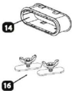
natural_image
Illustration of a mechanical component with two labeled parts (14 and 16), showing exploded and assembled views (no text or symbols beyond labels)
natural_image
Simple line drawing of a bracket and a screw (no text or symbols)natural_image
Line drawing of three rectangular objects with a handle and two small icons, no text or symbols presentVOLITELNÁ BEZPEČNOSTNÍ KONZOLA

natural_image
Three horizontal rectangular panels labeled A, B, C with a small inset image of two bird-shaped objects (no text or symbols)KŘÍDLOVÉ MATICE
natural_image
Simple line drawing of two rectangular compartments with internal oval shapes, no text or symbols presentnatural_image
Pure technical line drawing of a mechanical component with directional arrows, no text or symbols presentnatural_image
Pure technical line drawing of a mechanical joint or bracket (no text or symbols)natural_image
Diagram showing two car blocks on a surface with circular arrows indicating rotation (no text or symbols)natural_image
Line drawing of a window frame with a pair of scissors cutting a flat surface, no text or symbols present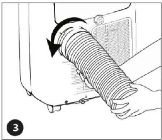
natural_image
Illustration of a hand holding a coiled hose with a black arrow indicating clockwise motion (no text or symbols)natural_image
Illustration of hands holding a coiled spring with a circular component, no text or symbols presentnatural_image
Line drawing of a small air conditioner unit with coiled tubing and control panel (no text or symbols)natural_image
Simple line drawing of a bracket and a screw (no text or symbols)Obr. 15.1
VYPRÁZDNĚNÍ VNITŘNÍHO ZÁSOBNÍKU VODY
natural_image
Symbol of a trash bin crossed with no text or numbers, representing waste sorting or restriction (no text present)


natural_image
Simple line drawing of three horizontal rectangular panels with a rounded top and a small oval in the middle, labeled with number 15 (no text or symbols on panels)
natural_image
Technical drawing of a bracket and screw assembly (no text or symbols)natural_image
Line drawing of a three-panel computer monitor with two small icons on top (no text or symbols)VOLITEĽNÁ BEZPEČNOSTNÁ KONZOLA


natural_image
Three horizontal rectangular panels labeled A, B, C with a small inset image of two bird-shaped objects (no text or symbols)KRÍDLOVÉ MATICE
natural_image
Simple line drawing of two rectangular compartments with internal oval shapes, no text or symbols presentnatural_image
Pure technical line drawing of a mechanical component with directional arrows, no text or symbols presentnatural_image
Pure technical line drawing of a mechanical joint or bracket (no text or symbols)natural_image
Diagram showing two car blocks with circular arrows indicating rotation or movement (no text or symbols)natural_image
Line drawing of a window frame with a pair of scissors cutting a flat surface, no text or symbols present
natural_image
Illustration of a hand holding a coiled hose with a black arrow indicating rotation (no text or symbols)natural_image
Illustration of hands holding a coiled spring with a circular component, no text or symbols presentnatural_image
Simple line drawing of a bracket and a screw (no text or symbols)Obr. 15.1
VYPRÁZDNENIE VNÚTORNÉHO ZÁSOBNÍKA VODY
natural_image
Symbol of a trash bin crossed with no text or numbers, representing waste sorting or disposal (no text present)
natural_image
Three horizontal rectangular panels labeled A, B, C with a small inset image of two bird-shaped objects (no text or symbols)natural_image
Simple line drawing of two rectangular compartments with internal oval shapes, no text or symbols presentnatural_image
Pure technical line drawing of a mechanical component with directional arrows, no text or symbols presentnatural_image
Pure technical line drawing of a mechanical joint or bracket (no text or symbols)natural_image
Diagram showing two car blocks on a surface with circular arrows indicating rotation (no text or symbols)natural_image
Line drawing of a window frame with a pair of clips and a separate clip holding scissors (no text or symbols)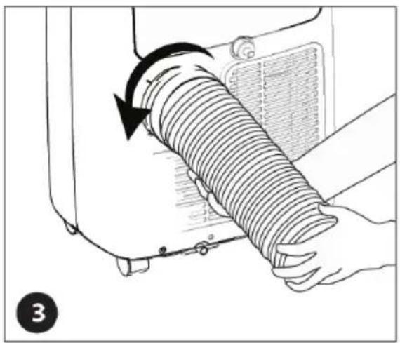
natural_image
Illustration of a hand holding a coiled hose with a black arrow indicating rotation (no text or symbols)natural_image
Illustration of hands holding a coiled spring with a circular arrow indicating rotation (no text or symbols)INSTALACJA STAŁEGO ODPŁYWU WODY:
Rys. 15.1
natural_image
Symbol of a trash bin crossed with no text or numbers, representing waste sorting or disposal (no text present)

natural_image
Line drawing of three rectangular objects with a handle and two small icons, no text or symbols presentOPCIONÁLIS BIZTONSÁGI KONZOL


natural_image
Simple line drawing of two rectangular compartments with internal oval shapes, no text or symbols presentnatural_image
Pure technical line drawing of a mechanical component with directional arrows, no text or symbols presentnatural_image
Pure technical line drawing of a mechanical joint or bracket (no text or symbols)natural_image
Diagram showing two car wheel positions on a conveyor belt, with rotation arrows indicating clockwise motion (no text or symbols)natural_image
Line drawing of a window frame with a pair of scissors cutting a flat surface, no text or symbols present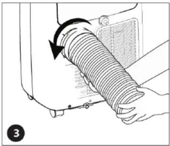
natural_image
Illustration of a hand holding a coiled industrial component with a black arrow indicating rotation (no text or symbols)natural_image
Illustration of hands holding a coiled spring with a circular component, no text or symbols presentnatural_image
Line drawing of a small air conditioner unit with coiled tubing and control panel (no text or symbols)natural_image
Technical drawing of a bracket and a screw (no text or symbols)15.1 ábra
A BELSŐ VÍZTARTÁLY KIÜRÍTÉSE
natural_image
Symbol of a trash bin crossed with no text or numbers, representing waste sorting or restriction (no text present)


natural_image
Simple line drawing of a bracket and a screw (no text or symbols)SESTAVNI DELI APARATA IN NAMESTITEV LE-TEH KOMPLET ZA OKNO

natural_image
Line drawing of a three-panel computer monitor with two small icons on top (no text or symbols)VOLITEĽNÁ BEZPEČNOSTNÁ KONZOLA
Varnostna konzola 1 vijak tipa B
MONTAŽA IN NAMESTITEV
natural_image
Simple line drawing of two rectangular compartments with internal oval shapes, no text or symbols present- Privijte krilno matico skupaj s podlago. NE ZATEGNITE krilnih matic popolnoma; naj bodo rahlo ohlapne.

natural_image
Pure technical diagram of a mechanical component with directional arrows, no text or symbols presentnatural_image
Pure technical line drawing of a mechanical joint or bracket (no text or symbols)natural_image
Diagram showing two car blocks on a slope with circular arrows indicating rotation (no text or symbols)- Montažo zaključite tako, da privijete predhodno nameščene krilne matice.
NAMESTITEV KOMPLETA ZA OKNO
PRENOSNA KLIMATSKA NAPRAVA
natural_image
Line drawing of a window frame with a pair of scissors cutting a flat surface, no text or symbols present
natural_image
Illustration of a hand holding a coiled industrial component with a black arrow indicating rotation (no text or symbols)natural_image
Illustration of hands holding a coiled spring with a circular arrow indicating rotation (no text or symbols)natural_image
Simple line drawings of a bracket and a screw (no text or symbols)Varnostna konzola 1 vijak tipa B
Enostavna in dvojna okna
Sl. 15.1
PRAZNJENJE NOTRANJEGA ZBIRALNIKA VODE
natural_image
Symbol of a trash bin crossed with no text or numbers, representing environmental protection (no text present)natural_image
Line drawing of a wooden door handle with a handle, two small icons on the left (no text or symbols)FAKULTATIVE SICHERHEITSKONSOLE

natural_image
Simple line drawing of two rectangular compartments with internal oval shapes, no text or symbols presentnatural_image
Pure technical line drawing of a mechanical component with directional arrows, no text or symbols presentnatural_image
Pure technical line drawing of a mechanical joint or bracket (no text or symbols)natural_image
Line drawing of a window frame and a pair of scissors cutting a flat panel (no text or symbols)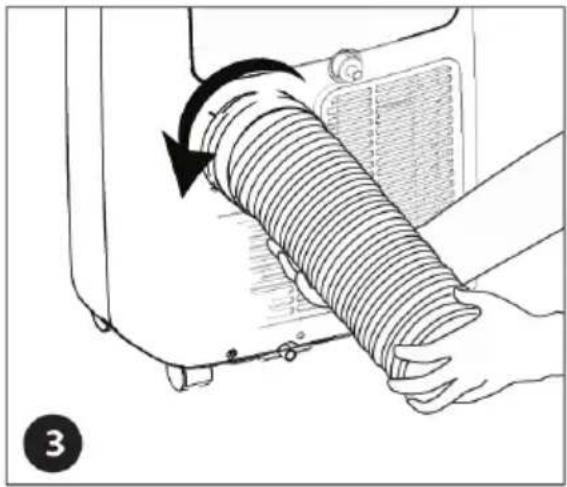
natural_image
Illustration of a hand holding a coiled hose with a valve, showing mechanical components and motion direction (no text or symbols)natural_image
Illustration of hands holding a coiled spring with a circular arrow indicating rotation (no text or symbols)natural_image
Technical drawing of a bracket and screw (no text or symbols)Abb. 15.1
AUSLEEREN DES VOLLEN WASSERBEHÄLTERS
natural_image
Symbol of a trash bin crossed with no text or numbers, representing waste sorting or disposal (no text present)
Portable Air conditioners are pieces of high value. In order to ensure your lawful rights and interests, please have the professional technicians to do the installation for you. This Instruction Manual is the universal-purpose version for the models of portable air conditioners manufactured by our Co. The appearance of the units that you purchase might be slightly different from the ones described in the Manual, but it does not affect your proper operations and usage.
Please read carefully the sections corresponding to the specific model you choose, and keep the Manual properly so as to facilitate your reference at later time.
ATTENTION:
Before installing and using your portable air conditioner, please read this owner's manual carefully. Store this manual in a safe place for future reference.
1) Always place the unit on a level surface.
2) Never use or store gasoline or other flammable vapor or liquid near this unit unless instructed by this manual.
3) Maintain at least 10 inches (25 cm) clearance space around this unit. Do not block or cover air inlet or outlet grilles.
4) The unit must be connected to a correctly grounded power supply.
5) Do not start or stop the unit by inserting or pulling out the power plug.
6) Do not use an adapter plug or extension cord.
7) Do not use the unit in the immediate surroundings of a bath, a shower or a swimming pool.
8) Do not insert anything into the air outlet. Do not obstruct air inlet or outlet grills unless instructed by this manual.
9) Do not let children play near this unit.
10) Always inspect the cord for signs of damage before use. If the power cord is damaged, it must be replaced by the manufacturer or a qualified service technician.
11) When cleaning the unit, always turn the unit off and unplug the power cord.
12) Do not mix old and new batteries in the remote control.
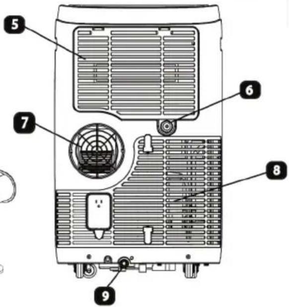
PRODUCT DIAGRAM
- Control Panel
- Manual Control Louver & Air Outlet
- Carry Handle
- Caster
- Air Filter
- Continuous Drain Port
- Hot Air Discharge Opening
- Air Intake Grille
- Condensation Drain Hole
- Exhaust Hose
- Exhaust Hose Connector
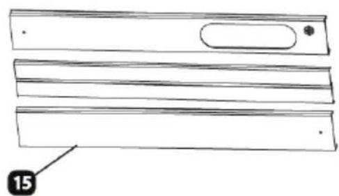
- Window Kit Adapter Grille
- Window Kit Adapter
- Optional Window Kit Adapter Extension
- Window Kit Panel
- Wing Nuts
- Optional Drain Tube
- Drain Tube Stopper
- Remote Control
- Battery
- Optional Window Security Pack
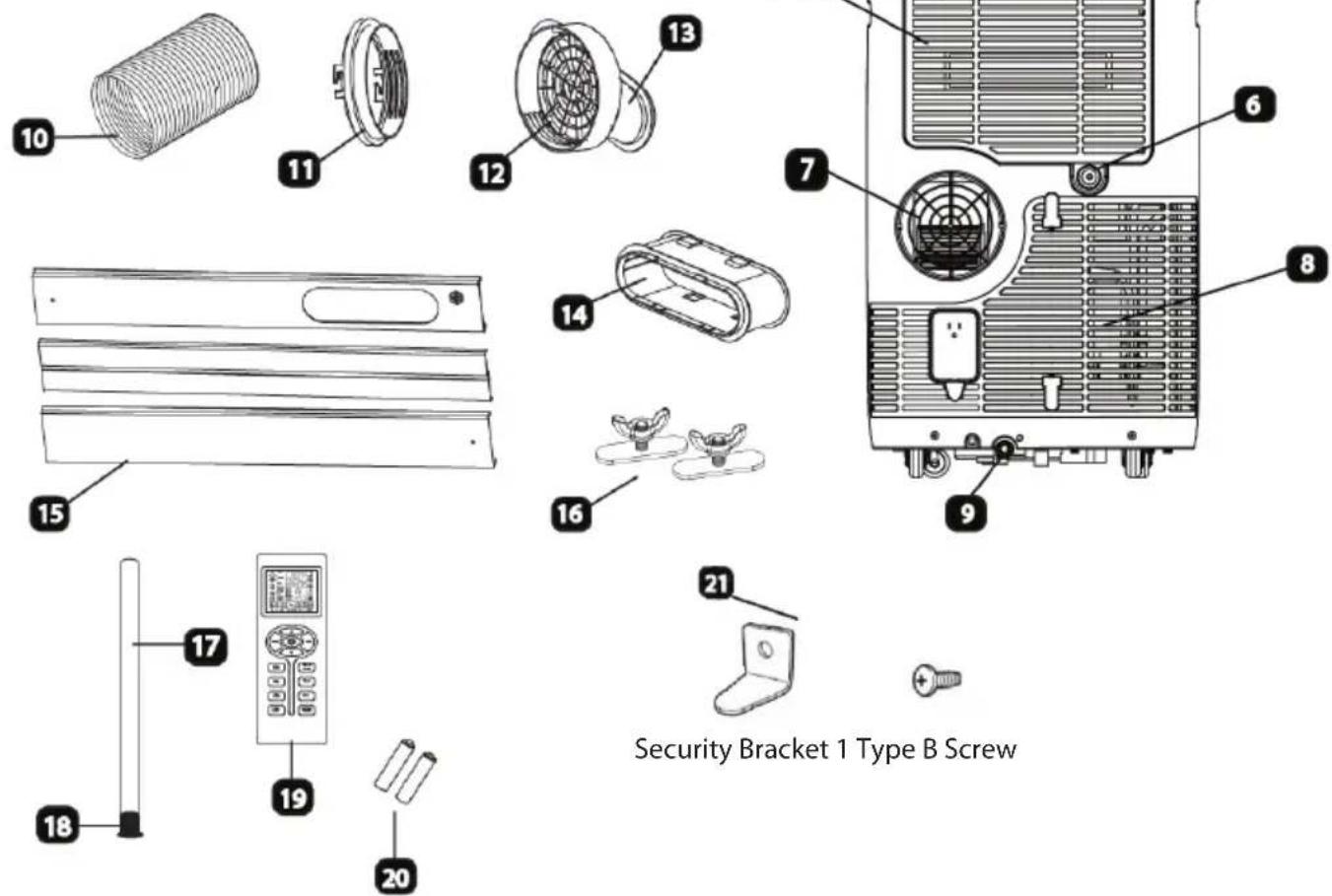

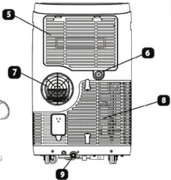

natural_image
Simple line drawing of a bracket and a screw (no text or symbols)PARTS AND ASSEMBLY
WINDOW VENTING KIT
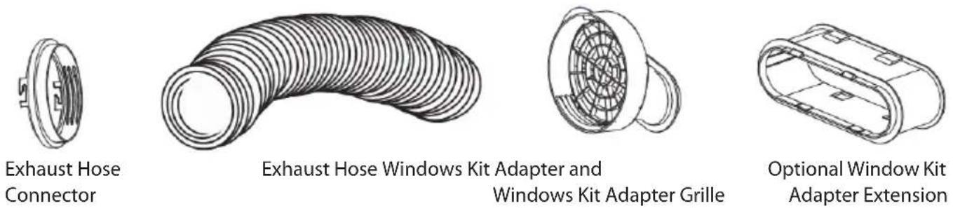

natural_image
Line drawing of three rectangular objects with a small inset image showing two small figures (no text or symbols)OPTIONAL WINDOW SECURITY BRACKET


Security Bracket 1 Type B Screw
ASSEMBLY & INSTALLATION
When the unit is operating in air conditioning mode, the unit draws in indoor air and exhausts hot air out of the room to complete the air exchange. The Window Kit must be installed when operating the unit in air conditioning, dehu-midification and heating modes. When the unit is operating in Fan Mode, no outdoor air exchange takes place. The window kit and exhaust hose do not need to be installed when the unit is used as a fan.
The supplied window kit can be installed in sliding windows and sliding glass doors up to 7 ft. long (approximate length). When installed, be sure to keep the exhaust hose and short and straight as possible for maximum efficiency.
WINDOW KIT ASSEMBLY
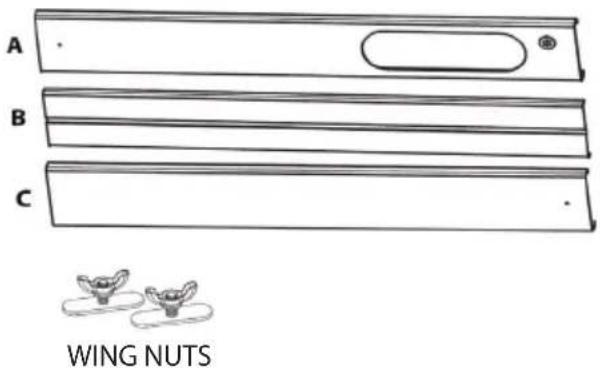
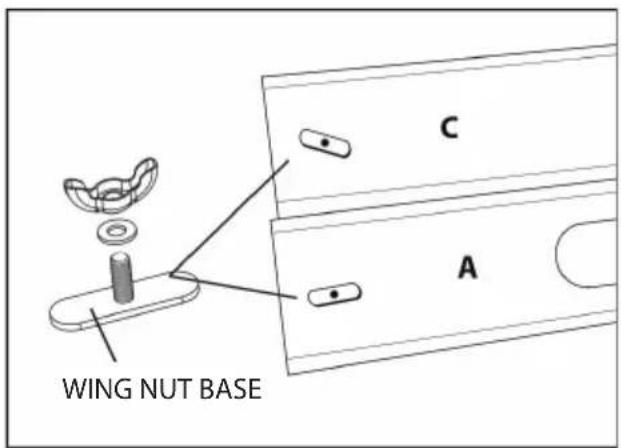
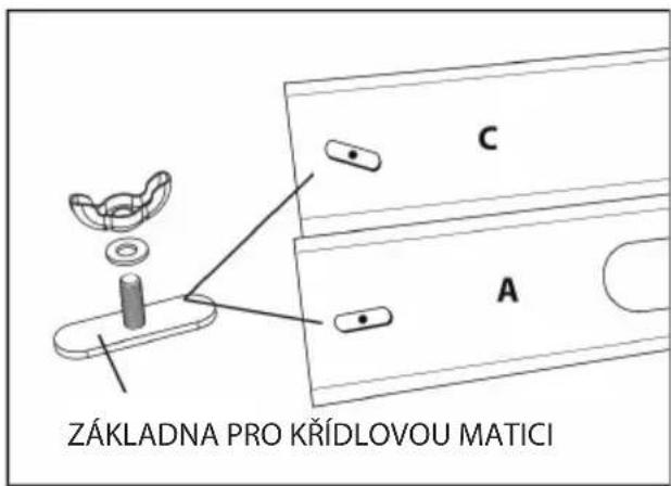
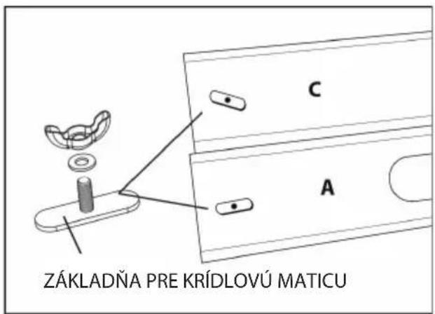
- Loose the Wing Nut and the Wing Nut Base, screw Wing nut into each of the small holes found on the Panel A and Panel C.

natural_image
Simple line drawing of two rectangular compartments with internal oval shapes, no text or symbols present- Tighten the Wing Nut with Wing Nut Base. DO NOT tighten the Wing Nuts all the way; makes sure they are somewhat loose.

natural_image
Pure technical line drawing of a mechanical component with directional arrows, no text or symbols present- Place the Panel B over the Wing Nut Base on Panel C.

natural_image
Pure technical line drawing of a mechanical component or bracket (no text or symbols)- Connect Panel A and C by placing the Panel B over the Wing Nut Base on Panel A.

- The Panel A and C should now be connected using the Panel B.

flowchart
graph TD
    A["Step 1"] --> B["Step 2"]
    B --> C["Feedback Loop"]
    style A fill:#f9f,stroke:#333
    style B fill:#bbf,stroke:#333
- To complet the assembly, tighten the Wing Nuts installed earlier.
WINDOW KIT INSTALLATION
PORTABLE AIR CONDITIONER
The window venting kit must be installed in order for the unit to work correctly. The window venting kit has been de-signed to fit into most vertical and horizontal window openings and sliding glass doors up to 7 feet.

natural_image
Line drawing of a window frame and a pair of scissors cutting a flat surface (no text or symbols)
natural_image
Illustration of a hand holding a coiled industrial hose with a valve, showing motion direction (no text or symbols)- Open the window or door to adjust the length of the Window Kit Panels to fit the opening. If necessary, mark the kit and cut one end down to properly fit the opening.
natural_image
Illustration of hands holding a coiled spring with a circular component, no text or symbols present-
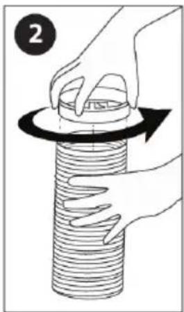
Twist the Exhaust Hose Connector onto Exhaust Hose.
-
Twist the Exhaust Hose Connector over the discharge opening on the back of the unit and extend the Exhaust Hose. (Keep the exhaust hose as short and straight as possible)

- Attach the Exhaust Hose to the Window Kit Adapter. Now connect the Optional Window Kit Adapter Extension to the Window Kit Adapter. Then attach the Optional Window Kit Adapter Extension to

SECURITY BRACKET
Optional Security Bracket Installation
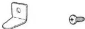
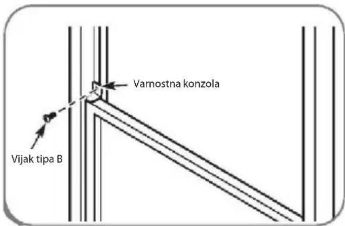
Your Window Kit also includes an optional security bracket that can be installed to prevent the window from being opened from the outside while a Window Kit is installed.

natural_image
Technical drawing of a bracket and screw (no text or symbols)Security Bracket 1 Type B Screw
Single and Double Hung Windows

Install the security bracket with a type B screw as shown if you need.
Sliding Windows

Install the window security bracket with a type B screw as shown.
CONTROL PANEL
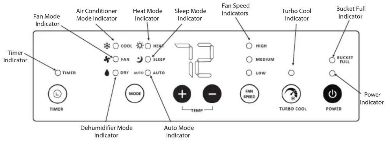
OPERATING INSTRUCTIONS FOR CONTROL PANEL BUTTONS
1) Power On and Off - Press the POWER button once to manually turn the unit on. Press the POWER button once more to turn the unit off.
2) Mode Selection - Press the MODE Button repeatedly to cycle between the different modes: Air Conditioner (Cool) mode, Fan-only mode, Dehumidifier (Dry) mode, Heat mode (cooling-only model without this mode), Sleep mode, and Auto mode. Each press of the MODE button will light up a different indicator on the control panel. The exhaust hose and window kit must be installed when the unit is in Air Conditioner, Heater, Dehumidifier mode, Auto mode, and Sleep mode. When using the unit as a fan, the window kit is not required.
3) Temperature - Select the desired temperature by pressing either the + or - button when using the unit in Air Conditioner or Heat mode. The temperature indicator flashes to display the desired temperature setting. After the temperature is set, the unit will display this temperature setting until it is changed by the user. The temperature indicator display shows temperature in Fahrenheit. While the unit is plugged in, but not powered on, press and hold the + and - buttons for 3 seconds to switch between Celsius and Fahrenheit.
4) Fan Speed - Press FAN SPEED button to choose fan speed in High, Medium or low.
5) Timer - Press TIMER button to set the unit automatically turn ON or OFF. Use the + and - buttons to program the hour increment.
6) Turbo Cool - When Turbo Cool is activated, the unit will cool at 61^ F on fan high for 10 minutes and then return to the original settings.
7) Bucket Full - When the unit cannot evaporate the collected moisture fast enough, the excess water will collect in a backup water tank located inside the unit. The BUCKET FULL indicator will light up.
8) Louver Direction - This unit has 2-way directional louvers. Use the louver guides manually to direct air up and down.
REMOTE CONTROL

1) Power On and Off - When the unit is plugged in, press the POWER ⏻ button to turn on the unit. Press the POWER button once more to turn the unit off. When in Air Conditioner mode, Heat mode, Auto mode, and Sleep mode, the selected temperature will appear on the remote control LCD display. When the unit is in Fan mode or Dehumidifier mode, no temperature will be displayed. This shows that temperature selection is not available when the unit is in Fan mode and Dehumidifier mode.
2) Mode Selection - Press the MODE Button repeatedly to cycle between the different modes: Auto, Sleep, Air Conditioner, Dehumidifier, Heat(cooling-only model without this mode), and Fan-Only mode. The mode icon on LCD display will light up showing which mode is selected.
3) Fan Speed - Press the FAN HIGH, FAN MED, or FAN LOW button to choose desired fan speed. When the unit is in Dehumidifier mode, the fan speed cannot be changed. When Turbo Cool is activated, fan speed is automatically set on high and is not adjustable in this mode.
4) Temperature Setting - When the unit is in Air Conditioner mode or Heat mode, you can select your desired temperature. Press the ▲ or ▼ to select your desired temperature setting. The temperature on the LCD display on the remote control will increase or decrease accordingly. Pressing the °C /°F button will switch the temperature select between °C and °F.
5) SLEEP MODE - When in air conditioning mode, press the SLEEP Button on the remote control, Sleep mode icon will show on the remote control LCD display. When in SLEEP mode, the fan will run on low to keep fan noise at a minimum. The temperature setting will gradually increase to 2°F above the original set temperature each of first 2 hours. The unit will keep operating the same temperature until the sleep mode is turned off.
6) TIMER -
Auto-On: Press the TIMER button when the unit is off to set up the Auto-on timer. The hour indicator on the LCD display will turn on. Press the TIMER button repeatedly to set timer within 1-24 hours.
Auto-Off: Press the TIMER button when the unit is On to set up the Auto-off timer. The hour indicator on the LCD display will turn on, Press the TIMER buttons to set timer within 1-24 hours. To cancel the timer, press the TIMER button until the timer mode is turned off.
7) TURBO COOL - Press the Turbo Cool button to activate Turbo Cool mode. The unit will cool at 61°F on fan high for 10 minutes and then return to the original settings. Fan speed is not adjustable in this mode.
NOTE: If Fan mode activates less than 3 minutes and switches to Turbo Cool, it will be a compressor protection shut down, compressor will turn on again until the 3 minutes is topped off. Switching from Heat or Auto mode to turbo cool is not allowed due to the protection of compressor.
8) MY TEMP MODE - Press this button to change the thermostat sensor from the air conditioner to the remote control location. The air conditioner will cool the area at the location and set temperature of the remote control.
9) CHILD LOCK- Press this button to lock/unlock the remote control buttons.
UNIT OPERATION
Air Conditioner Mode
1) Install the exhaust hose and window kit properly.
2) Plug the Power Cord into an electrical outlet.
3) Turn on the unit by pressing the POWER button.
4) Press the Mode button until the air conditioner mode indicator lights up on the control panel display.
5) Press the + or - until the desired room temperature appears on the control panel display. The temperature ranges from 61^ F - 88^ F.
6) Select the desired fan speed by pressing the FAN SPEED button.
NOTE: During hot days, the unit will cool the room most efficiently by setting the temperature at the low-est setting and the fan speed on high. Reducing the length of the exhaust duct, insulating the exhaust hose and window kit, and keeping direct sunlight to a minimum will also improve the cool-ing efficiency.
NOTE: When the unit is running on air conditioning mode, the exhaust hose is required and must be vented outside using the supplied window kit.
Heat Mode (cooling-only model without this mode)
1) Install the exhaust hose and window kit properly.
2) Plug the Power Cord into an electrical outlet.
3) Turn on the unit by pressing the POWER button.
4) Press the Mode button until the heat mode indicator lights up on the control panel display.
5) Press the + or - until the desired room temperature appears on the control panel display. The tempera-ture ranges from 61°F - 88°F.
6) Select the desired fan speed by pressing the FAN SPEED button.
NOTE: When the unit is running on Heat mode, the exhaust hose is required and must be vented outside using the supplied window kit.
NOTE: Switching from Heat mode to Turbo cool is not allowed due to the protection of compressor.
Dehumidifier Mode
1) Install the exhaust hose and window kit properly.
2) Plug the Power Cord into an electrical outlet.
3) Turn on the unit by pressing the POWER Button.
4) Press the MODE button until the dehumidifier mode indicator lights up on the control panel display.
5) Temperature indicator displays room temperature.
NOTE: The unit operates at low fan speed during dehumidifier mode. The unit cools room slightly during the dehumidification process. Keep the windows and doors closed to aid the effectiveness of the unit in removing the moisture from the room.
NOTE: When the unit is running on dehumidifier mode, the exhaust hose is required and must be vented outside using the supplied window kit.
NOTE: The unit will not perform in de-humidifier mode when the room temperature is lower than 50^ F.
Auto Mode
1) Install the exhaust hose and window kit properly.
2) Plug the Power Cord into an electrical outlet.
3) Turn on the unit by pressing the POWER button.
4) Press the MODE button until the Auto mode indicator lights up on the control panel display.
Auto Mode will operate the unit in air conditioning mode when the temperature is above 72 degrees, Fan mode when the temperature is below 72 degrees, and heating mode when the temperature is below 68 degrees.
NOTE: Switching from Auto mode to Turbo cool is not allowed due to the protection of compressor.
Sleep Mode
1) Install the exhaust hose and window kit properly.
2) Plug the Power Cord into an electrical outlet.
3) Turn on the unit by pressing the POWER button on the control panel.
4) Press the MODE button until the sleep mode indicator lights up on the control panel display.
NOTE: When in SLEEP mode, the fan will run on low to keep fan noise at a minimum. The temperature setting will gradually increase to 2^ F above the original set temperature each of first 2 hours. The unit will keep operating the same temperature until the sleep mode is turned off.
Fan Mode
1) Plug the Power Cord into an electrical outlet.
2) Turn on the unit by pressing the POWER button on the control panel.
3) Press the MODE button until the fan mode indicator lights up on the control panel display.
4) Select the fan speed by pressing the FAN SPEED button.
NOTE: It is not necessary for the exhaust hose and window kit to be installed to operate the unit in fan mode.
MAINTERANCE
BUCKET FULL INDICATOR
When the Internal Water Tank is full, the Bucket Full light will illuminate and the unit will automatically shut down. The air conditioner will resume normal operation once Internal Water Tank is emptied.
INTERNAL WATER TANK
When the room temperature is low and the indoor humidity is high, the air conditioner may not be able to evaporate some of the moisture fast enough. When this happens, the water will accumulate in an internal water tank inside the unit. The internal water tank holds approximately 1.5 liters of water. When this tanks becomes full, the unit will automatically shutdown and illuminate the Bucket Full indicator.
HOW TO INSTALL CONTINUOUS DRAIN OPTION:
- Place the Portable AC on a level surface.
- Remove the cap on continuous drain port on the back of the unit to access the Continuous Drain Port.
- Thread a garden hose (not supplied) onto the accessible Continuous Drain Port.
- Lead Garden Hose to a floor drain and cut to length.
- Make sure that there are no kinks or knots in the garden hose (Fig 15.1).
- Turn on the unit and gravity draining will begin automatically.
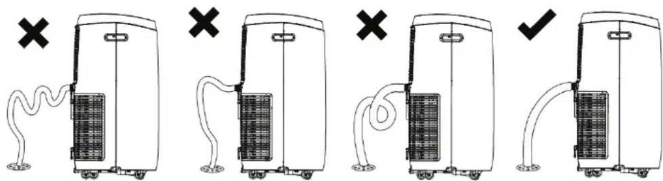
Fig. 15.1
HOW TO DRAIN THE INTERNAL WATER TANK
* You will need a small pan, approximately 1" high to catch the water coming out of the water tank. Once the water tank is empty, the unit will resume operation within a few minutes.
- Do not move the unit when the water container is full. (Water will spill out)
- Place a small pan under the condensation drain hole on the bottom side of the unit.
- Remove the drain plug from the condensation drain hole. The condensate water will drain out automati-cally.
- When the drain pan is full, install the drain plug back onto the condensation drain hole to stop the water flow.
- Empty the drain pan.
- Repeat steps 2-5 until all the water is emptied.
NOTE: Once the condensate tank has been emptied, firmly press the drain plug back onto the condensa-tion drain hole (Fig 16.1). It is not advised to use continuous drainage when the room temperature is higher than 90°F.

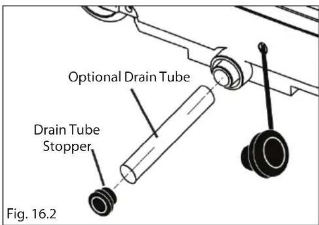
NOTE: You may also use enclosed Optional Drain Tube to facilitate the draining process, make sure to re-plug the Drain Stopper once the condensation tank has been emptied (Fig 16.2).
NOTE: Make sure power is off and the power cord is not plugged into an electrical outlet prior to performing any maintenance on the unit
Clean or replace filter - If the air filter is blocked with a dust, the airflow volume may reduce. It is recommended to clean the filter once every two weeks or as needed.
1) Remove the filter from the filter compartment on the back of the unit.
2) Wash the air filter by immersing it gently into warm water with a neutral detergent. Rinse the filter and dry it thoroughly out of sunlight.
3) Slide the filter back into the filter compartment after it is thoroughly dried.
4) If the filter is torn or unusable, order a new filter by calling the customer service number on the warranty page of this manual.
Clean the unit Housing
1) Keep the unit from being exposed directly to the sun to prevent color fading.
2) Clean the surface with a damp cloth and dry it with a soft towel.
Storing the Unit for an Extended Period of Time or Transporting the unit
1) Empty any excess water by unplugging the drain plug in the back of the unit (located at the bot-tom).
2) Unplug the unit.
3) The unit should be stored in a cool dry place.
TROUBLESHOOTING
TROUBLESHOOTING
| PROBLEM CAUSE SOLUTION | ||
| Air conditioner does not power on. | Unit is not plugged in.No electric current to outlet.Internal safety device has tripped. | Plug unit in.Check electric breaker box for a trip.Wait 30 minutes for safety device to reset. |
| Air conditioner works for a limited amount of time. | There are bends in the exhaust hose.Something is blocking the air from being discharged. | Position the air exhaust hose correctly, keeping it as short and free of curves as possible.Check and remove anything obstructing air discharge. |
| During operation, there is an unpleasant smell in the room. | Air filter is dirty. Remove air filters, clean and re-install. | |
| Air conditioner does not operate after restarting the unit. | The internal compressor safety device prevents the unit from being restarted until three minutes have elapsed since it was last turned off. | Wait for compressor to turn on. |
| The control panel display shows Error codes. | The unit has a self diagnosis system to identify a number of malfunctions. | See „Self-Diagnosis“. |
DISPOSAL OF USED ELECTRICAL AND ELECTRONIC EQUIPMENT

natural_image
Symbol of a trash bin crossed with no text or numbers, representing environmental restriction (no text present)This symbol on products or original documents means that used electric or electronic products must not be added to ordinary municipal waste. For proper disposal, renewal and recycling hand over these appliances to determined collection points. Alternatively, in some European Union states or other European countries you may return your appliances to the local retailer when buying an equivalent new appliance. Correct disposal of this product helps save valuable natural resources and prevents potential negative effects on the environment and human health, which could result from improper waste disposal. Ask your local authorities or collection facility for more details. In accordance with national regulations penalties may be imposed for the incorrect disposal of this type of waste.
For business entities in European Union states
If you want to dispose of electric or electronic appliances, ask your retailer or supplier for the necessary information.
Disposal in other countries outside the European Union.
This symbol is valid in the European Union. If you wish to dispose of this product, request the necessary information about the correct disposal method from the local council or from your retailer.
- VOLITELNÁ BEZPEČNOSTNÍ KONZOLA
- VYPRÁZDNĚNÍ VNITŘNÍHO ZÁSOBNÍKU VODY
- VOLITEĽNÁ BEZPEČNOSTNÁ KONZOLA
- VYPRÁZDNENIE VNÚTORNÉHO ZÁSOBNÍKA VODY
- INSTALACJA STAŁEGO ODPŁYWU WODY:
- OPCIONÁLIS BIZTONSÁGI KONZOL
- A BELSŐ VÍZTARTÁLY KIÜRÍTÉSE
- SESTAVNI DELI APARATA IN NAMESTITEV LE-TEH KOMPLET ZA OKNO
- MONTAŽA IN NAMESTITEV
- NAMESTITEV KOMPLETA ZA OKNO
- PRENOSNA KLIMATSKA NAPRAVA
- Enostavna in dvojna okna
- PRAZNJENJE NOTRANJEGA ZBIRALNIKA VODE
- FAKULTATIVE SICHERHEITSKONSOLE
- AUSLEEREN DES VOLLEN WASSERBEHÄLTERS
- ATTENTION:
- PRODUCT DIAGRAM
- PARTS AND ASSEMBLY
- WINDOW VENTING KIT
- OPTIONAL WINDOW SECURITY BRACKET
- ASSEMBLY & INSTALLATION
- WINDOW KIT ASSEMBLY
- WINDOW KIT INSTALLATION
- PORTABLE AIR CONDITIONER
- SECURITY BRACKET
- Optional Security Bracket Installation
- Single and Double Hung Windows
- CONTROL PANEL
- OPERATING INSTRUCTIONS FOR CONTROL PANEL BUTTONS
- REMOTE CONTROL
- UNIT OPERATION
- Air Conditioner Mode
- Heat Mode (cooling-only model without this mode)
- Dehumidifier Mode
- Auto Mode
- Sleep Mode
- Fan Mode
- MAINTERANCE
- BUCKET FULL INDICATOR
- INTERNAL WATER TANK
- HOW TO INSTALL CONTINUOUS DRAIN OPTION:
- HOW TO DRAIN THE INTERNAL WATER TANK
- Clean the unit Housing
- TROUBLESHOOTING
- DISPOSAL OF USED ELECTRICAL AND ELECTRONIC EQUIPMENT
- For business entities in European Union states
- Disposal in other countries outside the European Union.
Brand : Guzzanti
Model : GZ-902
Category : Air conditioner