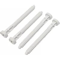
ZZ42BS - Uncategorized HAGER - Free user manual and instructions
Find the device manual for free ZZ42BS HAGER in PDF.


| Product Type | Electrical Distribution Enclosure (New VegaD series) |
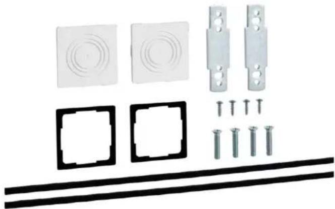
| Model Reference | ZZ42BS (door frame fixing plastic screws spare part) |
| Mounting Type | Surface or Flush |
| Protection Class | II (double insulated) |
| Ingress Protection | IP30 (without door), IP40/IP41 (with door) |
| Rated Voltage | 400/230 V AC, 50 Hz |
| Rated Current | Up to 160 A |
| Standards Compliance | EN/IEC 61439-1/-3, VDE 0660-600-1/-3, LCIE NF |
| Material | Halogen-free plastic (except PVC in label holders) |
| Surface Enclosure Sizes (Height x Width x Depth) | 450-1200 mm x 550 mm x 193 mm (various heights) |
| Flush Enclosure Sizes (Height x Width x Depth) | 537-1287 mm x 600 mm x 150/182 mm (low/high depth) |
| Weight (Surface, without door) | 6.0-16.2 kg (depending on height) |
| Weight (Flush, without door) | 7.5-20.2 kg (depending on height) |
| Key Features | Quick-Connect terminals, modular DIN rails, cable management accessories, multimedia options |
| Safety | IK08 with door, glow wire test 960°C for active parts |
| Installation | Wall-mounting (surface) or flush-mounting with plaster protection |
| Maintenance | Only qualified electricians; accessible components for inspection |
| Spare Parts Available | Yes, including ZZ42BS screw kit, doors, hinges, uprights, etc. |
| Reparability | Modular design allows easy replacement of internal units and accessories |
Frequently Asked Questions - ZZ42BS HAGER
User questions about ZZ42BS HAGER
0 question about this device. Answer the ones you know or ask your own.
Ask a new question about this device
Download the instructions for your Uncategorized in PDF format for free! Find your manual ZZ42BS - HAGER and take your electronic device back in hand. On this page are published all the documents necessary for the use of your device. ZZ42BS by HAGER.
USER MANUAL ZZ42BS HAGER
Technical Manual New VegaD
for surface-mounting flush-mounting & Accessories

natural_image
Exploded view of an open electrical cabinet showing internal components and wiring (no text or labels visible):hager
Table of contents
1 About this manual 4
1.1 Subject of the manual 5
1.2 Warranty and Liability 5
2 For your safety 6
2.1 Proper use 7
2.2 Requirements for authorised personnel 8
3 Product range by New VegaD surface 9
3.1 External dimensions 10
3.2 Market-specific product ranges 12
3.2.1 ACN Version 12
3.2.2 AN Version 13
3.2.3 BMN Version 14
3.2.4 BN Version 16
3.2.5 CN Version 17
3.2.6 DN Version 18
3.2.7 GN Version 19
3.2.8 LN Version 20
3.2.9 MN Version 21
3.2.10 RN Version 22
3.2.11 ZN Version 23
4 Product range by New VegaD flush
4.1 External dimensions 25
4.2 Market-specific product ranges 26
4.2.1 ACN Version 26
4.2.2 AN Version 27
4.2.3 BN Version 28
4.2.4 CN Version 29
4.2.5 DN Version 30
4.2.6 GN Version 31
4.2.7 LN Version 32
4.2.8 MN Version 33
4.2.9 RN Version 34
5 Doors for flush and surface enclosures
5.1 External dimensions 36
5.2 Door mounting into enclosure frames 38
5.3 Door hinges 39
6 Accessories
6.1 Naming rules 41
6.2 Equipment units 42
6.2.1 FD01.. = Equipment units, height 150 mm 42
6.2.2 FD02.. = Equipment units, height 300 mm 45
6.2.3 FD03.. = Equipment units, height 450 mm 51
6.3 Single and spare parts 52
6.3.1 FD00A... = Standard Accessories 52
6.3.2 FD00B... = Side Brackets for vertical cables 56
6.3.3 FD00C... = Covers 59
6.3.4 FD00M... = Mounting plates 61
6.3.5 FD00G... = Gallery Adapter for VegaD surface versions (FD...) 63
6.3.6 FD00F... = Fixation kit 71
6.3.7 FD00H... = DIN rail Holders for equipment units 81
6.3.8 FD00Q... = Quick-Connect & terminal holder 82
6.3.9 FD00P... = Plate for cable entry 83
6.3.10 FD00S... = Serrure (closing system) 89
6.3.11 FD00T... = Trunking 91
6.3.12 BA7A/HA7... = vertical trunkings sideways 93
6.3.13 FZ... = Univers cable storage and hiding box 94
6.3.14 UZ...V. = Univers N cable brackets 101
6.3.15 Door frames as spare parts 102
6.3.16 Vertical uprights and fixation accessories 104
7 Packaging and dimensions of enclosures 106
7.1 Pictures of packaging 107
7.2 Packaging use at the workshop or at the construction site 108
7.3 Labels 109
7.3.1 Labels on cardboard packaging 109
7.3.2 Enclosure type labels 109
7.4 Dimensions and weights of enclosures 110
7.4.1 Surface enclosures without door (FD...N) 110
7.4.2 Surface enclosures with door (FD...N) 111
7.4.3 Flush enclosures without door (FU...N) 112
7.4.4 Flush enclosures with door (FU...N) 113
8 Wall fixation 114
8.1 Wall-mounting for surface enclosures 115
8.2 Flush-mounting for flush enclosures 116
8.3 Plaster protection in flush enclosures 119
9 Technical data & certifications 121
9.1 Technical data 122
9.2 Power loss 123
9.2.1 Power loss for standard surface enclosures 123
9.2.2 Power loss for surface enclosures with ventilation openings FD00P5 123
9.2.3 Power loss for flush low-depth enclosures 124
9.2.4 Power loss for flush high-depth enclosures 124
9.3 Certifications 125
9.3.1 VDE certification for standard DIN/EN 61439-1/-3 125
9.3.2 VDE CB certification for standard IEC 61439-1/-3 126
9.3.3 LCIE certification for NF standard EN 61439-1/-3 127
9.3.4 VDE certification for standard DIN/EN/IEC 62208 for empty enclosures 128
10 List of References 129
11 Index 130
1 About this manual
These instructions are an integral part of the New VegaD enclosures.
Chapter index
Subject of the manual 5
Warranty and Liability 5
1.1 Subject of the manual
This document is intended for users of the flush- and surface-mounted New VegaD enclosures made by Hager. The instruction manual describes both the technology and the product ranges agreed with the respective markets, including accessories and spare parts required at the time of publication. In this manual, some features are described as an USP (Unique Selling Point) and indicate a clear product differentiation on the market at the time of publication. It provides also safety information for electrically skilled persons/the installer about the product's life cycle phases.
- Read and observe this manual before you start working on the enclosure or the switchgear and controlgear assembly.
- Also observe the supplied assembly manual for the respective enclosure or enclosure accessories.
- Store this manual and the assembly manuals in a safe place. The authorised personnel must have access to the manuals at all times.
As technical documentation, the manual should accompany the products described during their entire lifetime and is thus subject to periodical revisions, modifications and adjustments.
1.2 Warranty and Liability
These instructions do not extend the Sales and Delivery Conditions of Hager. No new claims concerning the warranty or guarantee, which extend beyond the Sales and Delivery Conditions, can be derived from this instruction manual.
Liability note
Hager reserves the right to modify or supplement the product or the documentation at any time without prior notice. Hager assumes no liability for typographical errors and any damage which may arise from them.
2 For your safety
- Avoid dangers. Adherence to the safety information in this section is a prerequisite for the safe assembly and use of the distribution board.
- Also observe the safety information provided in other sections.
Chapter index
Proper use 7
Requirements for authorised personnel 8
2.1 Proper use
The Hager New VegaD enclosure is a product offering for flush-mounted and surface installations, protected to IP30/40/41, for residential and commercial buildings with a maximum supply current of 160 A.
New VegaD flush enclosures are installed at a depth of 110 mm in the wall. They are available in 6 different heights and 2 different depths.
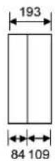
New VegaD surface enclosures are installed at a depth of 193 mm on the wall. They are available in 6 different heights.
The New VegaD enclosures have been equipped with components from the New VegaD internal fitting system.
Hager's tried and tested New VegaD enclosures and the New VegaD internal fitting system enable the implementation of switchgear and controlgear assemblies according to EN 61439 Part 3 (Distribution boards intended to be operated by ordinary persons / DBO).

Fixed indoor installation/wall mounting
With its enclosed design, the New VegaD enclosures are intended for stationary, indoor, surface- and flush-mounting in walls/hollow walls. The operating conditions for the indoor installation according to EN 61439 and the maximum ambient temperatures must be observed at the place of installation.
The New VegaD enclosures meet protection types IP30/IP40/IP41 when equipped with internal system and/or closed or slotted doors. The instructions in this manual regarding compliance with the protection type must be observed during installation works.
The New VegaD enclosures are available in protection class II (double insulated). The instructions in this manual regarding compliance with the protection type must be observed during installation works.
For more detailed information, refer to the technical data.
Intended use also includes:
- Reading and observing this manual, the installation manuals and the manuals for the internal fitting system
- Complying with the requirements for authorised personnel.
Misuse
Any other uses than those mentioned in this chapter as well as any modifications to the distribution enclosure are considered to be misuse. Hager does not assume any liability for damages resulting from misuse.
Limitation of operating areas
There are certain areas in which the New VegaD enclosure may not be used, in order to prevent hazards or damage to the enclosure.
The New VegaD is not suitable for use:
- in areas that require a higher protection type,
- in areas where ATEX directives must be observed,
- in operating sites at risk of fire,
- in corrosive environments. In particular, the enclosure and internal components can become damaged if used in chlorinated, sulphurous, acidic or saline environments.
2.2 Requirements for authorised personnel
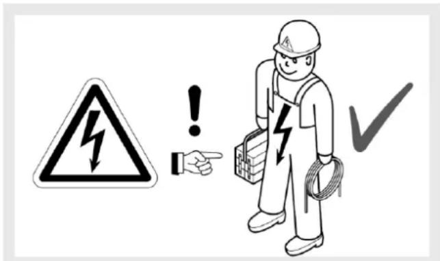
- Only qualified electrically skilled persons may assemble, install, commission switchgear and controlgear assemblies, perform extensions, troubleshooting or maintenance and disassemble and dispose of them.
- The qualified electrically skilled persons must have appropriate experience in initial testing and subsequent commissioning, troubleshooting and maintenance.
| Product life cycle phase | Minimum training, qualifications or competence |
| Planning | Electrically skilled person, consultant electrical engineer |
| Transport, assembly, installation | Electrically skilled person |
| Commissioning | Electrically skilled person with appropriate testing experience |
| Operation | Short-circuit devices for operation by ordinary persons inside distribution boards for operation by ordinary persons according to EN 61439-3 (DBO): Ordinary personsAll other components must be secured against use by ordinary persons. |
| Inspection and maintenance | Electrically skilled person with appropriate testing experience |
| Extensions | Electrically skilled person, planning and documentation required |
| Disassembly, disposal | Electrically skilled person, only for clearly defined mechanical and electrical work: electrically instructed person |
- An electrically skilled person by virtue of their professional training, skills and experience as well as knowledge of the relevant regulations can assess the work assigned to them and identify possible dangers.
- An electrically instructed person must be sufficiently informed and supervised by an electrically skilled person. The instructed person must thus be capable of identifying risks and avoiding dangers as well as dangers due to electricity.
- Anyone who is not an electrically skilled person or an electrically instructed person should always be considered as a non-professional, ordinary person. Non-professional, ordinary persons should never perform work in electrical systems independently or on their own authority. Non-professional, ordinary persons may only operate short-circuit devices intended for use by ordinary persons according to EN 61439-3.
3 Product range by New VegaD surface
Chapter index
External dimensions 10
Market-specific product ranges 12
3.1 External dimensions
FDX2 ACN / BN / CN / DN / LN / RN / ZN full equipped

[1] Between uprights
FDX2 AN / MN partly equipped

[1] Between uprights
FDX2 BMN partly equipped, Multimedia

[1] Between uprights
FDX2GN empty

[1] Between uprights
FDX2ZN tarif bleu triphasé
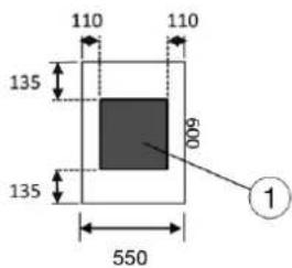

[1] French Platine Michaud 330 x 330 mm
3.2 Market-specific product ranges
3.2.1 ACN Version
- full equipped with transparent door
- door mounted-in
- with Quick-Connect terminals Green/Yellow
| Equipment standard | PEN QC holder 24 modules wide | Quick-Connect modules | Jumpers | Multi-functional side bracket for surface or flush | Instruction sheet with Quick-Connect explanation | Cover slot strip JP002 | 4 screws kit 4x16 for optional PEN holder or slider fixing | Plaster cardboard protection | DIN A4 label sheet with type sticker |
| FD22ACN | 1x | 1x KN26E | - | 4x | 1x | 1x | 1x | 1x | 1x |
| FD32ACN | 1x | 2x KN22E | 1x KN99E | 4x | 1x | 1x | 1x | 1x | 1x |
| FD42ACN | 1x | 1x KN22E / 1x KN26E | 1x KN99E | 4x | 1x | 1x | 1x | 1x | 1x |
| FD52ACN | 1x | 1x KN22E / 1x KN26E | 1x KN99E | 6x | 1x | 1x | 1x | 1x | 1x |
| FD62ACN | 2x | 3x KN26E | 2x KN99E | 6x | 1x | 1x | 1x | 1x | 1x |
| FD72ACN | 2x | 3x KN26E | 2x KN99E | 6x | 1x | 1x | 1x | 1x | 1x |

natural_image
Exterior view of a white electrical cabinet with multiple compartments and open door (no visible text or symbols)Example: FD52ACN
3.2.2 AN Version
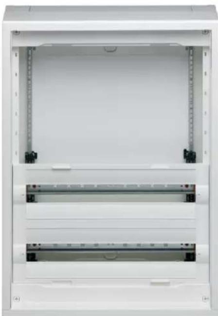
- partly equipped without door
- two first rows to complete
- with Quick-Connect terminals Green/Yellow
| Equipment standard | PEN QC holder 24 modules wide | Quick-Connect modules | Jumpers | Multi-functional side bracket for surface | Instruction sheet with Quick-Connect explanation | Cover slot strip JP002 | 4 screws kit 4x16 for optional PEN holder or slider fixing | 5 caps kit for covering wall-fixation screws | Paper cover marking strips 24 mod. and holder | Cable strain relief bar | Drawing map |
| FD22AN | 1x | 1x KN26E | - | - | 1x | 1x | 1x | 1x | - | 1x | 1x |
| FD32AN | 1x | 2x KN22E | 1x KN99E | 2x | 1x | 1x | 1x | 1x | 1x | 1x | 1x |
| FD42AN | 1x | 1x KN22E / 1x KN26E | 1x KN99E | 4x | 1x | 1x | 1x | 1x | 2x | 1x | 1x |
| FD52AN | 1x | 1x KN22E / 1x KN26E | 1x KN99E | 6x | 1x | 1x | 1x | 1x | 3x | 1x | 1x |
| FD62AN | 2x | 3x KN26E | 2x KN99E | 8x | 1x | 1x | 1x | 1x | 4x | 1x | 1x |
| FD72AN | 2x | 3x KN26E | 2x KN99E | 10x | 1x | 1x | 1x | 1x | 5x | 1x | 1x |
natural_image
Exterior view of a white electrical cabinet or enclosure with metal racks and ventilation grilles (no text or symbols visible)Example: FD42AN
3.2.3 BMN Version
- full equipped with plain door
- door mounted-in, door opening angle 135°
- with Quick-Connect terminal Green/Yellow
| Equipment standard | PEN QC holder 24 modules wide | Quick-Connect modules | DIN rails 24 modules | Front cover | Multi-functional side bracket for surface | Instruction sheet with 3 x socket outlet explanation | Cover slot strip JP002 | 4 screws kit 4x16 for optional PEN holder or slider fixing | 5 caps kit for covering wall-fixation screws | Paper cover marking strips 24 mod. and holder | Drawing map |
| FD42BMN | 1x | 1x KN06E | 1x | 1x FD00C4 | 2x | 1x | 1x | 1x | 1x | 1x | 1x |
| FD52BMN | 1x | 1x KN06E | 2x | 1x FD00C1 | 4x | 1x | 1x | 1x | 1x | 2x | 1x |
| (continuation) | Cable straps | Elastic strips | TV sticker | Aeration grid kit FD00P5 | Mounting plate FD00M1 | Cable bracket Univers | 35 x screw bag for Multi-media | Earthing cable for Multi-media | 3 x F-type Socket outlet VZ00ASF | Socket outlet mounting steel holder | Multimedia device starting kit 1 x TN003S + 1 x TN010S |
| FD42BMN | 4x | 4x | 1x | 1x | 2x | 6x | 1x | 1x | 1x | 1x | 1x |
| FD52BMN | 4x | 4x | 1x | 1x | 2x | 6x | 1x | 1x | 1x | 1x | 1x |

natural_image
Interior view of an open electrical enclosure with visible circuitry and panel switches (no text or symbols)Example: FD52BMN
Parts delivered-by in each BMN enclosure

Example of installation

natural_image
Interior view of an open electrical cabinet with open doors, showing internal components and a person in suit observing (no visible text or symbols)Example: standard enclosure FD42CN (left) associated with multimedia enclosure FD42BMN (right)
3.2.4 BN Version
- full equipped with plain door
- door mounted-in, door opening angle 135°
- with Quick-Connect terminals Green/Yellow
| Equipment standard | PEN QC holder 24 modules wide | Quick-Connect modules | Jumpers | Multi-functional side bracket for surface | Instruction sheet with Quick-Connect explanation | Cover slot strip JP002 | 4 screws kit 4x16 for optional PEN holder or slider fixing | 5 caps kit for covering wall-fixation screws | Paper cover marking strips 24 mod. and holder | Drawing map |
| FD22BN | 1x | 1x KN10E / 1x KN26E | 1x KN99E | 4x | 1x | 1x | 1x | 1x | 2x | 1x |
| FD32BN | 1x | 1x KN06E / 2x KN26E | 2x KN99E | 6x | 1x | 1x | 1x | 1x | 3x | 1x |
| FD42BN | 2x | 4x KN18E | 3x KN99E | 8x | 1x | 1x | 1x | 1x | 4x | 1x |
| FD52BN | 2x | 1x KN14E / 3x KN26E | 3x KN99E | 10x | 1x | 1x | 1x | 1x | 5x | 1x |
| FD62BN | 2x | 1x KN06E / 4x KN26E | 4x KN99E | 12x | 1x | 1x | 1x | 1x | 6x | 1x |
| FD72BN | 2x | 6x KN22E | 5x KN99E | 14x | 1x | 1x | 1x | 1x | 7x | 1x |

natural_image
Exterior view of a white electrical cabinet with open door (no visible text or symbols)Example: FD32BN
3.2.5 CN Version
- full equipped with transparent door
- door mounted-in, door opening angle 135°
- with Quick-Connect terminals Green/Yellow
| Equipment standard | PEN QC holder 24 modules wide | Quick-Connect modules | Jumpers | Multi-functional side bracket for surface | Instruction sheet with Quick-Connect explanation | Cover slot strip JP002 | 4 screws kit 4x16 for optional PEN holder or slider fixing | 5 caps kit for covering wall-fixation screws | Paper cover marking strips 24 mod. and holder | Drawing map |
| FD22CN | 1x | 1x KN10E / 1x KN26E | 1x KN99E | 4x | 1x | 1x | 1x | 1x | 2x | 1x |
| FD32CN | 1x | 1x KN06E / 2x KN26E | 2x KN99E | 6x | 1x | 1x | 1x | 1x | 3x | 1x |
| FD42CN | 2x | 4x KN18E | 3x KN99E | 8x | 1x | 1x | 1x | 1x | 4x | 1x |
| FD52CN | 2x | 1x KN14E / 3x KN26E | 3x KN99E | 10x | 1x | 1x | 1x | 1x | 5x | 1x |
| FD62CN | 2x | 1x KN06E / 4x KN26E | 4x KN99E | 12x | 1x | 1x | 1x | 1x | 6x | 1x |
| FD72CN | 2x | 6x KN22E | 5x KN99E | 14x | 1x | 1x | 1x | 1x | 7x | 1x |

natural_image
Exterior view of a white electrical cabinet with multiple compartments and open door (no visible text or symbols)Example: FD52CN
3.2.6 DN Version
- full equipped without door
- with Quick-Connect terminals Green/Yellow
| Equipment standard | PEN QC holder 24 modules wide | Quick-Connect modules | Jumpers | Multi-functional side bracket for surface | Instruction sheet with Quick-Connect explanation | Cover slot strip JP002 | 4 screws kit 4x16 for optional PEN holder or slider fixing | 5 caps kit for covering wall-fixation screws | Paper cover marking strips 24 mod. and holder | Cable strain relief bar | Drawing map |
| FD22DN | 1x | 1x KN26E | - | 4x | 1x | 1x | 1x | 1x | 2x | 1x | 1x |
| FD32DN | 1x | 2x KN22E | 1x KN99E | 6x | 1x | 1x | 1x | 1x | 3x | 1x | 1x |
| FD42DN | 1x | 1x KN22E / 1x KN26E | 1x KN99E | 8x | 1x | 1x | 1x | 1x | 4x | 1x | 1x |
| FD52DN | 1x | 1x KN22E / 1x KN26E | 1x KN99E | 10x | 1x | 1x | 1x | 1x | 5x | 1x | 1x |
| FD62DN | 2x | 3x KN26E | 2x KN99E | 12x | 1x | 1x | 1x | 1x | 6x | 1x | 1x |
| FD72DN | 2x | 3x KN26E | 2x KN99E | 14x | 1x | 1x | 1x | 1x | 7x | 1x | 1x |

natural_image
Front view of an open electrical cabinet with multiple horizontal panels and indicator lights (no visible text or symbols)Example: FD42DN
3.2.7 GN Version
- empty without door
- without Quick-Connect terminals
| Equipment delivered-by | PEN QC holder 24 modules wide | Instruction sheet with Quick-Connect explanation | 4 screws kit 4x16 for optional PEN holder or slider fixing | 5 caps kit for covering wall-fixation screws |
| FD22GN | 1x | 1x | 1x | 1x |
| FD32GN | 1x | 1x | 1x | 1x |
| FD42GN | 1x | 1x | 1x | 1x |
| FD52GN | 1x | 1x | 1x | 1x |
| FD62GN | 2x | 1x | 1x | 1x |
| FD72GN | 2x | 1x | 1x | 1x |

natural_image
Exterior view of a white industrial electrical cabinet frame with mounting holes and ventilation slots (no text or symbols visible)Example: FD42GN
3.2.8 LN Version
- full equipped without door
- without Quick-Connect terminals
| Equipment standard | PEN QC holder 24 modules wide | Multi-functional side bracket surface or flush | Instruction sheet w /o Quick-Connect explanation | Cover slot strip JP002 | 4 screws kit 4x16 for optional PEN holder or slider fixing | 5 caps kit for covering wall-fixation screws | Paper cover marking strips 24 mod. and holder |
| FD22LN | 1x | 4x | 1x | 1x | 1x | 1x | 2x |
| FD32LN | 1x | 6x | 1x | 1x | 1x | 1x | 3x |
| FD42LN | 1x | 8x | 1x | 1x | 1x | 1x | 4x |
| FD52LN | 1x | 10x | 1x | 1x | 1x | 1x | 5x |
| FD62LN | 2x | 12x | 1x | 1x | 1x | 1x | 6x |
| FD72LN | 2x | 14x | 1x | 1x | 1x | 1x | 7x |

natural_image
Front view of a white electrical cabinet with multiple horizontal panels and control buttons (no visible text or symbols)Example: FD42LN
3.2.9 MN Version
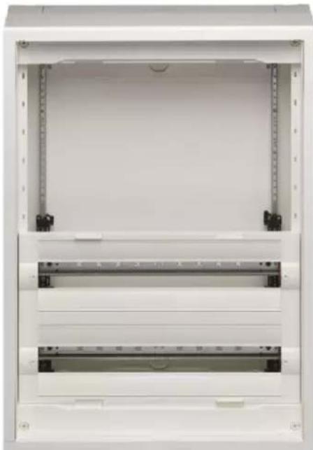
- partly-equipped without door
- two first rows to complete
- with Quick-Connect terminals Green/Yellow & Blue
| Equipment standard | PEN QC holder 24 modules wide | Quick-Connect modules | Jumpers | Multi-functional side bracket for surface | Instruction sheet with Quick-Connect explanation | Cover slot strip JP002 | 4 screws kit 4x16 for optional PEN holder or slider fixing | 5 caps kit for covering wall-fixation screws | Paper cover marking strips 24 mod. and holder |
| FD22MN | 1x | 1x KN10N / 1x KN10E | - | - | 1x | 1x | 1x | 1x | - |
| FD32MN | 1x | 1x KN18N / 1x KN18E | - | 2x | 1x | 1x | 1x | 1x | 1x |
| FD42MN | 1x | 1x KN22N / 1x KN22E | - | 4x | 1x | 1x | 1x | 1x | 2x |
| FD52MN | 1x | 1x KN26N / 1x KN26E | - | 6x | 1x | 1x | 1x | 1x | 3x |
| FD62MN | 2x | 2x KN18N / 2x KN18E | 1x KN99N / 1x KN99E | 8x | 1x | 1x | 1x | 1x | 4x |
| FD72MN | 2x | 2x KN18N / 2x KN18E | 1x KN99N / 1x KN99E | 10x | 1x | 1x | 1x | 1x | 5x |
natural_image
Exterior view of a white electrical cabinet or enclosure with metal brackets and ventilation slots (no text or symbols visible)Example: FD42MN
3.2.10 RN Version
- full equipped without door
- with Quick-Connect terminals Green/Yellow & Blue
| Equipment standard | PEN QC holder 24 modules wide | Quick-Connect modules | Jumpers | Multi-functional side bracketsurface or flush | Instruction sheet with Quick-Connect explanation | Cover slot strip JP002 | 4 screws kit 4x16 for optional PEN holder or slider fixing | 5 caps kit for covering wall-fixation screws (FD versions only) | Paper cover marking strips 24 mod. and holder |
| FD22RN | 1x | 1x KN10N / 1x KN10E | - | 4x | 1x | 1x | 1x | 1x | 2x |
| FD32RN | 1x | 1x KN18N / 1x KN18E | - | 6x | 1x | 1x | 1x | 1x | 3x |
| FD42RN | 1x | 1x KN22N / 1x KN22E | - | 8x | 1x | 1x | 1x | 1x | 4x |
| FD52RN | 1x | 1x KN26N / 1x KN26E | - | 10x | 1x | 1x | 1x | 1x | 5x |
| FD62RN | 2x | 2x KN18N / 2x KN18E | 1x KN99N / 1x KN99E | 12x | 1x | 1x | 1x | 1x | 6x |
| FD72RN | 2x | 2x KN18N / 2x KN18E | 1x KN99N / 1x KN99E | 14x | 1x | 1x | 1x | 1x | 7x |

natural_image
Front view of a white server rack cabinet with multiple drive bays and indicator lights (no visible text or labels)Example: FD72RN
3.2.11 ZN Version
- equipped with French platine kit Tarif bleu triphasé without door
| Equipment standard | Kit Michaud Platine 330x300 with cover | Instruction sheet with Quick-Connect explanation | 4 screws kit 4x16 for optional PEN holder or slider fixing | 5 caps kit for covering wall-fixation screws | Paper cover marking strips 24 mod. Univers |
| FD32ZN | 1x | 1x | 1x | 1x | 1x |

natural_image
Exterior view of a white electrical enclosure with internal compartments and mounting holes (no text or symbols visible)Example: FD32ZN
4 Product range by New VegaD flush
Chapter index
External dimensions 25
Market-specific product ranges 26
4.1 External dimensions
FUX2 ACN / BN / CN / DN / LN / RN full equipped
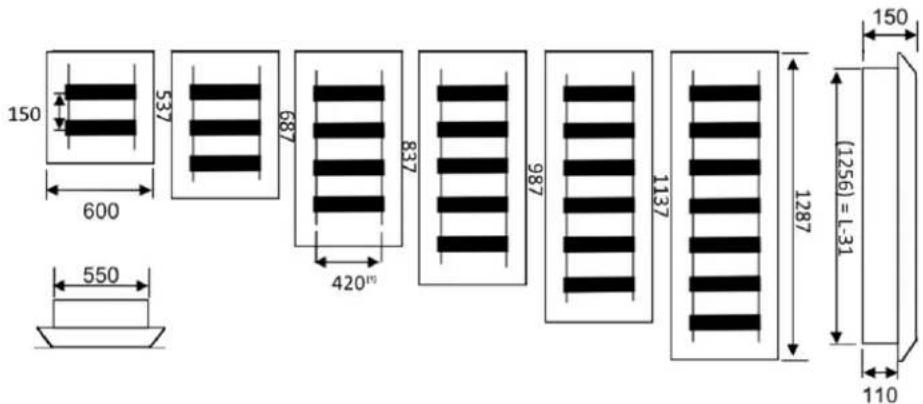
[1] Between uprights
FUX2 AN / MN partly equipped

[1] Between uprights
FUX2GN empty

[1] Between uprights
4.2 Market-specific product ranges
4.2.1 ACN Version
- full equipped with transparent door
- door mounted-in
- with Quick-Connect terminals Green/Yellow
| Equipment standard | PEN QC holder 24 modules wide | Quick-Connect modules | Jumpers | Side cable bracket for flush | Instruction sheet with Quick-Connect explanation | Cover slot strip JP002 | 4 screws kit 4x16 for optional PEN holder or slider fixing | Plaster cardboard protection | DIN A4 label sheet with type sticker |
| FU22ACN | 1x | 1x KN26E | - | 4x | 1x | 1x | 1x | 1x | 1x |
| FU32ACN | 1x | 2x KN22E | 1x KN99E | 4x | 1x | 1x | 1x | 1x | 1x |
| FU42ACN | 1x | 1x KN22E / 1x KN26E | 1x KN99E | 4x | 1x | 1x | 1x | 1x | 1x |
| FU52ACN | 1x | 1x KN22E / 1x KN26E | 1x KN99E | 6x | 1x | 1x | 1x | 1x | 1x |
| FU62ACN | 2x | 3x KN26E | 2x KN99E | 6x | 1x | 1x | 1x | 1x | 1x |
| FU72ACN | 2x | 3x KN26E | 2x KN99E | 6x | 1x | 1x | 1x | 1x | 1x |

natural_image
White open refrigerator cabinet with multiple compartments (no visible text or labels)Example: FU52ACN
4.2.2 AN Version
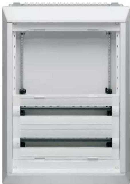
- partly equipped without door
- two first rows to complete
- with Quick-Connect terminals Green/Yellow
- flush high-depth version
| Equipment standard | PEN QC holder 24 modules wide | Quick-Connect modules | Jumpers | Side cable bracket for flush | Instruction sheet with Quick-Connect explanation | Cover slot strip JP002 | 4 screws kit 4x16 for optional PEN holder or slider fixing | Plaster cardboard protection | Paper cover marking strips 24 mod. and holder | Cable strain relief bar |
| FU22AN | 1x | 1x KN26E | - | - | 1x | 1x | 1x | 1x | - | 1x |
| FU32AN | 1x | 2x KN22E | 1x KN99E | 2x | 1x | 1x | 1x | 1x | 1x | 1x |
| FU42AN | 1x | 1x KN22E / 1x KN26E | 1x KN99E | 4x | 1x | 1x | 1x | 1x | 2x | 1x |
| FU52AN | 1x | 1x KN22E / 1x KN26E | 1x KN99E | 6x | 1x | 1x | 1x | 1x | 3x | 1x |
| FU62AN | 2x | 3x KN26E | 2x KN99E | 8x | 1x | 1x | 1x | 1x | 4x | 1x |
| FU72AN | 2x | 3x KN26E | 2x KN99E | 10x | 1x | 1x | 1x | 1x | 5x | 1x |
natural_image
Exterior view of a white electrical cabinet or enclosure with multiple horizontal panels and mounting feet (no visible text or symbols)Example: FU42AN
4.2.3 BN Version
- full equipped with plain door
- door mounted-in
- with Quick-Connect terminals Green/Yellow
| Equipment standard | PEN QC holder 24 modules wide | Quick-Connect modules | Jumpers | Side cable bracket for flush | Instruction sheet with Quick-Connect explanation | Cover slot strip JP002 | 4 screws kit 4x16 for optional PEN holder or slider fixing | Plaster cardboard protection | Paper cover marking strips 24 mod. and holder | Drawing map |
| FU22BN | 1x | 1x KN10E / 1x KN26E | 1x KN99E | 4x | 1x | 1x | 1x | 1x | 2x | 1x |
| FU32BN | 1x | 1x KN06E / 2x KN26E | 2x KN99E | 6x | 1x | 1x | 1x | 1x | 3x | 1x |
| FU42BN | 2x | 4x KN18E | 3x KN99E | 8x | 1x | 1x | 1x | 1x | 4x | 1x |
| FU52BN | 2x | 1x KN14E / 3x KN26E | 3x KN99E | 10x | 1x | 1x | 1x | 1x | 5x | 1x |
| FU62BN | 2x | 1x KN06E / 4x KN26E | 4x KN99E | 12x | 1x | 1x | 1x | 1x | 6x | 1x |
| FU72BN | 2x | 6x KN22E | 5x KN99E | 14x | 1x | 1x | 1x | 1x | 7x | 1x |

natural_image
White open electrical cabinet with multiple internal compartments (no visible text or symbols)Example: FU52BN
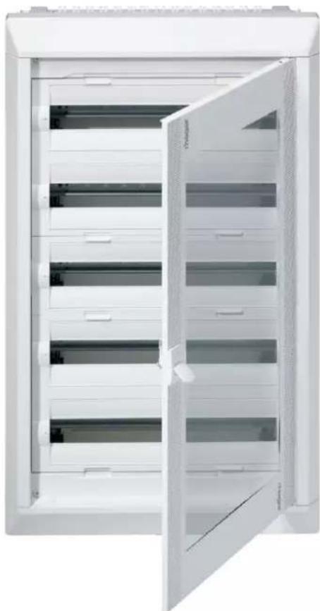
4.2.4 CN Version
- full equipped with transparent door
- door mounted-in
- with Quick-Connect terminals Green/Yellow
| Equipment standard | PEN QC holder 24 modules wide | Quick-Connect modules | Jumpers | Side cable bracket for flush | Instruction sheet with Quick-Connect explanation | Cover slot strip JP002 | 4 screws kit 4x16 for optional PEN holder or slider fixing | Plaster cardboard protection | Paper cover marking strips 24 mod. and holder | Drawing map |
| FU22CN | 1x | 1x KN10E / 1x KN26E | 1x KN99E | 4x | 1x | 1x | 1x | 1x | 2x | 1x |
| FU32CN | 1x | 1x KN06E / 2x KN26E | 2x KN99E | 6x | 1x | 1x | 1x | 1x | 3x | 1x |
| FU42CN | 2x | 4x KN18E | 3x KN99E | 8x | 1x | 1x | 1x | 1x | 4x | 1x |
| FU52CN | 2x | 1x KN14E / 3x KN26E | 3x KN99E | 10x | 1x | 1x | 1x | 1x | 5x | 1x |
| FU62CN | 2x | 1x KN06E / 4x KN26E | 4x KN99E | 12x | 1x | 1x | 1x | 1x | 6x | 1x |
| FU72CN | 2x | 6x KN22E | 5x KN99E | 14x | 1x | 1x | 1x | 1x | 7x | 1x |
natural_image
Exterior view of a white electrical cabinet with multiple compartments and open door (no text or symbols visible)Example: FU52CN
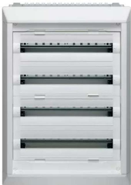
4.2.5 DN Version
- full equipped without door
- with Quick-Connect terminals Green/Yellow
| Equipment standard | PEN QC holder 24 modules wide | Quick-Connect modules | Jumpers | Side cable bracket for flush | Instruction sheet with Quick-Connect explanation | Cover slot strip JP002 | 4 screws kit 4x16 for optional PEN holder or slider fixing | Plaster cardboard protection | Paper cover marking strips 24 mod. and holder |
| FU22DN | 1x | 1x KN26E | - | 4x | 1x | 1x | 1x | 1x | 2x |
| FU32DN | 1x | 2x KN22E | 1x KN99E | 6x | 1x | 1x | 1x | 1x | 3x |
| FU42DN | 1x | 1x KN22E / 1x KN26E | 1x KN99E | 8x | 1x | 1x | 1x | 1x | 4x |
| FU52DN | 1x | 1x KN22E / 1x KN26E | 1x KN99E | 10x | 1x | 1x | 1x | 1x | 5x |
| FU62DN | 2x | 3x KN26E | 2x KN99E | 12x | 1x | 1x | 1x | 1x | 6x |
| FU72DN | 2x | 3x KN26E | 2x KN99E | 14x | 1x | 1x | 1x | 1x | 7x |
natural_image
Front view of a white electrical cabinet with multiple horizontal panels and ventilation slots (no visible text or symbols)Example: FU42DN
4.2.6 GN Version
- empty without door
- without Quick-Connect terminals
- flush high-depth version
| Equipment standard | PEN QC holder 24 modules wide | Instruction sheet with Quick-Connect explanation | 4 screws kit 4x16 for optional PEN holder or slider fixing | Plaster cardboard protection |
| FU22GN | 1x | 1x | 1x | 1x |
| FU32GN | 1x | 1x | 1x | 1x |
| FU42GN | 1x | 1x | 1x | 1x |
| FU52GN | 1x | 1x | 1x | 1x |
| FU62GN | 2x | 1x | 1x | 1x |
| FU72GN | 2x | 1x | 1x | 1x |

natural_image
Exterior view of a white rectangular office space with vertical metal bars and mounting brackets (no text or symbols visible)Example: FU42GN
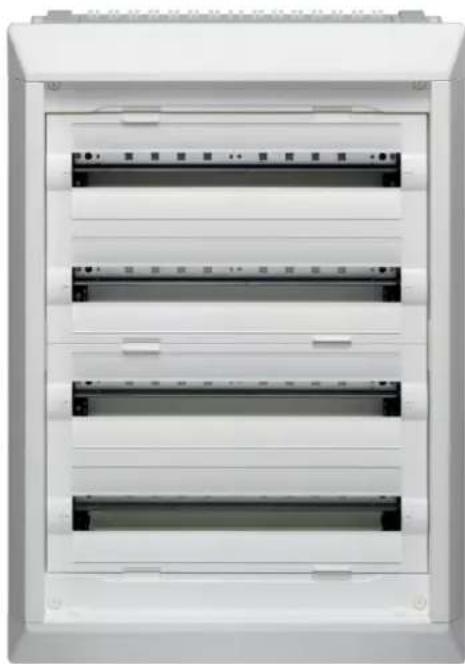
4.2.7 LN Version
- full equipped without door
- without Quick-Connect terminals
| Equipment standard | PEN QC holder 24 modules wide | Side cable bracket for flush | Instruction sheet w/o Quick-Connect explanation | Cover slot strip JP002 | 4 screws kit 4x16 for optional PEN holder or slid-er fixing | Plaster cardboard protection | Paper cover marking strips 24 mod. and holder |
| FU22LN | 1x | 4x | 1x | 1x | 1x | 1x | 2x |
| FU32LN | 1x | 6x | 1x | 1x | 1x | 1x | 3x |
| FU42LN | 1x | 8x | 1x | 1x | 1x | 1x | 4x |
| FU52LN | 1x | 10x | 1x | 1x | 1x | 1x | 5x |
| FU62LN | 2x | 12x | 1x | 1x | 1x | 1x | 6x |
| FU72LN | 2x | 14x | 1x | 1x | 1x | 1x | 7x |
natural_image
Front view of a white electrical enclosure with multiple horizontal panels and ventilation slots (no visible text or symbols)Example: FU42LN
4.2.8 MN Version
- partly-equipped without door
- two first rows to complete
- with Quick-Connect terminals Green/Yellow & Blue
- flush high-depth version
| Equipment standard | PEN QC holder 24 modules wide | Quick-Connect modules | Jumpers | Side cable bracket for flush | Instruction sheet with Quick-Connect explanation | Cover slot strip JP002 | 4 screws kit 4x16 for optional PEN holder or slider fixing | Plaster cardboard protection | Paper cover marking strips 24 mod. and holder |
| FU22MN | 1x | 1x KN10N / 1x KN10E | - | - | 1x | 1x | 1x | 1x | - |
| FU32MN | 1x | 1x KN18N / 1x KN18E | - | 2x | 1x | 1x | 1x | 1x | 1x |
| FU42MN | 1x | 1x KN22N / 1x KN22E | - | 4x | 1x | 1x | 1x | 1x | 2x |
| FU52MN | 1x | 1x KN26N / 1x KN26E | - | 6x | 1x | 1x | 1x | 1x | 3x |
| FU62MN | 2x | 2x KN18N / 2x KN18E | 1x KN99N / 1x KN99E | 8x | 1x | 1x | 1x | 1x | 4x |
| FU72MN | 2x | 2x KN18N / 2x KN18E | 1x KN99N / 1x KN99E | 10x | 1x | 1x | 1x | 1x | 5x |

natural_image
Exterior view of a white electrical cabinet with multiple horizontal slats and mounting brackets (no text or symbols visible)Example: FU72MN
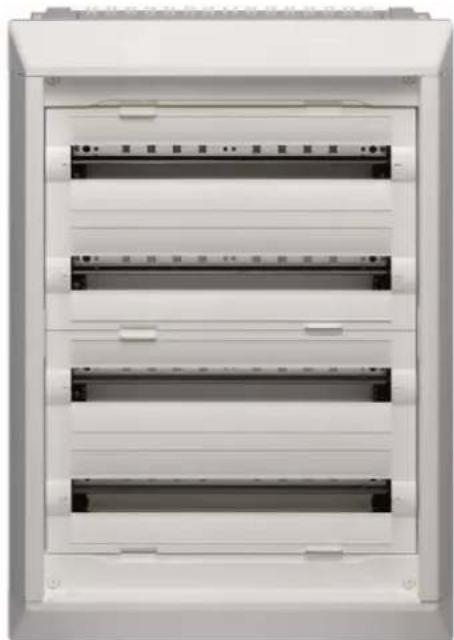
4.2.9 RN Version
- full-equipped without door
- with Quick-Connect terminals Green/Yellow & Blue
| Equipment standard | PEN QC holder 24 modules wide | Quick-Connect modules | Jumpers | Side cable bracket for flush | Instruction sheet with Quick-Connect explanation | Cover slot strip JP002 | 4 screws kit 4x16 for optional PEN holder or slider fixing | Plaster cardboard protection | Paper cover marking strips 24 mod. and holder |
| FU22RN | 1x | 1x KN10N / 1x KN10E | - | 4x | 1x | 1x | 1x | 1x | 2x |
| FU32RN | 1x | 1x KN18N / 1x KN18E | - | 6x | 1x | 1x | 1x | 1x | 3x |
| FU42RN | 1x | 1x KN22N / 1x KN22E | - | 8x | 1x | 1x | 1x | 1x | 4x |
| FU52RN | 1x | 1x KN26N / 1x KN26E | - | 10x | 1x | 1x | 1x | 1x | 5x |
| FU62RN | 2x | 2x KN18N / 2x KN18E | 1x KN99N / 1x KN99E | 12x | 1x | 1x | 1x | 1x | 6x |
| FU72RN | 2x | 2x KN18N / 2x KN18E | 1x KN99N / 1x KN99E | 14x | 1x | 1x | 1x | 1x | 7x |
natural_image
Front view of a white electrical cabinet with multiple horizontal panels and ventilation slots (no visible text or labels)Example: FU42RN
5 Doors for flush and surface enclosures
Chapter index
External dimensions 36
Door mounting into enclosure frames 38
Door hinges 39
5.1 External dimensions
natural_image
Simple white rectangular door with a side railing, no text or symbols visiblenatural_image
Technical diagram showing a rectangular frame with internal components and a side view of a vertical rod (no text or symbols)
natural_image
Blank rectangular panel with a gray center and white border, no visible text or symbolsnatural_image
Diagram showing a door with a handle and a side view of a vertical panel (no text or symbols)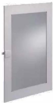
natural_image
Exterior view of a modern office building (no signage)- Standard closing system can be sealed with max ∅ 1,5 mm wire

natural_image
Close-up of a white plastic door with yellow wires and a green ball attached (no text or symbols visible)- Standard closing system is available as spare part with reference FD00S0
5.2 Door mounting into enclosure frames
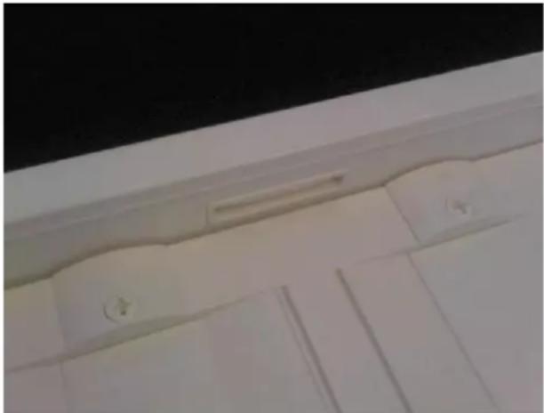
In New VegaD flush enclosures, customer doesn't have to punch out metal openings for door closing latch, as they are already punched.
natural_image
Close-up of a white wall corner with decorative trim and doorways (no visible text or symbols)Also in New VegaD surface enclosures, customer doesn't have to punch out plastic openings for door closing latch, as they are already extruded.

natural_image
Interior view of a white shower shower with a door and window (no visible text or symbols)5.3 Door hinges
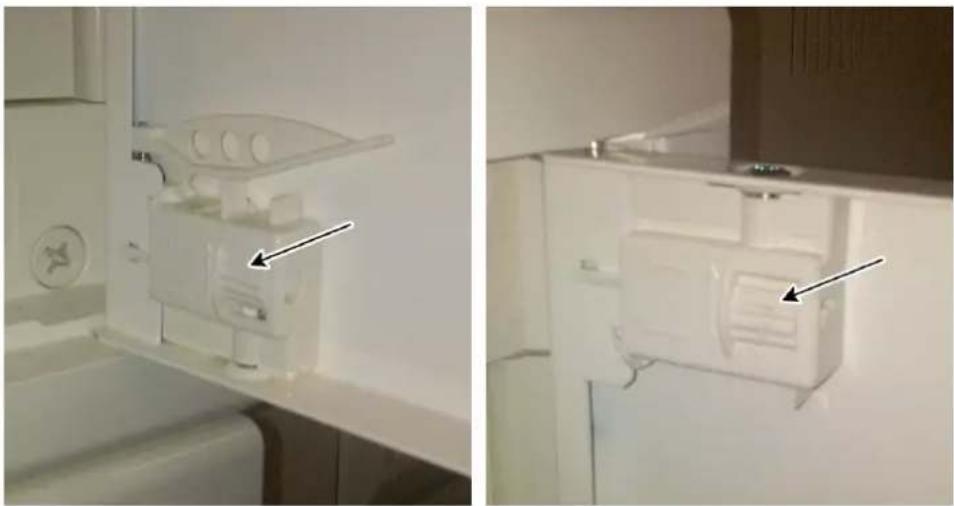
Each door is composed of 1 fix hinge and 1 removable one.
Both hinge positions can be adjusted up to 2mm by hand by turning small wheel (arrow), so that door fits perfectly into frame.
natural_image
Two views of a white plastic appliance mounted on a kitchen counter, with no visible text or symbols.
natural_image
Close-up of a white appliance front panel with a circular button and a black knob, showing no visible text or symbols.Hinges have a small gasket on metal pin, to prevent water to enter into enclosure and thus preserve IPx1.
6 Accessories
Chapter index
Naming rules 41
Equipment units 42
Single and spare parts 52
6.1 Naming rules
Equipment units, accessories and spare parts for New VegaD system have been named according these rules:
first 2 letters: always FD
first number: 0 for equipment units, accessories and spare parts (New VegaD system only)
second number: 0 for simple accessories and spare parts
1 for equipment units 1-row height 150 mm
2 for equipment units 2-rows height 300 mm
3 for equipment units 3-rows height 450 mm
third letter: Product type
third number: Product version
Examples
FD01A1:

FD01A2:

FD02K1:

6.2 Equipment units

- Equipment units are compatible with surface and flush high-depth versions.
- Equipment units are not compatible with flush low-depth versions.
6.2.1 FD01.. = Equipment units, height 150 mm
FD01A1: Kit for 1 distribution DIN rail (430 x 150 x 147 mm)
- with 1x label holder+paperstrip 24 modules, 4 mounting screws and 2 cable brackets for surface delivered-by
- with 150 mm slotted cover 24 modules.

natural_image
Exterior view of a white rectangular electronic device with black connectors and orange cable (no text or symbols visible)FD01A2: Kit for 1 depth-adjustable DIN rail (430 x 150 x 147 mm)
- with 4 mounting screws, 20 module DIN rail 370 mm long and 2 rail insulating parts delivered-by
- with 150 mm plain cover

natural_image
White plastic electrical enclosure with metal frame and three small components (no text or symbols visible)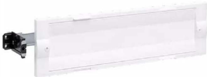
natural_image
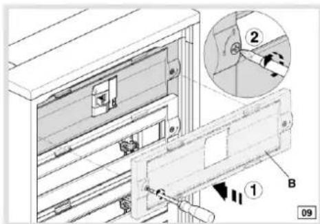
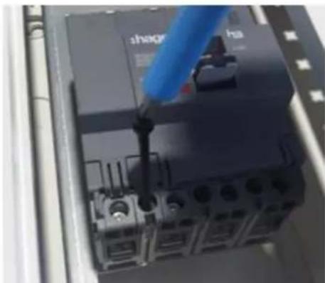
White rectangular electronic component with black connector and mounting bracket (no visible text or symbols)FD01K1: Kit for 160 A MCCB horizontal 3 and 4 poles (430 x 150 x 147 mm)
- with 1x label holder+paperstrip 24 mod., 1 blanking strip 1,5 module (27 mm) and 4 mounting screws delivered-by
- MCCB H3 or H3+ 3 or 4 poles 160 A to screw-in horizontally
- label holder & paperstrip 24 mod. to cut-out to wished size before snapping-in on cover slot
- USP: kit enables smallest MCCB mounting volume on the market
- with a second cover for mounting of MCCB H3+ P160
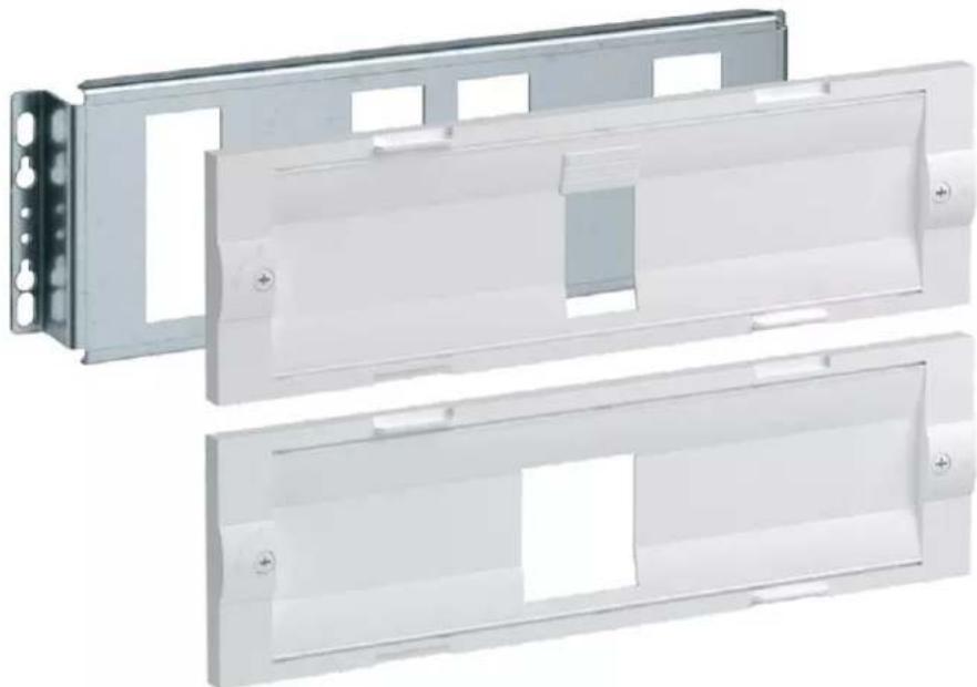
natural_image
Two white plastic electrical enclosure panels with mounting holes and mounting holes, shown from different angles (no text or symbols visible)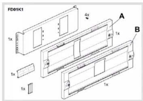
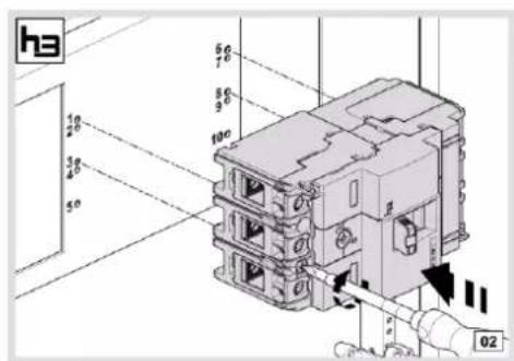
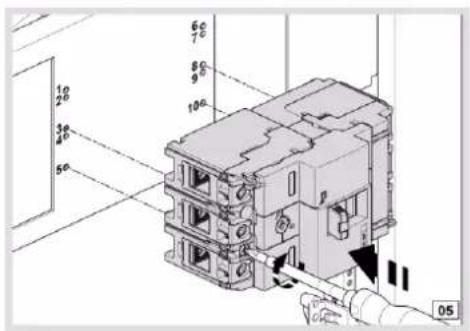


natural_image
Close-up of a blue-handled tool applying black plastic to a black electrical component (no visible text or symbols)
natural_image
Two black cylindrical pins or probes on a plain background (no text or symbols)MCCB fixing on metal plate with M4 screws delivered-by
6.2.2 FD02.. = Equipment units, height 300 mm
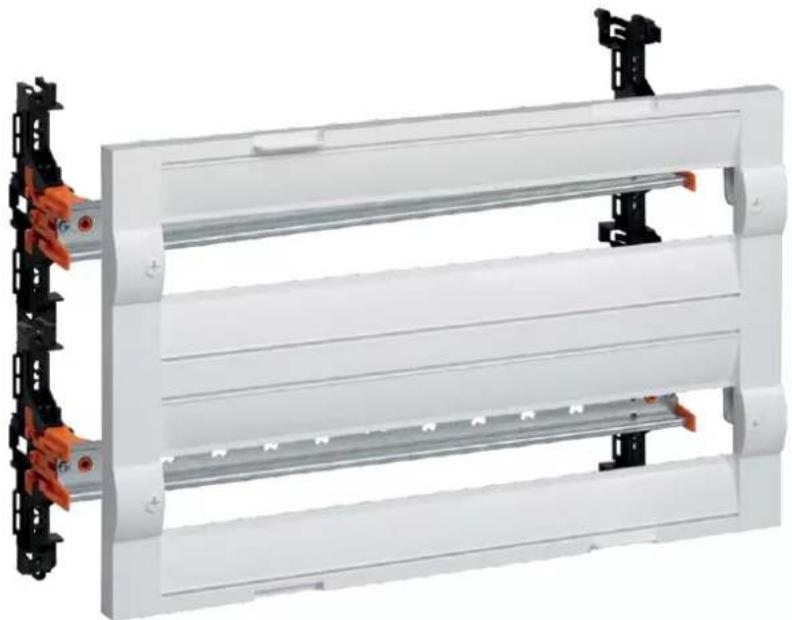
FD02A1: Kit with 2 distribution DIN rails (430 x 300 x 147 mm)
- with 2x label holder+paperstrip 24 mod., 4 mounting screws and 4 cable brackets surface delivered-by.
-
- with 300 mm 2x slotted cover 24 mod.
natural_image
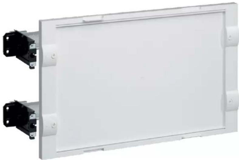
Exterior view of a white modular device with black connectors and orange connectors (no text or symbols visible)FD02A2: Kit with 2 depth-adjustable DIN rails (430 x 300 x 147 mm)
- with 8 mounting screws and 4 DIN rail insulating parts delivered-by
- with 300 mm plain cover
natural_image
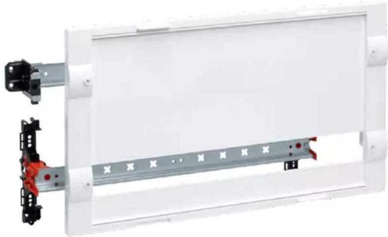
Exterior view of a white rectangular electronic device with two black connectors attached (no text or symbols visible)FD02A3: Kit with 1 depth-adjustable DIN rail and 1 standard DIN rail (430 x 300 x 147 mm)
- with 1x label holder+paperstrip 24 mod., 2 cable brackets surface, 8 mounting screws and 2 DIN rail insulating parts delivered-by
- with 300 mm 1x slotted cover 24 mod.
natural_image
Exterior view of a white rectangular electronic panel with metal contacts and red connectors (no text or symbols visible)FD02C2: Kit with depth-adjustable perforated plate (430 x 300 x 147 mm)
- with 4 DIN rail insulating parts and 12 mounting screws delivered-by
- with ∅ 3,2 perforated plate (370 x 290 x 1,2 mm)

natural_image
Exterior view of a white rectangular panel with black connectors and perforated side panels (no text or symbols)FD02F1: Kit with french DB plate (for Disjoncteur de Branchement) (430 x 300 x 147 mm)
- with 2x label holder+paperstrip 7 mod. premounted, 4 premounted screws delivered-by
- with removable 7 mod. DIN rail insulation parts
- with 250 x 250 x 40 mm French Gamma platine premounted

natural_image
Exterior view of a white plastic electrical enclosure with internal components (no text or symbols visible)FD02F2: Kit with french DB + linky meter plate (430 x 300 x 147 mm)
- with 2x label holder+paperstrip 7 mod. and 4 premounted screws delivered-by
- with removable 7 mod. DIN rail insulation parts
- with 250 x 225 x 45 mm French Gamma platine premounted

natural_image
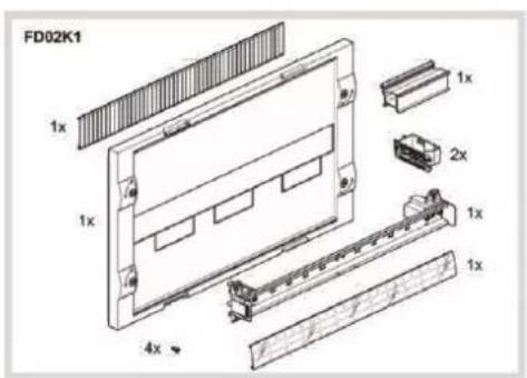
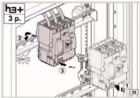
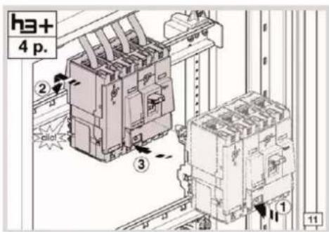
Exterior view of a white plastic electrical enclosure with internal components (no text or symbols visible)FD02K1: Kit for 160 A MCCB vertical 3 and 4 poles (430 x 300 x 147 mm)
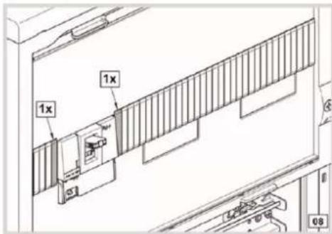
- with 1x label holder+paperstrip 24 mod., 1 plastic elevation part for modular devices, 1 blanking strip 12 mod., 2 cable brackets surface and 4 mounting screws delivered-by
- MCCB H3 3 or 4 poles 160 A to snap-in on DIN rail (MCCB not included)
- Kit also compatible with MCCB H3+ P160 3 or 4 poles

natural_image
Exterior view of a white rectangular electronic enclosure with a black metal panel and mounting bracket (no text or symbols visible)
natural_image
Two black plastic mechanical clamps with threaded ends and mounting brackets (no text or symbols visible)NB: Cable brackets for FD...N can be also mounted-in on kit in flush high depth enclosure





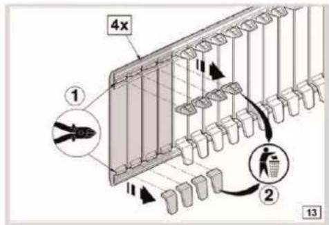

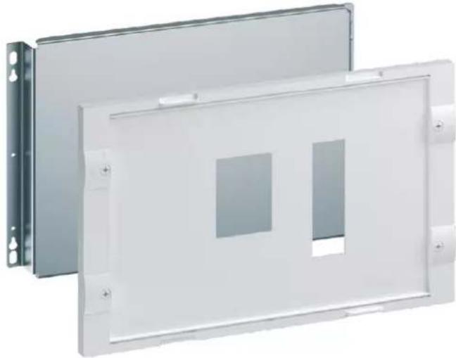
FD02K2: Kit for 250A MCCB (In 160 A) vertical 3 and 4 poles (430 x 300 x 147 mm)
- with 1x label holder+paperstrip 7 mod. delivered-by
- MCCB H3+ P160 3 or 4 poles 250 A with add-on bloc to screw-in horizontally
natural_image
Two white rectangular metal panels with square cutouts, mounted on a wall (no text or symbols visible)FD02V2: Kit for motorized change over switch 160 A (430 x 300 x 147 mm)
- with 1x label holder+paperstrip 24 mod., 1 blanking strip 24 mod., 1 positioning aid metallic bar and 4 mounting screws delivered-by
- Kit can be mounted in New VegaD surface FDxxxN and flush high-depth FUxxAN -GN -MN enclosures for mounting modular switches HIC4..A until 160 A.

natural_image
Exterior view of a white rectangular electronic device with a metal bracket and mounting holes (no text or symbols visible)6.2.3 FD03.. = Equipment units, height 450 mm
FD03A1: Kit with 3 distribution DIN rails (430 x 450 x 147 mm)
- with 3x label holder+paperstrip 24 mod., 12 mounting screws and 6 cable brackets surface delivered-by
- with 3x 150 mm slotted cover 24 mod.

natural_image
Exterior view of a multi-level industrial shelving unit with metal racks and red clamps (no text or symbols visible)FD03Z1: Kit for meter + main switch three-phase (430 x 450 x 147 mm)
- with French platine kit Tarif bleu triphasé fixed on mounting plate, special cover, 1x label holder+paperstrip (Univers) and 4 pre-mounted screws
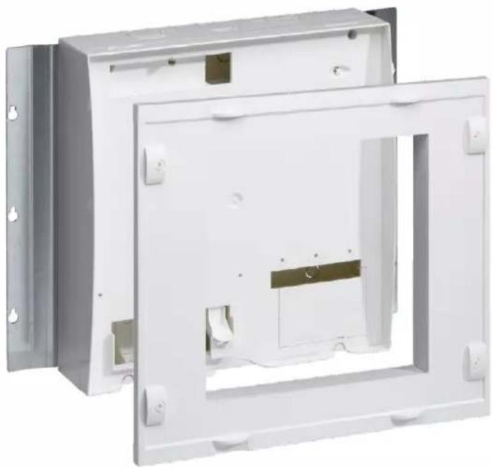
natural_image
Exterior view of a white electrical enclosure with mounting holes and internal compartments (no text or symbols visible)6.3 Single and spare parts
6.3.1 FD00A... = Standard Accessories
FD00A1: 10x label holder+paperstrip 24 mod.
- all 24 mod. slotted covers in enclosures and equipment kits are already delivered with 1x label holder+paperstrip 24 mod. to snap-in
- Reference to use as spare part or to double labels on a row (top and bottom, for example for Tebis with 2 outputs)
- paper length 428 mm
- 1-sided printed, other side blank

natural_image
Three rectangular panels with grid patterns, one light blue and one pink, displayed against a white background (no text or symbols)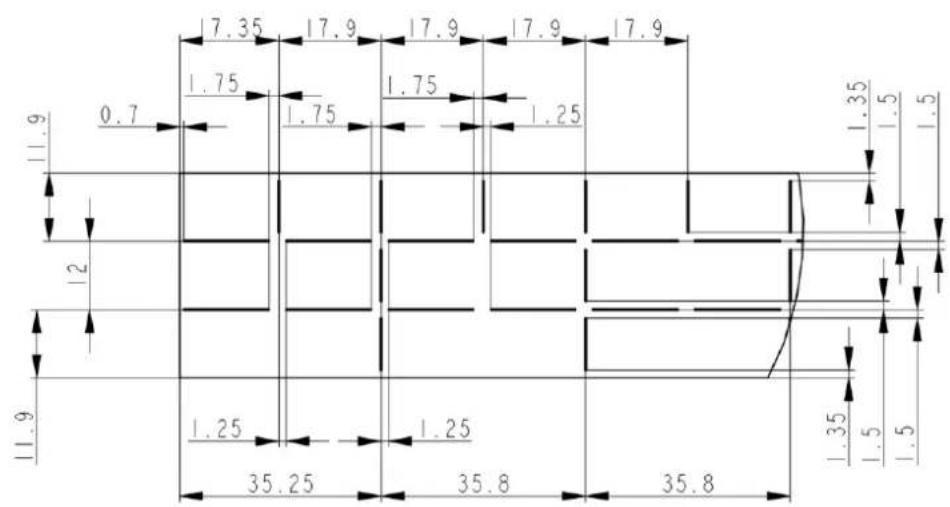
FD00A3: horizontal partition plate (surface only) 24 mod.
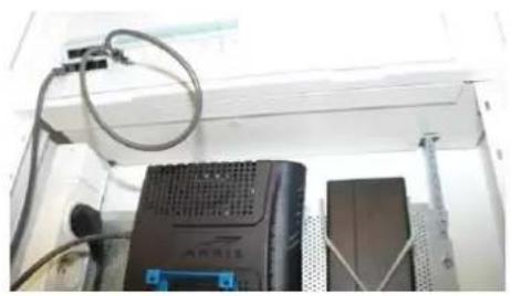
natural_image
Interior view of a server rack with network equipment and cables (no visible text or symbols)
natural_image
Exterior view of a white plastic panel or bracket with mounting flanges (no text or symbols visible)FD00A4: horizontal partition plate (flush high-depth only) 24 mod.

natural_image
Interior view of a printer or printer unit with visible circuitry and control knobs (no readable text or symbols)
natural_image
White plastic mechanical component with mounting holes and a flat top (no visible text or symbols)FD00A5: horizontal partition plate (flush low-depth only) 24 mod.
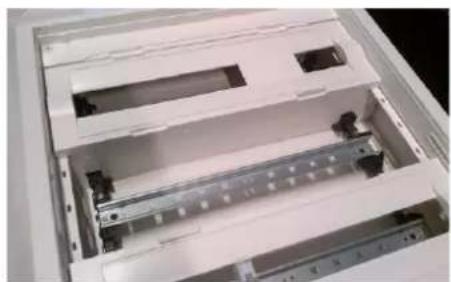
natural_image
Interior view of a white electronic device casing with internal compartments and connectors (no visible text or symbols)
natural_image
Exterior view of a white rectangular metal bracket with mounting flanges (no text or symbols)Partition IP2X to mount in 3 different positions:
Pos. 1: direct on uprights (no cut-out, direct use)
Pos. 2: between field with uprights and field modular (1 side to cut out)
Pos. 3: between 2 modular fields (2 sides to cut out)
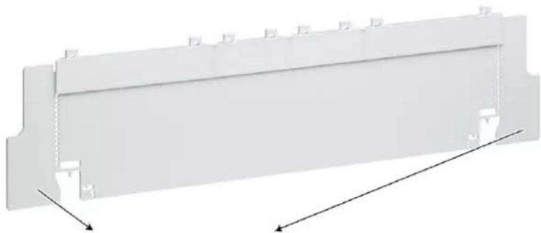
natural_image
White plastic panel with mounting holes and directional arrows indicating movement (no text or symbols)In all positions, it is possible to cut out side areas for vertical trunking access (surface only) or vertical cabling sideways.
See mounting instruction below:
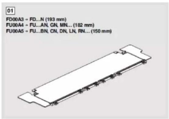


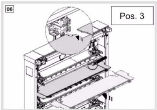
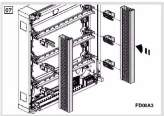
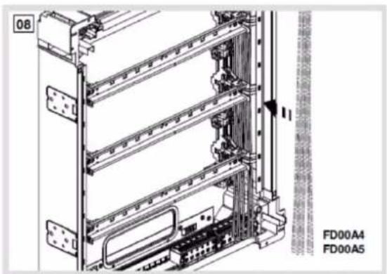

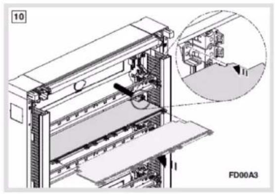
natural_image
Technical diagram of a server rack with an inset showing internal components (no text or symbols)

6.3.2 FD00B... = Side Brackets for vertical cables
FD00B1: 10x side Brackets for vertical cables for surface versions
- all equipped surface enclosures and kits with 24 mod. DIN rails are already delivered with 2 brackets per DIN rail
- Reference to use as spare part or to complete first two-rows in AN or MN versions or to equip GN versions

natural_image
Black plastic mechanical bracket with threaded end and mounting base (no text or symbols visible)USP: Part can be used in 3 different positions through cut-outs at 2 different points (see arrows):

natural_image
Close-up of a black plastic mechanical bracket with red arrows pointing to features (no text or symbols visible)Pos. 1: from top (without cut-out)
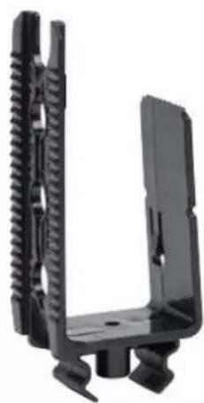
natural_image
Black plastic mechanical bracket with threaded end and mounting base (no text or symbols visible)Pos. 2: from top (with cut-out) for trunking fixation

natural_image
Close-up of a black mechanical clamp or bracket component (no visible text or symbols)Pos. 3: turned 180° (with or without cut-out)
Pos. 1:

natural_image
Technical diagram of a mechanical assembly with no visible text or symbols

natural_image
Hand operating a mechanical assembly with a tool, no visible text or symbolsPart can be snapped-in into 3 different depths (20 mm raster) and loosen though finger pressure under orange DIN rail holder.
Pos. 2:

natural_image
Technical diagram of a server rack with cooling unit and internal components (no text or labels)Part can be snapped-in into 3 different depths (20 mm raster) and loosen though finger pressure under orange DIN rail holder. Tehalit trunkings BA7A / HA7 can be snapped on part cutted-out like this. Through 20 mm raster, height of vertical trunking cover can be adapted to horizontal trunking cover height (as Tehalit trunkings are 60, 80 or 100 mm high).
Pos. 3:
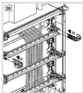
natural_image
Technical line drawing of a mechanical assembly with vertical components and mounting brackets (no text or symbols)
Part can be snapped-in into 3 different depths (20 mm raster) and loosen though finger pressure under orange DIN rail holder. Cover 30 mm width from Tehalit trunking BA7A / HA7 can be snapped on part mounted in this 180° turned position. Through 20 mm raster, height of vertical cover can be adapted to horizontal trunking cover height (as Tehalit trunkings are 60, 80 or 100 mm high).

natural_image
Interior view of a mechanical assembly with orange and black components, no visible text or symbols
natural_image
Diagram of a vertical panel structure with grid pattern, no text or symbols present
FD00B2: 10x side Brackets for vertical cables for flush versions
- all flush enclosures are already delivered with 2 brackets per DIN rail
- Reference to use as spare part or to complete first two-rows in AN or MN versions or to equip GN versions

natural_image
Illustration of a hand operating a mechanical device with a black arrow indicating direction (no text or symbols present)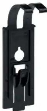
natural_image
Black plastic mechanical bracket with a central hole and two side slots (no text or symbols)- Part can be snapped-in into 1 single position and loosen:
- through pressure from top with screwdriver on plastic lever (flush low depth)
- through finger pressure under orange DIN rail holder (flush high depth)

6.3.3 FD00C... = Covers
Covers can be mounted on all surface and flush enclosures
FD00C1: 300 mm 2x slotted cover 24 mod.
- with 2x label holder+paperstrip 24 mod. delivered-by

natural_image
White rectangular metal frame with three horizontal slats, no text or symbols visibleFD00C2: 300 mm plain cover 24 mod.
- Plain area in the middle: 430 x 268 mm
- 2 slots top/bottom enable fixing of marking strips FD00A1

natural_image
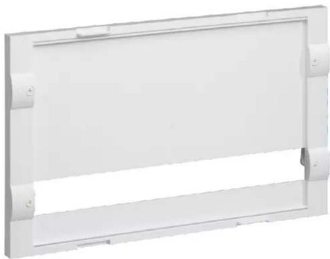
Exterior view of a white rectangular panel with rounded corners and mounting holes (no text or symbols)FD00C3: 300 mm 1x slotted cover 24 mod.
- with 1x label holder+paperstrip 24 mod. delivered-by
- 2 slots top/bottom enable fixing of marking strips FD00A1
natural_image
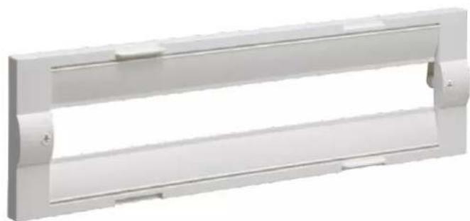
White rectangular frame with rounded corners and a central horizontal cutout (no text or symbols)FD00C4: 150 mm 1x slotted cover 24 mod.
- with 1x label holder+paperstrip 24 mod. delivered-by
- 2 slots top/bottom enable fixing of marking strips FD00A1
natural_image
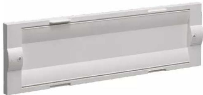
Exterior view of a white rectangular metal enclosure with recessed corners and mounting holes (no text or symbols)FD00C5: 150 mm plain cover 24 mod.
- 2 slots top/bottom enable fixing of marking strips FD00A1
natural_image
Exterior view of a white rectangular electronic device with two side slots and a central horizontal bar (no text or symbols)6.3.4 FD00M... = Mounting plates
Mounting plates can be screwed on all surface and flush enclosures, directly on vertical uprights.
FD00M1: 215 mm ∅ 3,2 perforated plate (434 x 215 x 1,2 mm)
- with 2x10 screws kit for multimedia (10x13 mm & 10x22 mm deep) and 6 mounting screws delivered-by
- 2 plates can be mounted on top of each other within a 3-row empty area (450 mm height) with 10 mm spacing for cable through-out in between

- Plate compatible with device holder VZ02MM and fixing strips VZ340 (not included)

natural_image
Exterior view of a perforated metal panel with mounting holes and three small screws at the bottom (no text or symbols)FD00M2: 290 mm plain plate (434 x 290 x 2 mm)
- with 6 mounting screws delivered-by
- plates can be mounted on top of each other (1 each 2 rows empty area) (300 mm height) with 10 mm spacing for cable through-out in between

natural_image
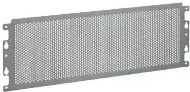
Exterior view of a gray rectangular panel with mounting holes and small pins (no text or symbols visible)FD00M3: 140 mm ∅ 3,2 perforated plate (434 x 140 x 1,2 mm)
- with 2x5 screws kit for multimedia (5x13 mm & 5x22 mm deep) and 4 mounting screws delivered-by
- plates can be mounted on top of each other (1 each 1 row empty area) (150 mm height) with 10 mm spacing for cable through-out in between
- Plate compatible with device holder VZ02MM and fixing strips VZ340 (not included)
natural_image
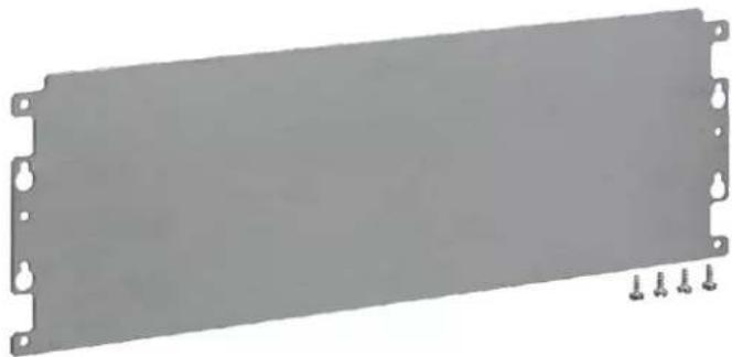
Metal perforated panel with mounting holes and a grid pattern (no text or symbols)FD00M4: 140 mm plain plate (434 x 140 x 2 mm)
- with 4 mounting screws delivered-by
- plates can be mounted on top of each other (1 each 1 row empty area) (150 mm height) with 10 mm spacing for cable through-out in between
natural_image
Exterior view of a gray rectangular panel with mounting holes and three small screws at the bottom (no text or symbols)6.3.5 FD00G... = Gallery Adapter for VegaD surface versions (FD...)
FD00E1 (Adapter for Systo range) has been replaced by FD00G1 (Adapter for Gallery range), as Systo range has been phased out.
FD00G1: Adapter for Gallery range

natural_image
Exterior view of a square metal frame with mounting holes (no text or symbols)Gallery compatibility
FD00G1 is compatible with following wiring accessories (non-exhaustive list):
| 16 A socket outletFrench 16 A | 16 A socket outletSchuko16 A | Cable entry | Blanking plug | Warning lightred/green | ||
 |  |  | 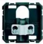 |  |  |  |
| WXF100 | WXD100B | WXF160B | WXF155 | WXD155B^[1] | 2 x WXF688B | WXF601 |
| Other types available:WXF102 (other cover),WXF105 (other cover) | Other types available:WXA699,WXD101B,WXD103B,WXD104R | Other LED colours and types available: WXF602, WXF603 | ||||
| 2 x WXF687B | WXF689B | |||||
[1] not compatible with WS179 and 91... covers
| RJ45 | HDMI | USB | Optical Fiber | ||||
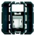 |  |  |  |  |  |  | |
| WXF226 | WXD202B | WXF632 | WXD744T | WXF644 | WXD202B | WXF645 | WXD202B |
 |  |  |  |  |  | ||
| 2 x WXF226 | 2 x WXD201B | 2 x WXF644 | 2 x WXD201B | ||||
| Other grades and types available: WXF202, WXF221, WXF222, WXF223, WXF224, WXF225, WXF226, WXF228, WXF230, WXF231, WXF232, WXF233 (...). Other covers available: WXD205B, WXF206B, WXF230B ... | 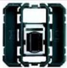 |  | |||||
| WXF642 | WXD202B | ||||||
Other grades and types available: WXF202, WXF221, WXF222, WXF223, WXF224, WXF225, WXF226, WXF228, WXF230, WXF231, WXF232, WXF233 (...). Other covers available: WXD205B, WXF206B, WXF230B ...
| Switches(with push-button function) | Switch with key | Other switches | ||
 |  |  |  |  |
| WXF003 | WXD000B^[1] | WXF615B | WXF010 | WXD000B^[1] |
 |  |  |  | |
| 2 x WXF003 | 2 x WXD010B [1] | 2 x WXF010 | 2 x WXD010B [1] | |
 |  | |||
| WXF008 | WXD004B^[1]WXD013B^[1] | |||
 |  | |||
| WXF005^[1]WXF024^[1] | WXD005B^[1] | |||
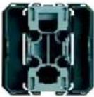 |  | |||
| WXF023 | WXD001B^[1] | |||
 | 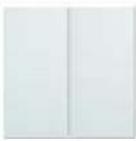 | |||
| 2 x WXF023 | 2 x WXD011B [1] | |||
[1] not compatible with WS179 and 91... covers
Note: In this overview table, the last reference letter B stands for pure white.
Other colours are also available:
D Oyster white, T Titane, N Black, E Orange, R Red, V Green.

All Gallery products 47 mm wide are not all compatible with Gallery adapter. Compatibility check on demand.

natural_image
Close-up of a yellow and red electrical switch component with a white plastic housing (no text or symbols visible)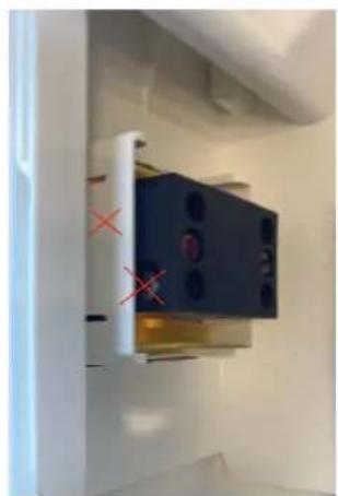
natural_image
Interior view of a room with a black appliance mounted on a wall, marked with red Xs (no visible text or symbols)Example: push buttons WXF610 and 611 are not compatible with FD00G1 because the wiring interferes with the plastic walls of the adapter.
Protection cover compatibility
FD00G1 is also compatible with IP41 protection cover WS179 and other 91... refs from Berker, that can be snapped-in:
Protective cover

Other colours and types available:
918282501, 918282505, 918282507, 918282509,
918282510, 918282524, 918282578 and 919882502,
919882505, 919882506
WS179
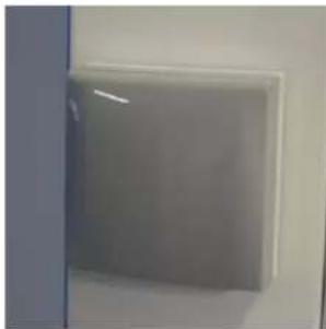
natural_image
Close-up of a white square vent or vent on a wall, no text or symbols visible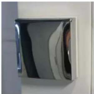
natural_image
Close-up of a metallic wall-mounted device with reflective surfaces (no text or symbols visible)
natural_image
White wall-mounted electronic device mounted on a wall, no visible text or symbols
natural_image
White plastic mechanical component with a semicircular cutout and mounting holes (no text or symbols visible)Hager ref WS179 in RAL 9010 mounted on FD00G1
IP41 cover for Berker socket to snap on VegaD socket adapter (available in 10 colours)
| Standard cover | Colour | Berker reference | Hager reference |  |  |
| polar white glossy | 918282509 | WS179 | |||
| black glossy | 918282510 | ||||
| stainless steel coated satin | 918282524 | 918282501 (brown) | |||
| brown matt | 918282501 | ||||
| anthracite matt | 918282505 | ||||
| grey glossy | 918282507 | ||||
| chrome-plated matt | 918282578 | ||||
| Cover with la-bel stripe | Colour | Berker reference |  |  | |
| polar white glossy | 919882502 | ||||
| anthracite matt | 919882505 | ||||
| grey glossy | 919882506 | 919882502 (white) |
919882502 (white)
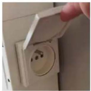
natural_image
Hand installing a white electrical socket on a wall (no text or symbols visible)
natural_image
White wall-mounted electronic device mounted on a vertical panel, no visible text or symbols
natural_image
Close-up of a white wall-mounted electrical outlet mounted on a wall, with black cables visible (no text or symbols)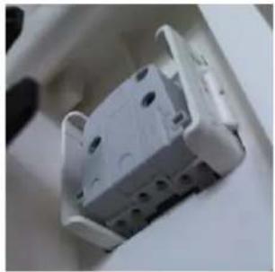
natural_image
Close-up of a white plastic electrical outlet socket with mounting holes (no visible text or symbols)WXF100/WXD100B+WS179

natural_image
Close-up of a hand holding a white plastic device with a circular dial and handle (no visible text or symbols)WXF615B+WS179

natural_image
Exterior view of a wall-mounted cabinet or shelf unit mounted on a door (no visible text or symbols)WXF100/WXD100B+9 1828 25 07

natural_image
Close-up of a hand inserting a plastic into an open electrical socket (no text or symbols visible)
natural_image
Close-up of a metallic door with a curved glass panel on the left side (no visible text or symbols)WXF100/WXD100B + 9 1828 25 78

All Gallery products 47mm wide are not all compatible with IP41 cover (see note [1] in tables on page 63 and following).

natural_image
Two white plastic electronic devices: one open and one with a curved top panel (no text or symbols visible)Example of non-compatibility: cable entry set WXF155+WXD155B is too big for WS179 and other 91... covers from Berker
Mounting instruction

natural_image
3D technical illustration of a mechanical housing assembly with two views: front view and side view (no text or symbols)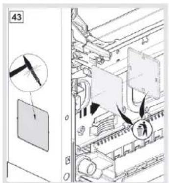
- Perforate side opening side with hammer [43]


- Stick gasket on adapter [44]
- Snap adapter into enclosure with top inscription on top [45]
- Snap socket outlet with wires into adapter [46]
Socket mounting:
| Step | Action |
| 1 | Put gasket on adapter |
| 2 | Release protection foil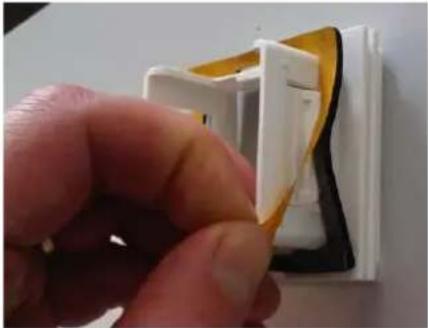 |
| 3 | Take care of top side for socket adaptations and snap adapter into enclosure 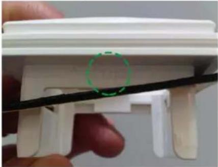 |
| 4 | Fix wires to socket  |
| 5 | Pass wires into side opening 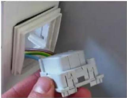 |
| 6 | Clip socket into adapter 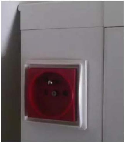 |
→ See mounting instruction
Socket dismounting:
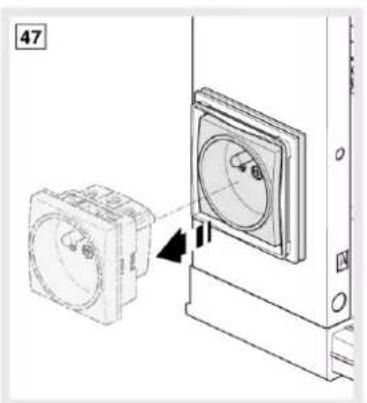
| Step | Action | |
| 1 | Unscrew socket front cover | |
 | ||
| 2 | 4 x unsnap with small flat screwdriver socket snaps (from outside or inside) and push socket out of enclosure | |
 |  | |
| 3 | 2 x unsnap adapter snaps with heavy finger pressure top/bottom or left/right hand side | |
 |  | |
→See mounting instruction
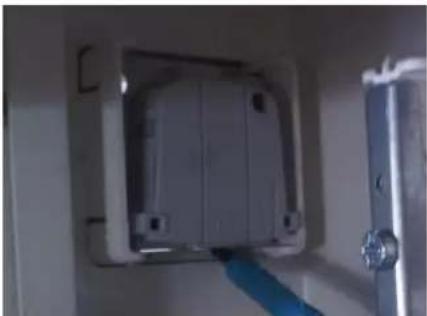
To dismount a socket outlet, it is necessary to unscrew front plate and unsnap back plate with small flat screwdriver while pushing out back plate from the inside with the second hand.
natural_image
Technical line drawing showing a device mounted on a wall-mounted unit with a magnified inset view (no text or symbols)
natural_image
Technical diagram showing a mechanical assembly with a pin inserted into a housing, no text or symbols present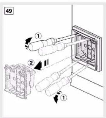
6.3.6 FD00F... = Fixation kit
FD00F1: Fixation kit (for surface versions only)
- to associate 2 surface enclosures vertically
- to associate 2 surface enclosures horizontally
- to associate 2 surface enclosures vertically
- to associate 2 surface enclosures horizontally
natural_image
Product assembly diagram showing wall-mounted components and screw fasteners (no text or symbols)Vertical association (first enclosure already wall-mounted)
Needed are following parts:

natural_image
Pure electrical circuit lines without any symbols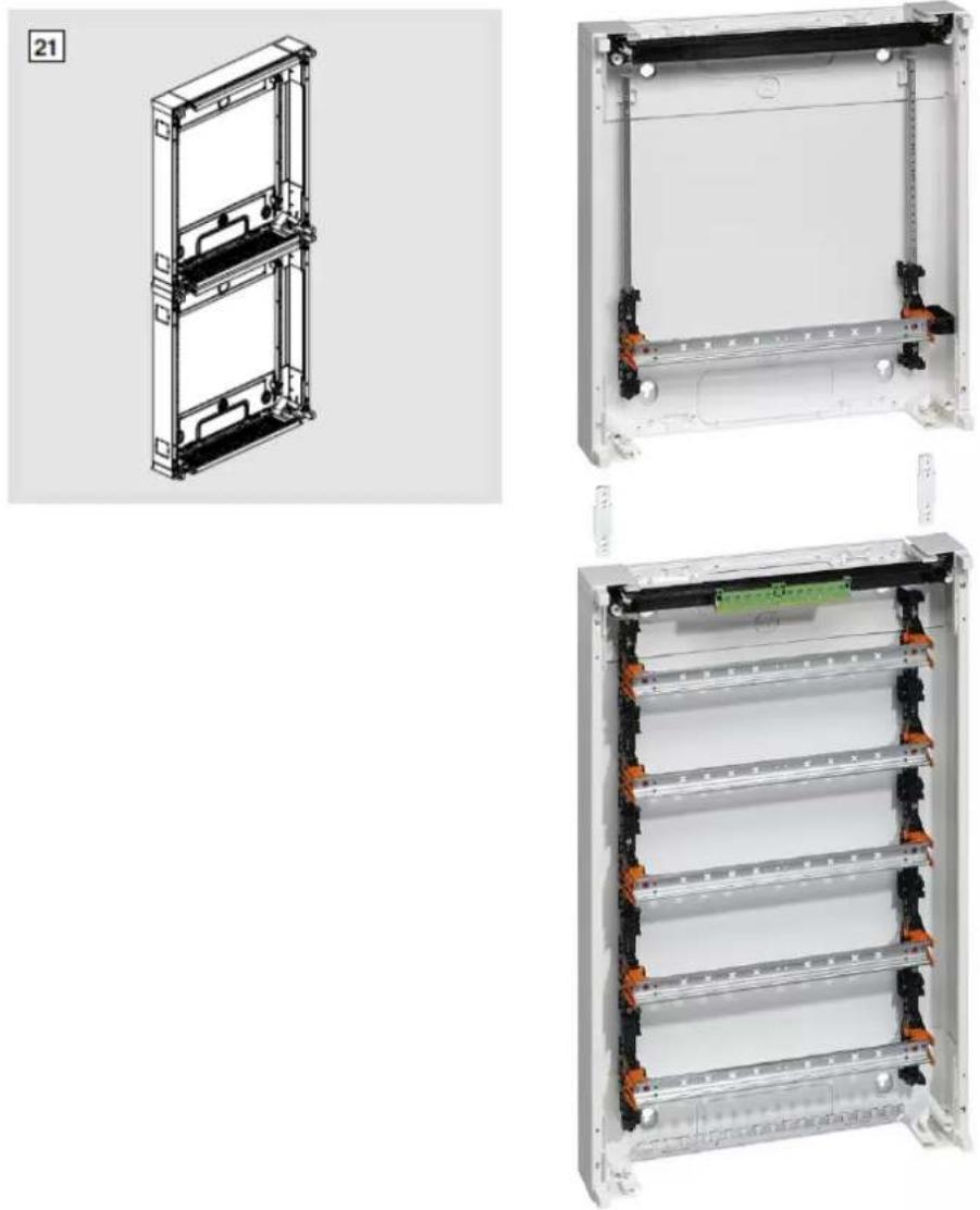
Step
Action
1
Perforate holes left/right hand side with screwdriver and hammer [22]

| Step | Action |
| 2 | Insert fixing plates from the top and screw them from the inside with M6 screws [23] |
 | |
| 3 | Cut cable entry plate opening as wished and stick gasket in between [24] [25] [26] |
 | |
 | |
 | |
| 4 | Insert top enclosure through fixing plates above first enclosure [27] |
 | |
| 5 | Screw them from the inside with M6 screws [27] |
| 6 | Put insulation caps above all M6 screw heads [27] |
Horizontal association (first enclosure already wall-mounted)
Needed are following parts:

natural_image
Collection of white and black plastic components including square cutouts, circular recessed panels, rectangular brackets, and screws (no text or symbols visible)
natural_image
Technical line drawing of a dual-panel electronic device with mounting brackets and control panels (no text or symbols)
natural_image
Two white electrical panel units with black connectors and orange connectors, mounted on metal racks (no visible text or symbols)Step Action
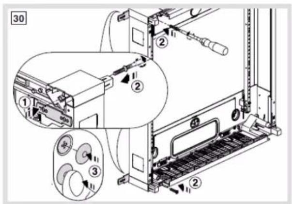
1 Perforate holes top/bottom side with screwdriver and hammer [29]

2 Insert fixing plates from the side and screw them from the inside with M6 screws [30]
Step
Action
3
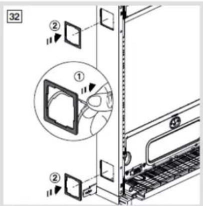
Perforate side openings with a hammer and stick gasket around them [31] [32]

4
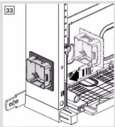
Insert side plates top/bottom from the inside [33]
natural_image
Technical line drawing of an electrical enclosure with wiring and a door, no visible text or symbols5
Snap second enclosure from the side over fixing plates [34]
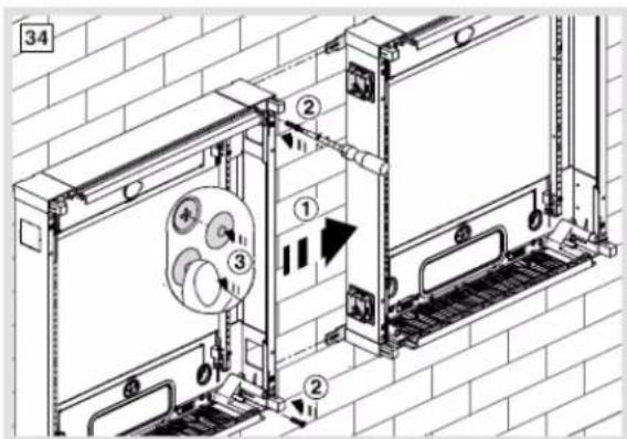
6
Screw them from the inside with M6 screws [34]
7
Put insulation caps above all M6 screw heads [34]
8
Fix second enclosure at the wall with both hands free (USP)
Horizontal association or vertical association with both enclosures on table
⇒ Same process as related above plus following step:

- Reinforce stability of assembly by 4x screwing top/bottom plastic parts of the enclosure with metallic back panel with 4 small screws delivered-by
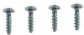
FD00F2: Fixation kit (for surface versions only)
- to mount a surface enclosure with 4 external fixing plates

natural_image
Five metal bracket components with holes and six screws, arranged in a row (no text or symbols visible)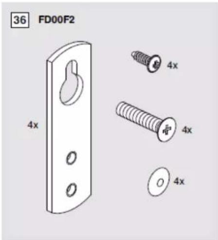
Step Action
1 Perforate holes left/hand right side and top/bottom with screwdriver and hammer [37]
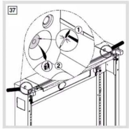
Step
Action
2
Insert external fixing plates from the top and screw them from the inside with M6 screws [38]

3
Reinforce stability of assembly by 4x screwing top/bottom plastic parts of the enclosure with metallic back panel with 4 small screws delivered-by [39]
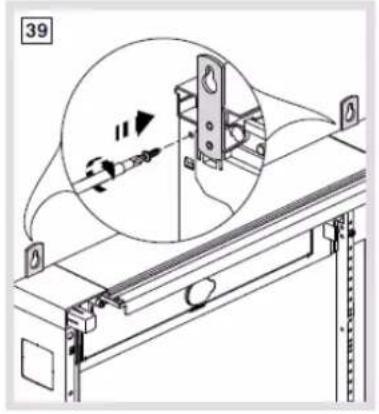
natural_image
Technical line drawing of a mechanical assembly with an inset showing a magnified view of a component (no text or symbols present)
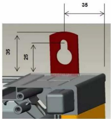
Distances between fixing holes: Width = 480 mm / Height = Enclosure height + 50 mm
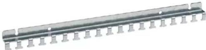
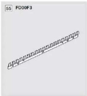
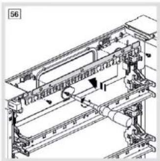
FD00F3: Bar for cables fixation (for surface and flush versions)
- to fix incoming / outgoing cables with cable straps
natural_image
Metal mechanical component with evenly spaced pins and mounting holes (no text or symbols visible)⇒ Part delivered-by in each AN and DN surface version.

natural_image
Technical line drawing of a mechanical assembly with no visible text or symbols
natural_image
Technical line drawing of a mechanical clamp or bracket assembly mounted on a vertical rod (no text or symbols)
natural_image
Front view of a white electronic device chassis with black connectors and mounting holes (no visible text or symbols)Bar can also be fixed on the wall above cable entry

natural_image
Close-up of a mechanical assembly with vertical black rods and mounting holes (no visible text or symbols)
Up to 9,5 mm width for big cable tie fixing
Quick dismounting sideways
6.3.7 FD00H... = DIN rail Holders for equipment units
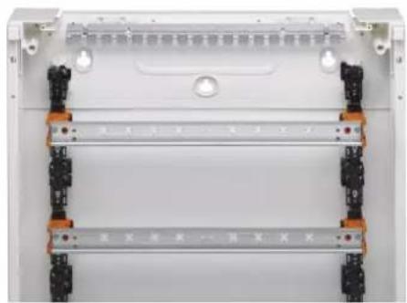
FD00H1: 2x Base element for DIN rail fixation (for surface, flush high-depth and flush low-depth versions)
- to use as spare part or to complete first two-rows in AN or MN versions or to equip GN versions
- part to snap-in on vertical upright and 1x to screw-in each 150 mm
- with 6 standard mounting screws delivered-by (2 for DIN rail fixation)
- kit to complete with FD00H2 and UZ02B9

natural_image
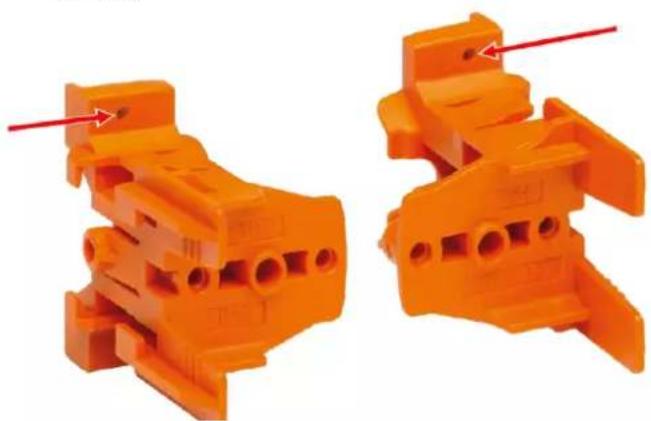
Two black plastic mechanical components with structural details, shown from different angles (no text or symbols visible)FD00H2: 2x Top element for DIN rail fixation (for surface and flush high-depth versions)
- to use as spare part or to complete first two-rows in AN or MN versions or to equip GN versions
- part to slide-in on base element FD00H1
- not compatible with flush low-depth versions
- with 4 standard mounting screws delivered-by for DIN rail fixation
- for more stability or big devices, the part can be screwed to the base element at 2 places (see arrow below) with the 13 mm long screws (4x delivered-by in this kit)
natural_image
Two orange plastic electrical connectors with red arrows pointing to features (no text or symbols visible)6.3.8 FD00Q... = Quick-Connect & terminal holder
FD00Q1: 1x Quick-Connect holder (for surface, flush high-depth and flush low-depth versions)
- to use as spare part or to complete 22, 32, 42 or 52 versions (delivery form with only 1)
- Part to snap-in on back panel top/bottom plastic part
- Part can be optionally 2x screwed to back panel top/bottom plastic part with 4 screw bag delivered-by
- Fixation screws are the same than for P1, P2 and P3 cable entry plate fixing (∅ 4x16 mm).
- max. input: 80 x 4 mm ^2 / 24 x 25 mm ^2


natural_image
Black rectangular mechanical component with side brackets and mounting feet (no visible text or symbols)Earth Terminal Blocks
| Description | Width | Reference | |
 | Terminal, QC, PE, 6 connections | 30 mm | KN06E |
 | Terminal, QC, PE, 10 connections | 45 mm | KN10E |
 | Terminal, QC, PE, 14 connections | 60 mm | KN14E |
 | Terminal, QC, PE, 18 connections | 75 mm | KN18E |
 | Terminal, QC, PE, 22 connections | 90 mm | KN22E |
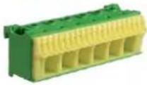 | Terminal, QC, PE, 26 connections | 105 mm | KN26E |
Jumper for Earth Terminal Blocks

To connect the Earth Terminal Blocks KNxxE
| Description | Reference |
| Terminals, QC, PE, Jumper | KN99E |
Other terminal blocks and jumpers available for neutral and phase like KNxxN, KNxxP...
6.3.9 FD00P... = Plate for cable entry
FD00P1: 1x Plate for cable entry (Slider) with rectangular openings (for surface, flush high-depth and flush low-depth versions)
- Slider included top/bottom in each surface and flush version
- Reference to use as spare part
- For better stability, the plate can be 2x screwed to back panel top/bottom plastic part with 4 screw bag (∅ 4x16 mm) delivered-by

natural_image
Three views of a gray industrial enclosure or enclosure with grid patterns, shown from different angles (no text or symbols visible)Maximum rectangular area for cable entry: 420 x 80 mm

FD00P2: 1x Plate for cable entry (Slider) with 2 water-proof flanges IP41 (for surface, flush high-depth and flush low-depth versions)
- Slider with 2 water-proof flanges IP41 to mount-in
- Reference to use for water-proof direct cable throughout
- The water-proof flanges can be ordered as single parts under VZ741
- For better stability, the plate can be 2x screwed to back panel top/bottom plastic part with 4 screw bag (∅ 4x16 mm) delivered-by

natural_image
Exterior view of a dual-chamber electronic component with multiple pin slots (no text or symbols visible)FD00P3: 1x Plate for cable entry (Slider) with tube openings (for surface, flush high-depth and flush low-depth versions)
- Slider with pre-perforated rounded openings for tubes
- For better stability, the plate can be 2x screwed to back panel top/bottom plastic part with 4 screw bag (∅ 4x16 mm) delivered-by

natural_image
Exterior view of a rectangular electronic component with two internal channels (no text or symbols)![svagor 4x Ø12 mm[1] 5x Ø12/20 mm[1] 4x Ø12/16/25 mm[1]](/content/2026/06/1178416/images/f00528effbdb357aa357bc8fb8a5c6d04776f79beecfc0b2f58a7f9d93af0511.jpg)
[1] per half
FD00P4: 2x Plate for cable entry (Side plate) (for surface versions only)
- USP: M40 cable gland head can be screwed directly into side plate winding (without its screwing ring)
- M25 cable gland can also be mounted-in (with its screwing ring)

natural_image
Two identical white square panels with concentric circular recessed patterns, no text or symbols visible.
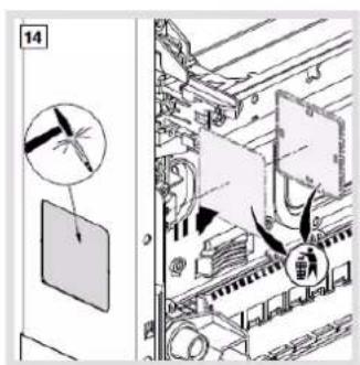


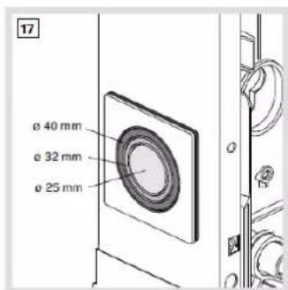


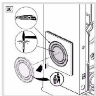

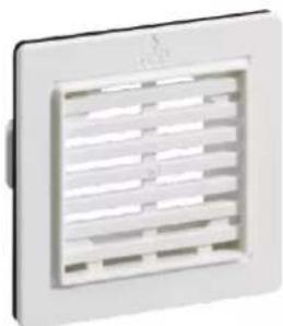
FD00P5: 2x Side plate for aeration (for surface versions only)

Aeration grid reduces IP41 to IP30. For mounting see page 85.
natural_image
White square vent with horizontal slats, no text or symbols visible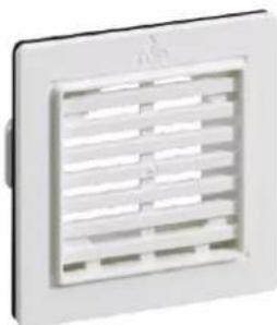
natural_image
White air vent grater with horizontal slats (no text or symbols visible)
natural_image
Close-up of a white wall-mounted air conditioner unit with a ventilation grille (no visible text or symbols)Power loss effect +27 % to 64 % with kit mounted asymmetrically (for example top left- and bottom right-hand side) on distribution enclosure FD (see also chapter 'power loss' starting on page 123).
| Enclosure | Permissible power loss P_perm for standard surface enclosures without ventilation openings | Permissible power loss P_perm for standard surface enclosures with diagonal ventilation openings FD00P5 | ||||||||||||||
| Type | HeightHmm | WidthBmm | DepthBmm | Surface mounted with temperature rise Δt | % Enclosure height | Δ% | Surface mounted with temperature rise Δt | % Enclosure height | ||||||||
| 10KW | 15KW | 20KW | 25KW | 30KW | 10KW | 15KW | 20KW | 25KW | 30KW | |||||||
| FD22... | 450 | 500 | 193 (Depth installation room 135 mm) | 15 | 24,8 | 35,4 | 46,8 | 58,7 | 75 | +27 % | 15 | 24,8 | 35,4 | 46,8 | 58,7 | 75 |
| 17,9 | 29,7 | 42,4 | 56 | 70,2 | 50 | +23 % | 17,9 | 29,7 | 42,4 | 56 | 70,2 | 50 | ||||
| FD32... | 600 | 17,7 | 29,4 | 42 | 55,4 | 69,5 | 75 | +28 % | 17,7 | 29,4 | 42 | 55,4 | 69,5 | 75 | ||
| 22,2 | 36,8 | 52,7 | 69,5 | 87,2 | 50 | +24 % | 22,2 | 36,8 | 52,7 | 69,5 | 87,2 | 50 | ||||
| FD42... | 750 | 20,6 | 34,1 | 48,8 | 64,4 | 80,7 | 75 | +29 % | 20,6 | 34,1 | 48,8 | 64,4 | 80,7 | 75 | ||
| 26,5 | 43,8 | 62,7 | 82,7 | 130,8 | 50 | +25 % | 26,5 | 43,8 | 62,7 | 82,7 | 103,8 | 50 | ||||
| FD52... | 900 | 23,5 | 38,9 | 55,6 | 73,4 | 92,1 | 75 | +40 % | 23,5 | 38,9 | 55,6 | 73,4 | 92,1 | 75 | ||
| 30,6 | 50,7 | 72,6 | 95,8 | 120,1 | 50 | +30 % | 30,6 | 50,7 | 72,6 | 95,8 | 120,1 | 50 | ||||
| FD62... | 1050 | 26,4 | 43,7 | 62,5 | 82,5 | 103,5 | 75 | +51 % | 26,4 | 43,7 | 62,5 | 82,5 | 103,5 | 75 | ||
| 34,7 | 57,5 | 82,3 | 108,6 | 136,5 | 50 | +40 % | 34,7 | 57,5 | 82,3 | 108,6 | 136,2 | 50 | ||||
| FD72... | 1200 | 28,5 | 47,1 | 67,4 | 89 | 111,6 | 75 | +64 % | 28,5 | 47,1 | 67,4 | 89 | 111,6 | 75 | ||
| 39,3 | 65 | 93 | 122,7 | 154 | 50 | +50 % | 39,3 | 65 | 93 | 122,7 | 154 | 50 | ||||
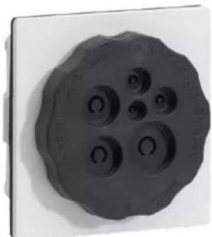
FD00P6: Side plate for cable entry with M40 flange (for surface versions only)
- Composed of a plastic adapter with gasket and of a water- and dust-proof round black flange M40 screwed-in. For mounting see page 85.
-
Round flange with 6 openings for following cable diameters:
-
1 × 2,0 - 4,0 mm
- 2 x 3,0 - 6,0 mm
- 2 × 5,0 - 9,0 mm
-
1 x 7,5 - 12,0 mm
-
USP: Openings can be reclosed with finger touch and contain a cable strain relief functionality
- For mounting see page 85.
natural_image
Close-up of a dark, irregularly shaped object with four circular indentations on a white background (no text or symbols visible)FD00P6

natural_image
Exterior view of a white cabinet with a black electrical outlet cable inserted, no visible text or symbols
natural_image
Close-up of a white electrical outlet socket connected to a black plastic plug, with blue vertical lines indicating connection points (no text or symbols visible)FD00P6 mounting into New VegaD surface board
VZ741: New VegaD cable entry flange IP41
- The flange can be snapped-in on back panel of surface and flush enclosures after cut-out of plastic wall
- All enclosure back panels can receive 2 flanges for cable back entry (top and bottom)
- Reference is also part of slider FD00P2
- This flange is also mounted in Vector boxes VE...

natural_image
White plastic electronic component with multiple cylindrical pins and mounting brackets (no visible text or symbols)VZ741

natural_image
Close-up of an electronic device with a green connector and black connectors, showing internal components and wiring (no visible text or symbols)Example: Cable entry flange VZ741 mounted on the back of a New VegaD flush enclosure
6.3.10 FD00S... = Serrure (closing system)
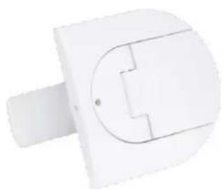
FD00S0: Standard closing system as spare part
natural_image
White electrical plug with a U-shaped socket and side port (no text or symbols visible)
flowchart
graph TD
    A["Air Inlet"] --> B["Collection"]
    B --> C["Recycle"]
    C --> D["Discharge"]
    D --> E["Outlet"]
    style A fill:#f9f,stroke:#333
    style E fill:#bbf,stroke:#333
Mounting / Dismounting schema
FD00S1 / FD00S4: key closing system 1242E / 405

natural_image
Close-up of a metallic keychain with two keys, no text or symbols visible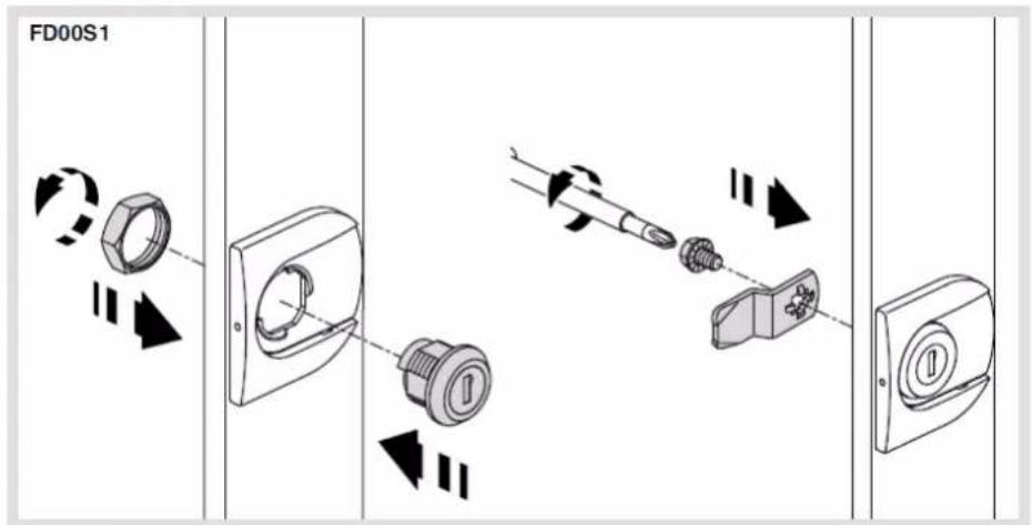
Mounting schema
FD00S2 / FD00S3 / FD00S5: special closing system triangle 7 mm / square 7 mm / two-way 3 mm
- All references are delivered with tool

Mounting schema
6.3.11 FD00T... = Trunking
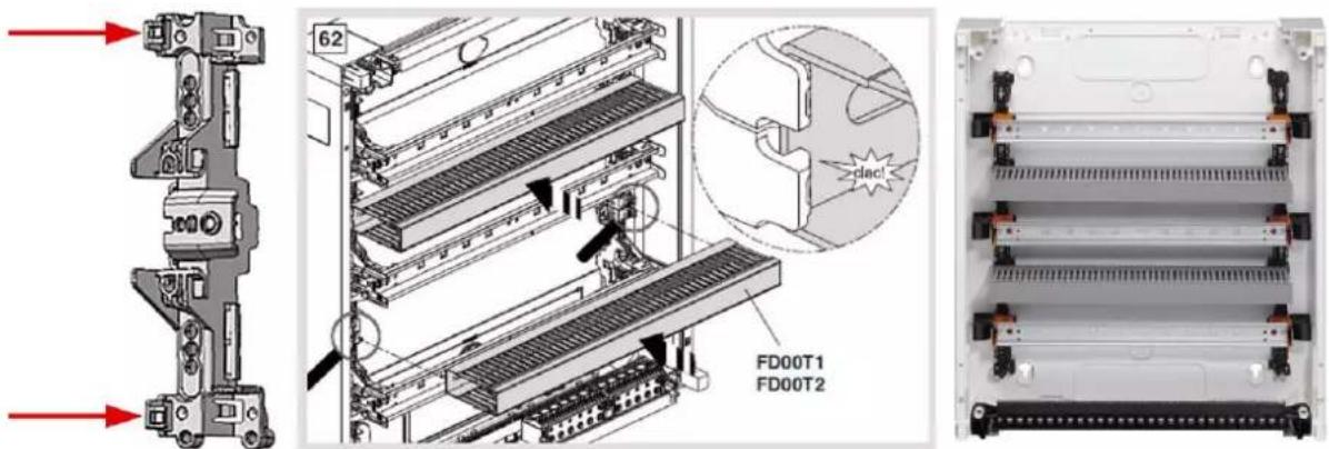
For having a nice parallel cable management from MCBs with 1 or 2 outgoings (18 mm or 9 mm distance between wires) to horizontal cable tray, a new cutting tool has been made for BA7A profiles.
The resulting cable trays have 9 mm distance between slots and are available under FD00T1 and FD00T2 product codes.

natural_image
Technical illustration of a microfluidic device with a 3D schematic and its corresponding cross-sectional view (no text or symbols)FD00T1: 4x horizontal cable tray kit 80x30 with 9 mm interslot distance in PVC
- dark grey colour RAL 7030
- 438 mm width for horizontal quick fixing between 2 rows without tool
- delivered with covers
- BA7A profile basis
- not compatible with flush low-depth, as 80 mm height would collide with cover

natural_image
Two metallic industrial heat exchangers shown from different angles (no text or symbols visible)Horizontal trunking can be quickly fixed between 2 rows without tool, simply by clipping it on black base element FD00H1 (see red arrows in graphic on next page).
FD00T2: horizontal trunking kit 80x30 with 9 mm interslot distance halogen-free
- soft grey colour RAL 7035
- 438 mm width
- delivered with covers
- HA7 profile basis
- not compatible with flush low-depth, as 80 mm height would collide with cover

natural_image
Close-up of a transparent plastic tray with metal grating and a small label (no visible text or symbols)Both horizontal trunkings can be quickly fixed between 2 rows without tool, simply by clipping them on black base element FD00H1 (see red arrows).
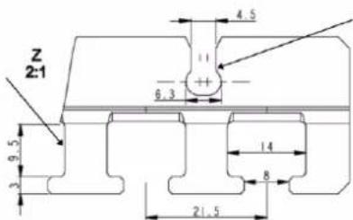
Standard BA7A profile with 12,5 mm interslot distance are also compatible with New VegaD fixing, but have to be cut from 2 m profile to 438 mm length by the installer.
Thus, it is also possible to clip-on smaller BA7A profiles cut to 438 mm like 40x30 or 60x30 in flush low-depth enclosures. See compatibility below:
| BA7A range (PCV)RAL 7030 dark grey | HA7 range (PC/ABS)RAL 7035 soft grey | ||||
| BA7A40030 | 40x30 mm | HA740030 | 40x30 mm | For all New VegaD surface and flush | |
| BA7A60030 | 60x30 mm | HA760030 | 60x30 mm | ||
| BA7A80030 | 80x30 mm | HA780030 | 80x30 mm |  | Only for New VegaD surface + flush high-depth |
| BA7A100030 | 100x30 mm | HA7100030 | 100x30 mm | ||
6.3.12 BA7A/HA7... = vertical trunkings sideways
BA7A and HA7 trunking references shown in table above are compatible with brackets FD00B1 (see page 56) and can be mounted vertically in New VegaD surface enclosures. Thus, it is possible to combine horizontal and vertical trunkings to get a clean installation picture.

natural_image
Interior view of a server rack unit with multiple parallel slots and black connectors (no visible text or labels)Horizontal and vertical trunking installation into surface enclosure
6.3.13 FZ... = Univers cable storage and hiding box
In order to hide incoming cables over a New VegaD surface enclosure like FD52..., customer can "puzzle" a wooden-based bulky storing box or can order cable storing ducts FZ..., developed for the Univers range:

Homemade wooden box mounting


Univers cable storage box mounting
FZ142: width 550 mm, cross section 155 x 115 mm (RAL 9010)

natural_image
Exterior view of a modern office building (no signage)FZ142 550 mm wide (RAL 9010)

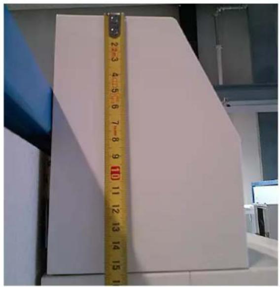
Cross section [mm] 115 x 155 or 155 x 115
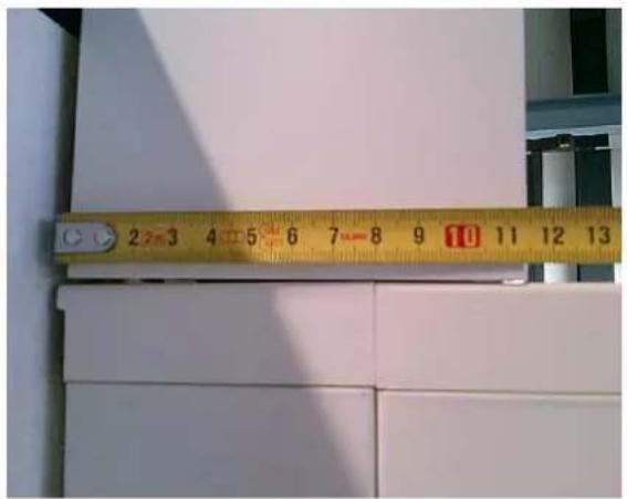
FZ442: width 550 mm, cross section 195 x 155 mm (RAL 9010)
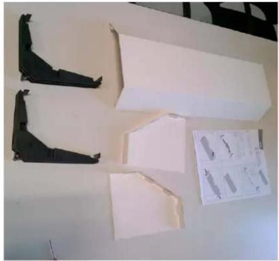
natural_image
Exterior view of a white plastic panel with black metal brackets and a small inset diagram showing internal components (no text or symbols)FZ442 550 mm wide (RAL 9010)

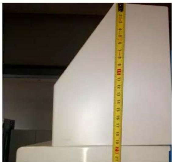
Cross section [mm] 155 x 195 or 195 x 155
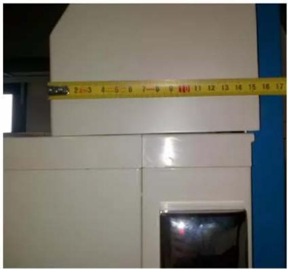
FZ352: width 550 mm, cross section 195 x 155 mm (RAL 7035)
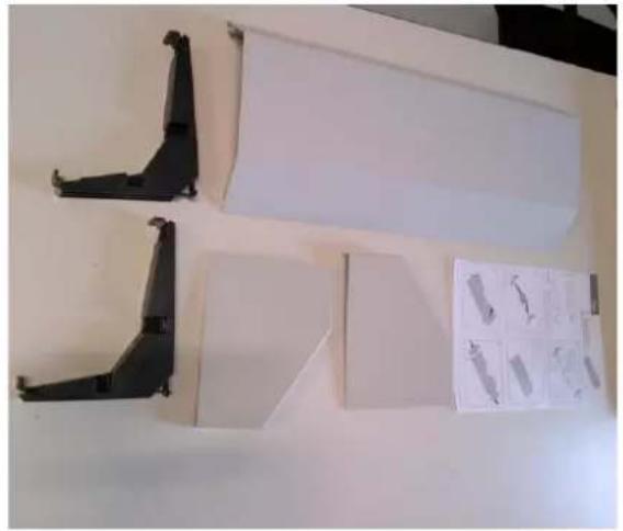
natural_image
Exterior view of a modern office building (no signage)FZ352 550 mm wide (RAL 7035)


Cross section
[mm]
155 x 195
or
195 x 155
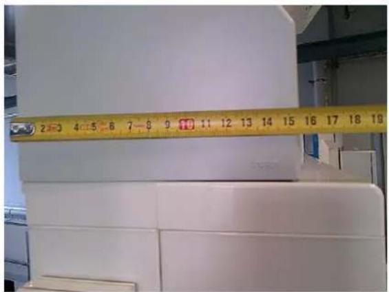
natural_image
Close-up of a white plastic sheet with a yellow measuring tape placed between them (no visible text or symbols)Mounting instructions:
| Step | Action | |
| 1 | Choose long side ... | ... or short side |
 |  | |
| 2 | Screw into wall | |
 | ||
| 3 | Clip in front cover | |
 | ||
| 4 | Clip in side covers | |
 | ||
Step
Action
5
Ready
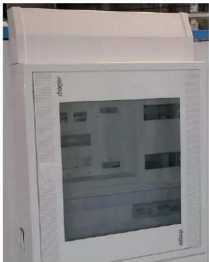
6
If needed, cut out opening for external vertical cable tray integration

natural_image
Technical illustration of a saw cutting through a rectangular block, with an inset showing the blade (no text or symbols)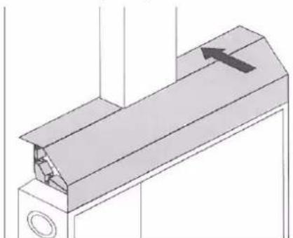
natural_image
Technical line drawing of a mechanical component with a highlighted section and arrow indicator (no text or symbols)
natural_image
Exterior view of a white industrial machine with 'hager' branding on the side panel (no other text or symbols visible)Mounting examples:
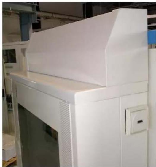
natural_image
Exterior view of a white industrial machine in a factory setting (no visible text or symbols)FZ142 mounted 155 mm vertically
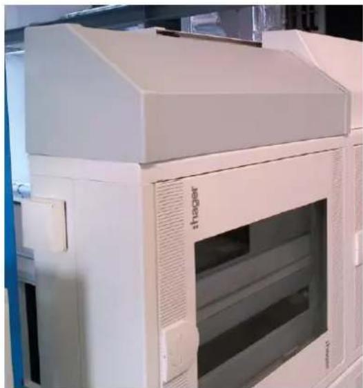
natural_image
Exterior view of a white industrial machine with open vent and control panel (no visible text or symbols)FZ352 mounted 155 mm vertically

natural_image
Exterior view of a white industrial machine with visible branding and control panel (no readable text or symbols)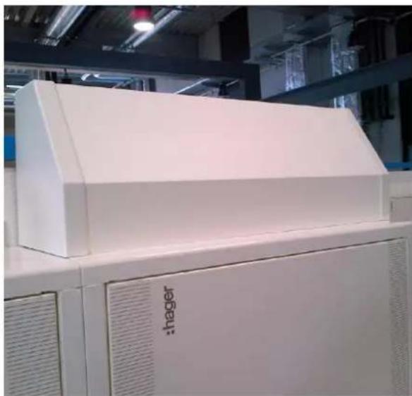
natural_image
Exterior view of a white industrial machine labeled 'hager' in a factory setting (no other text or symbols visible)FZ442 mounted 195 mm vertically

natural_image
Exterior view of a white industrial equipment cabinet with open doors and internal compartments (no visible text or symbols)FZ352+ FZ442 mounted 195 mm vertically
6.3.14 UZ...V. = Univers N cable brackets
UZ01V1: 20x adapter for cable bracket Univers N
natural_image
Black plastic mechanical bracket component (no text or symbols visible)- The adapter can be mounted on standard Univers DIN rail in each hole with flower shape
- The adapter can receive small bracket UZ25V2 (surface, flush high-depth and flush low-depth versions) or big bracket UZ25V1 (surface and flush high-depth versions only)
UZ25V1: 20x big bracket for cables Univers N
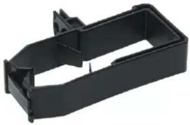
natural_image
Black plastic mechanical bracket component (no text or symbols visible)- Part to snap-in on adapter UZ01V1
- Single cover UT50C from cable tray Univers can be snapped on its top to hide cables below
UZ25V2: 20x small bracket for cables Univers N

natural_image
Black plastic mechanical component with cutouts and mounting holes (no text or symbols visible)- Part to snap-in on adapter UZ01V1
- Single cover UT50C from cable tray Univers can be snapped on its top to hide cables below
- Part can be also mounted 180° without adapter under standard Univers DIN rail in each hole with flower shape (surface and flush high-depth versions only)
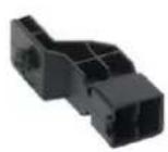
UZ01V1

UZ25V1

UZ25V2
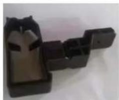
natural_image
Black plastic mechanical component with a central slot and two side slots (no text or symbols visible)UZ25V1 with UZ01V1

natural_image
Industrial machine with blue cables and mechanical components (no visible text or symbols)Mounting example in flush high-depth
6.3.15 Door frames as spare parts
Door frames for FD...N as spare part
| Enclosure height | FD Series (193 mm deep) | Reference ending letters | 1 | 2 | 3 | 4 |
| Top/bottom plastic part (2x needed) | Metallic side part RAL 9010 (2x needed) | Extruded plastic side part for cover fixation (2x needed) | Plastic screw kit (4 screws 1FD02900 included) | |||
| 450 | 22 | AN, BN, CN, DN, GN, LN, MN | 1FD02701 | 1FD05290 | 5D020100 | ZZ42BS |
| 600 | 32 | 1FD05390 | 5D020200 | |||
| 750 | 42 | AN, BN, CN, DN, GN, LN, MN, BMN | 1FD05890 | 5D020300 | ||
| 900 | 52 | 1FD05990 | 5D020400 | |||
| 1050 | 62 | AN, BN, CN, DN, GN, LN, MN | 1FD10390 | 5D020500 | ||
| 1200 | 72 | 1FD05790 | 5D020600 |

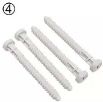
natural_image
Four metallic screw fasteners arranged in a row, no text or symbols visibleZZ42BS: Door frame fixing plastic screws as spare part

natural_image
Four metallic screw fasteners with threaded end caps, shown against a white background (no text or symbols visible)Door frame fixing plastic screws (for surface and flush) can be ordered as spare part under ZZ42BS ref (BS stands for "Blind frame Screws")
ZZ42BS
Door frames for FU...N as spare part
| Enclosure height | FU Series with high frame (72 mm overhead) | Reference ending letters | 1 | 2 | 3 | 4 |
| Top/bottom plastic part (2x needed) | Metallic side part RAL 9010 (2x needed) | Side part for door latch admission (2x needed) | Plastic screw kit (4 screws 1FD02900 included) | |||
| 537 | 22 | AN, GN, MN | 1FU07301 | 1FU06190 | 1FU06700 | ZZ42BS |
| 687 | 32 | 1FU06290 | ||||
| 837 | 42 | 1FU06390 | ||||
| 987 | 52 | 1FU06490 | ||||
| 1137 | 62 | 1FU06590 | ||||
| 1287 | 72 | 1FU06690 |
| Enclosure height | FU Series with flat frame (40 mm overhead) | Reference ending letters | 1 | 2 | 3 | 4 |
| Top/bottom plastic part (2x needed) | Metallic side part RAL 9010 (2x needed) | Side part for door latch admission (2x needed) | Plastic screw kit (4 screws 1FD02900 included) | |||
| 537 | 22 | BN, CN, DN, LN, RN | 1FU07201 | 1FU05190 | 1FU06700 | ZZ42BS |
| 687 | 32 | 1FU05290 | ||||
| 837 | 42 | 1FU05390 | ||||
| 987 | 52 | 1FU05490 | ||||
| 1137 | 62 | 1FU05590 | ||||
| 1287 | 72 | 1FU05690 |


natural_image
Four metallic screw fasteners arranged in a row, no text or symbols visible6.3.16 Vertical uprights and fixation accessories
Vertical uprights as spare part
To get vertical uprights as spare parts, kit UN0.FN ① + 4 screws ② have to be ordered.
| Enclosure height | FD or FU size | Reference ending letters | 1 | 2 |
| Vertical upright kit (2 uprights included) | Screw 4,8x25 (4x needed) | |||
| 450 / 537 | 22 | AN, BN, CN, DN, GN, LN, MN, RN | UN02FN | 5E460400 |
| 600 / 687 | 32 | AN, BN, CN, DN, GN, LN, MN, RN | UN03FN | |
| 750 / 837 | 42 | AN, BN, CN, DN, GN, LN, MN, RN, BMN | UN04FN | |
| 900 / 987 | 52 | AN, BN, CN, DN, GN, LN, MN, RN, BMN | UN05FN | |
| 1050 / 1137 | 62 | AN, BN, CN, DN, GN, LN, MN, RN | UN06FN | |
| 1200 / 1287 | 72 | AN, BN, CN, DN, GN, LN, MN, RN | UN07FN |
FU...N
FD...N
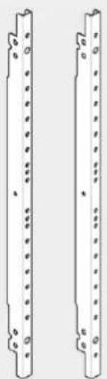
natural_image
Two identical mechanical components with evenly spaced holes, shown side by side (no text or symbols)
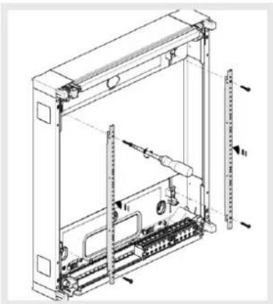
natural_image
Technical line drawing of an electrical enclosure with internal components and mounting brackets (no text or symbols)ZZ41SF: Lock nuts for vertical upright fixing as spare part
Lock nuts are required on each corner of the internal equipment system for screwing the vertical uprights to the enclosure body. They are premounted in every New VegaD enclosure.
Kit ZZ41SF (composed of 4 counterparts 5G000200) can be ordered separately, if for any reason one is missing.

natural_image
Four black plastic electrical connectors with mounting brackets (no text or symbols visible)ZZ41SF
In ZZ41SF, SF stands for "Screw Fixation".
7 Packaging and dimensions of enclosures
Chapter index
Pictures of packaging 107
Packaging use at the workshop or at the construction site 108
Labels 109
Dimensions and weights of enclosures 110
7.1 Pictures of packaging
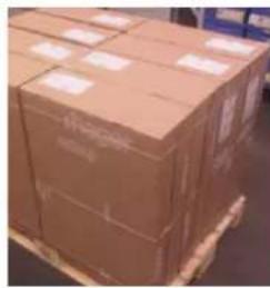
natural_image
Stacked cardboard boxes on a pallet in a warehouse (no visible text or labels)
Enclosures:
2-pieces Hager brand card-board packaging with 2 white Hager labels 175x90 mm
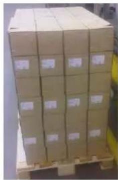
natural_image
Stacked cardboard boxes on a pallet (no visible text or labels)
Equipment units and covers: 1 piece Hager brand card-board packaging with 2 white Hager labels 85x60 mm
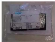
Single parts:
plastic bag packaging with 1 white Hager label 85x60 mm or pre-printed
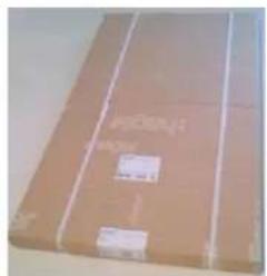
natural_image
Folded cardboard box with white shipping markings (no visible text or symbols)Single doors:
1-piece Hager brand card-board packaging with 2 white Hager labels 100x73 mm
7.2 Packaging use at the workshop or at the construction site
As both surface & flush protective cardboards are made of 2 pieces, New VegaD enclosure packagings are very easy to open. At the workshop or at the construction site, it is also recommended to use the first half for protecting frame or frame with door and the other half to for protecting back panel, chassis or door.
Surface enclosure packaging:

natural_image
Two cardboard boxes with internal components, one open and one closed, against a brick wall background (no visible text or symbols)Flush low- and high-depth enclosure packaging:

natural_image
Two cardboard boxes, one labeled 'hager' and the other empty, placed on a plain surface (no text or symbols on the boxes themselves)7.3 Labels
7.3.1 Labels on cardboard packaging
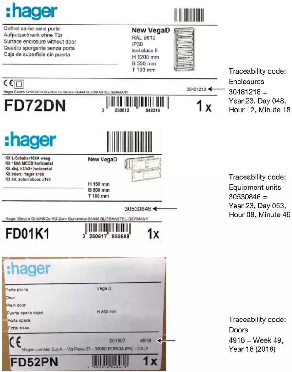
7.3.2 Enclosure type labels

7.4 Dimensions and weights of enclosures
7.4.1 Surface enclosures without door (FD...N)
| Surface enclosures New VegaD | Height | Width | Depth | N° per palette | Weight (unpacked) | Weight (packed) | Height (packed) | Width (packed) | Depth (packed) |
| mm | mm | mm | pcs. | kg | kg | mm | mm | mm | |
| FD22AN | 450 | 550 | 193 | 16 | 6,2 | 7,2 | 480 | 560 | 200 |
| FD22DN | 450 | 550 | 193 | 16 | 7,6 | 8,6 | 480 | 560 | 200 |
| FD22GN | 450 | 550 | 193 | 16 | 6 | 7 | 480 | 560 | 200 |
| FD22LN | 450 | 550 | 193 | 16 | 7,3 | 8,3 | 480 | 560 | 200 |
| FD22MN | 450 | 550 | 193 | 16 | 6,2 | 7,2 | 480 | 560 | 200 |
| FD22RN | 450 | 550 | 193 | 16 | 7,6 | 8,6 | 480 | 560 | 200 |
| FD32AN | 600 | 550 | 193 | 8 | 9 | 10 | 630 | 560 | 200 |
| FD32DN | 600 | 550 | 193 | 8 | 10 | 11,3 | 630 | 560 | 200 |
| FD32GN | 600 | 550 | 193 | 8 | 7,8 | 8,8 | 630 | 560 | 200 |
| FD32LN | 600 | 550 | 193 | 8 | 9,7 | 10,9 | 630 | 560 | 200 |
| FD32MN | 600 | 550 | 193 | 8 | 8,8 | 9,8 | 630 | 560 | 200 |
| FD32RN | 600 | 550 | 193 | 8 | 10 | 11,3 | 630 | 560 | 200 |
| FD32ZN | 600 | 550 | 193 | 8 | 11,9 | 13,2 | 630 | 560 | 200 |
| FD42AN | 750 | 550 | 193 | 8 | 10,6 | 11,8 | 780 | 560 | 200 |
| FD42DN | 750 | 550 | 193 | 8 | 12 | 13,2 | 780 | 560 | 200 |
| FD42GN | 750 | 550 | 193 | 8 | 9,2 | 10,3 | 780 | 560 | 200 |
| FD42LN | 750 | 550 | 193 | 8 | 11,6 | 12,8 | 780 | 560 | 200 |
| FD42MN | 750 | 550 | 193 | 8 | 10,4 | 11,6 | 780 | 560 | 200 |
| FD42RN | 750 | 550 | 193 | 8 | 12 | 13,2 | 780 | 560 | 200 |
| FD52AN | 900 | 550 | 193 | 8 | 12,6 | 14 | 930 | 560 | 200 |
| FD52DN | 900 | 550 | 193 | 8 | 14 | 15,4 | 930 | 560 | 200 |
| FD52GN | 900 | 550 | 193 | 8 | 10,8 | 12 | 930 | 560 | 200 |
| FD52LN | 900 | 550 | 193 | 8 | 13,7 | 15,1 | 930 | 560 | 200 |
| FD52MN | 900 | 550 | 193 | 8 | 12,6 | 14 | 930 | 560 | 200 |
| FD52RN | 900 | 550 | 193 | 8 | 14 | 15,4 | 930 | 560 | 200 |
| FD62AN | 1050 | 550 | 193 | 8 | 14,8 | 16,4 | 1080 | 560 | 200 |
| FD62DN | 1050 | 550 | 193 | 8 | 16,2 | 17,8 | 1080 | 560 | 200 |
| FD62GN | 1050 | 550 | 193 | 8 | 12,2 | 13,8 | 1080 | 560 | 200 |
| FD62LN | 1050 | 550 | 193 | 8 | 16 | 17,6 | 1080 | 560 | 200 |
| FD62MN | 1050 | 550 | 193 | 8 | 14,8 | 16,2 | 1080 | 560 | 200 |
| FD62RN | 1050 | 550 | 193 | 8 | 16,2 | 17,8 | 1080 | 560 | 200 |
| FD72AN | 1200 | 550 | 193 | 4 | 17 | 18,8 | 1230 | 560 | 200 |
| FD72DN | 1200 | 550 | 193 | 4 | 18,4 | 20,2 | 1230 | 560 | 200 |
| FD72GN | 1200 | 550 | 193 | 4 | 13,6 | 15,2 | 1230 | 560 | 200 |
| FD72LN | 1200 | 550 | 193 | 4 | 18,1 | 19,9 | 1230 | 560 | 200 |
| FD72MN | 1200 | 550 | 193 | 4 | 16,8 | 18,6 | 1230 | 560 | 200 |
| FD72RN | 1200 | 550 | 193 | 4 | 18,4 | 20,2 | 1230 | 560 | 200 |
7.4.2 Surface enclosures with door (FD...N)
| Surface enclosures New VegaD | Height | Width | Depth | N° per palette | Weight (unpacked) | Weight (packed) | Height (packed) | Width (packed) | Depth (packed) |
| mm | mm | mm | pcs. | kg | kg | mm | mm | mm | |
| FD22ACN | 450 | 550 | 193 | 16 | 9,7 | 10,8 | 480 | 560 | 200 |
| FD22BN | 450 | 550 | 193 | 16 | 10,7 | 11,8 | 480 | 560 | 200 |
| FD22CN | 450 | 550 | 193 | 16 | 11,1 | 12,2 | 480 | 560 | 200 |
| FD32ACN | 600 | 550 | 193 | 8 | 12,4 | 13,8 | 630 | 560 | 200 |
| FD32BN | 600 | 550 | 193 | 8 | 14 | 15,4 | 630 | 560 | 200 |
| FD32CN | 600 | 550 | 193 | 8 | 14,4 | 15,8 | 630 | 560 | 200 |
| FD42ACN | 750 | 550 | 193 | 8 | 15,3 | 17 | 780 | 560 | 200 |
| FD42BMN | 750 | 550 | 193 | 8 | 17 | 18,2 | 780 | 560 | 200 |
| FD42BN | 750 | 550 | 193 | 8 | 16,2 | 17,8 | 780 | 560 | 200 |
| FD42CN | 750 | 550 | 193 | 8 | 16,7 | 18,4 | 780 | 560 | 200 |
| FD52ACN | 900 | 550 | 193 | 8 | 17,9 | 19,8 | 930 | 560 | 200 |
| FD52BMN | 900 | 550 | 193 | 8 | 20 | 21,4 | 930 | 560 | 200 |
| FD52BN | 900 | 550 | 193 | 8 | 19,5 | 21,4 | 930 | 560 | 200 |
| FD52CN | 900 | 550 | 193 | 8 | 19,7 | 21,6 | 930 | 560 | 200 |
| FD62ACN | 1050 | 550 | 193 | 8 | 21,2 | 23,4 | 1080 | 560 | 200 |
| FD62BN | 1050 | 550 | 193 | 8 | 22,4 | 24,6 | 1080 | 560 | 200 |
| FD62CN | 1050 | 550 | 193 | 8 | 22,6 | 24,8 | 1080 | 560 | 200 |
| FD72ACN | 1200 | 550 | 193 | 4 | 23,9 | 26,4 | 1230 | 560 | 200 |
| FD72BN | 1200 | 550 | 193 | 4 | 25,8 | 28,4 | 1230 | 560 | 200 |
| FD72CN | 1200 | 550 | 193 | 4 | 25,7 | 28,2 | 1230 | 560 | 200 |
7.4.3 Flush enclosures without door (FU...N)
| Flush enclosures New VegaD | Height | Width | Depth | N° per palette | Weight (unpacked) | Weight (packed) | Height (packed) | Width (packed) | Depth (packed) |
| mm | mm | mm | pcs. | kg | kg | mm | mm | mm | |
| FU22AN | 537 | 600 | 182 | 8 | 8,5 | 9,4 | 575 | 645 | 192 |
| FU22DN | 537 | 600 | 150 | 10 | 9,1 | 10 | 575 | 645 | 160 |
| FU22GN | 537 | 600 | 182 | 8 | 7,5 | 8,4 | 575 | 645 | 192 |
| FU22LN | 537 | 600 | 150 | 10 | 8,9 | 9,8 | 575 | 645 | 160 |
| FU22MN | 537 | 600 | 182 | 8 | 8,5 | 9,4 | 575 | 645 | 192 |
| FU22RN | 537 | 600 | 150 | 10 | 9,1 | 10 | 575 | 645 | 160 |
| FU32AN | 687 | 600 | 182 | 8 | 10,3 | 11,4 | 725 | 645 | 192 |
| FU32DN | 687 | 600 | 150 | 10 | 11,5 | 12,6 | 725 | 645 | 160 |
| FU32GN | 687 | 600 | 182 | 8 | 9,3 | 10,4 | 725 | 645 | 192 |
| FU32LN | 687 | 600 | 150 | 10 | 11,3 | 12,4 | 725 | 645 | 160 |
| FU32MN | 687 | 600 | 182 | 8 | 10,3 | 11,4 | 725 | 645 | 192 |
| FU32RN | 687 | 600 | 150 | 10 | 11,5 | 12,6 | 725 | 645 | 160 |
| FU42AN | 837 | 600 | 182 | 8 | 12,2 | 13,6 | 875 | 645 | 192 |
| FU42DN | 837 | 600 | 150 | 10 | 12,8 | 14,2 | 875 | 645 | 160 |
| FU42GN | 837 | 600 | 182 | 8 | 11,2 | 12,6 | 875 | 645 | 192 |
| FU42LN | 837 | 600 | 150 | 10 | 12,6 | 14 | 875 | 645 | 160 |
| FU42MN | 837 | 600 | 182 | 8 | 12,2 | 13,6 | 875 | 645 | 192 |
| FU42RN | 837 | 600 | 150 | 10 | 12,8 | 14,2 | 875 | 645 | 160 |
| FU52AN | 987 | 600 | 182 | 8 | 15,1 | 16,5 | 1025 | 645 | 192 |
| FU52DN | 987 | 600 | 150 | 10 | 15,4 | 16,8 | 1025 | 645 | 160 |
| FU52GN | 987 | 600 | 182 | 8 | 13,2 | 14,6 | 1025 | 645 | 192 |
| FU52LN | 987 | 600 | 150 | 10 | 15 | 16,4 | 1025 | 645 | 160 |
| FU52MN | 987 | 600 | 182 | 8 | 15,1 | 16,5 | 1025 | 645 | 192 |
| FU52RN | 987 | 600 | 150 | 10 | 15,4 | 16,8 | 1025 | 645 | 160 |
| FU62AN | 1137 | 600 | 182 | 4 | 18,2 | 19,8 | 1175 | 645 | 192 |
| FU62DN | 1137 | 600 | 150 | 5 | 19,8 | 19,6 | 1175 | 645 | 160 |
| FU62GN | 1137 | 600 | 182 | 4 | 15,2 | 16,8 | 1175 | 645 | 192 |
| FU62LN | 1137 | 600 | 150 | 5 | 18,8 | 19,2 | 1175 | 645 | 160 |
| FU62MN | 1137 | 600 | 182 | 4 | 18,2 | 19,8 | 1175 | 645 | 192 |
| FU62RN | 1137 | 600 | 150 | 5 | 18 | 19,6 | 1175 | 645 | 160 |
| FU72AN | 1287 | 600 | 182 | 4 | 20,2 | 22,2 | 1325 | 645 | 192 |
| FU72DN | 1287 | 600 | 150 | 5 | 20,2 | 22,2 | 1325 | 645 | 160 |
| FU72GN | 1287 | 600 | 182 | 4 | 16,8 | 18,8 | 1325 | 645 | 192 |
| FU72LN | 1287 | 600 | 150 | 5 | 19,8 | 21,6 | 1325 | 645 | 160 |
| FU72MN | 1287 | 600 | 182 | 4 | 20,2 | 22,2 | 1325 | 645 | 192 |
| FU72RN | 1287 | 600 | 150 | 5 | 20,2 | 22,2 | 1325 | 645 | 160 |
7.4.4 Flush enclosures with door (FU...N)
| Flush enclosures New VegaD | Height | Width | Depth | N° per palette | Weight (unpacked) | Weight (packed) | Height (packed) | Width (packed) | Depth (packed) |
| mm | mm | mmm | pcs. | kg | kg | mm | mm | mm | |
| FU22ACN | 537 | 600 | 150 | 10 | 11 | 12,1 | 575 | 645 | 160 |
| FU22BN | 537 | 600 | 150 | 10 | 10,7 | 11,8 | 575 | 645 | 160 |
| FU22CN | 537 | 600 | 150 | 10 | 11,1 | 12,2 | 575 | 645 | 160 |
| FU32ACN | 687 | 600 | 150 | 10 | 14,3 | 15,7 | 725 | 645 | 160 |
| FU32BN | 687 | 600 | 150 | 10 | 14,2 | 15,6 | 725 | 645 | 160 |
| FU32CN | 687 | 600 | 150 | 10 | 14,4 | 15,8 | 725 | 645 | 160 |
| FU42ACN | 837 | 600 | 150 | 10 | 17,4 | 19,1 | 875 | 645 | 160 |
| FU42BN | 837 | 600 | 150 | 10 | 17,3 | 19 | 875 | 645 | 160 |
| FU42CN | 837 | 600 | 150 | 10 | 17,7 | 19,4 | 875 | 645 | 160 |
| FU52ACN | 987 | 600 | 150 | 10 | 20,5 | 22,6 | 1025 | 645 | 160 |
| FU52BN | 987 | 600 | 150 | 10 | 20,7 | 22,8 | 1025 | 645 | 160 |
| FU52CN | 987 | 600 | 150 | 10 | 20,9 | 23 | 1025 | 645 | 160 |
| FU62ACN | 1137 | 600 | 150 | 5 | 23,8 | 26,2 | 1175 | 645 | 160 |
| FU62BN | 1137 | 600 | 150 | 5 | 24 | 26,4 | 1175 | 645 | 160 |
| FU62CN | 1137 | 600 | 150 | 5 | 24 | 26,4 | 1175 | 645 | 160 |
| FU72ACN | 1287 | 600 | 150 | 5 | 27,2 | 29,9 | 1325 | 645 | 160 |
| FU72BN | 1287 | 600 | 150 | 5 | 26,9 | 29,6 | 1325 | 645 | 160 |
| FU72CN | 1287 | 600 | 150 | 5 | 27,5 | 30,2 | 1325 | 645 | 160 |
8 Wall fixation
Chapter index
Wall-mounting for surface enclosures 115
Flush-mounting for flush enclosures 116
Plaster protection in flush enclosures 119
8.1 Wall-mounting for surface enclosures

| H | F | G | |
| FD22, | 450 | 325 | 102,5 |
| FD32, | 600 | 475 | 102,5 |
| FD42, | 750 | 625 | 102,5 |
| FD52, | 900 | 775 | 102,5 |
| FD62, | 1050 | 925 | 102,5 |
| FD72, | 1200 | 1075 | 102,5 |
There are 4 fixation holes (already perforated) at the edges and 2 in the middle (to cut/punch out) to use as pre-fixation.

natural_image
Man installing or adjusting an open electrical panel with a tool, no visible text or symbols
4 fixation holes at the edge have been enlarged to ease introduction of screw head and its grommet
All FD enclosures are delivered with 5 plastic caps for covering fixation holes.
There are also 4 external fixation plates with key holes that can be used for wall-mounting. They are available with accessory FD00F2.
8.2 Flush-mounting for flush enclosures
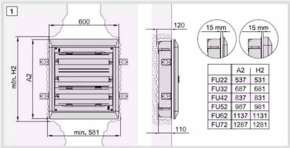
Flush holes dimensions are given by dims H2 and 581 mm in mounting instruction.
To ensure IP30 protection without door, a depth adjustment of the frame of 15 mm max. is recommended. Frame can be depth-adjusted until 23 mm above back panel by flush high-depth and more than 35 mm by flush low-depth.
For hollow-wall fixation, the kit VZ405N can be used. Minimal hole dimensions for hollow-wall mounting should be 551 mm width x total height - 30 mm (example: 1257 x 551 mm by FU72DN). See needed dimensions for flush hole below.
Flush fixation with hollow-wall kit VZ405N
Hollow-wall opening dimensions:

* = 3 rows
Flush fixation with side plates
Wall opening dimensions:

^* = 3 rows
Side plates to bend out with screwdriver
Kit VZ405N can be mounted horizontally or vertically until 30 mm wall thickness:
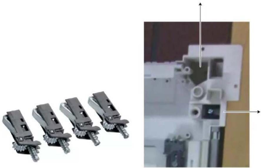
natural_image
Four black plastic electrical connectors arranged in a row, with an inset close-up showing internal components (no text or symbols visible)For hollow-wall installation it is recommended to support the lower edge of the enclosure by an accordingly designed opening, see following pictures. This ensures a good fixation over the years.


It is recommended to screw-in kit VZ405N with max. 2 Nm torque.
Another new feature in New VegaD flush enclosures is the possibility to cut out the plastic top/bottom part for inserting back panel in a hollow-wall with cable arrivals both sides top/bottom. It is only possible with an added opening in back panel. For this, a line has been designed on the plastic part (black line on the picture), so that the installer can follow it with a cutter and needs only to cut out plastic.
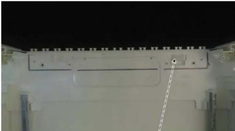
natural_image
Exterior view of a spacecraft module with visible structural elements and a pointer arrow (no text or symbols)As for surface enclosures, a mounting hole has been created in top/bottom plastic part from back panel for inserting a special water level. This level can be removed with a flat screwdriver. Water levels can be ordered by Market Area at production site in Blieskastel (Germany).

natural_image
Close-up of a white electronic device with a small illuminated component and mounting bracket (no visible text or symbols)8.3 Plaster protection in flush enclosures
Each flush enclosure is delivered with a plaster protection cardboard to fix on back panel.
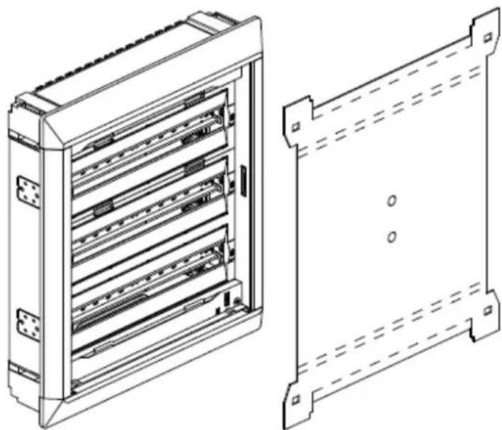
natural_image
Technical line drawing of an electrical cabinet with internal compartments and mounting brackets (no text or symbols)Cardboard protection is the same for flush low-depth and flush high-depth, but has to be bent and may have to be turned 180^ depending on flush depth to protect.

natural_image
3D rendering of a brown rectangular metal plate with mounting holes (no text or symbols)Flush high depth: bending to exterior side
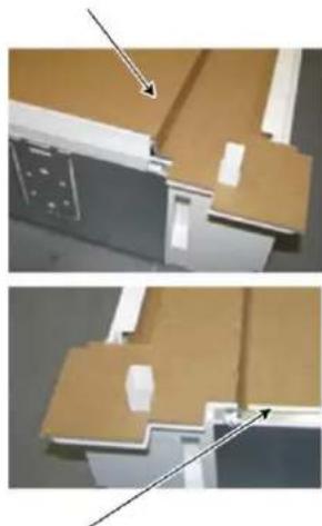
natural_image
Architectural detail showing two views of a building facade with door and window (no text or symbols)Flush low depth: bending to interior side

natural_image
Top-down view of a rectangular panel with white trim and red dashed lines, no visible text or symbolsred = bending line
2 x pre-perforated holes for finger taking
red = bending line

natural_image
White rollerboard with metal frame against a plain wall (no text or symbols visible)Example of flush low-depth enclosure protection against plastering
9 Technical data & certifications
Chapter index
Technical data 122
Power loss 123
Certifications 125
9.1 Technical data
Product fulfils the requirements of:
- DIN EN 61439-1:2012-06, EN 61439-1, IEC 61439-1:2011, VDE 0660-600-1:2012-06
- DIN EN 61439-3:2013-02, EN 61439-3, IEC 61439-3:2012, VDE 0660-600-3:2013-02
Rated operational voltage and frequency: 400 / 230 V AC, 50 Hz
Rated current: up to 160 A
Protection class: Class II
Protection degree (of surface enclosures): IP30 without door IP41 with door
Protection degree (of flush enclosures): IP30 without door IP40 with door
Indoor and/or outdoor installation for indoor installation
Data for air / leakage distance (clearance and creepage distances)
Overvoltage category: III
Pollution degree: 3
Rated insulation voltage (U): AC 400 V
IK Codes: IK08 with door IK07 without door
Glow wire test according DIN EN 60695:
- 960 °C for active parts
- 850 °C for flush plastic parts mounted behind wall-surface
- 750 °C for other parts (European minimum requirement is 650 °C, but French prescription for public buildings requires 750 °C)
PVC content:
All plastic parts from enclosure are halogen-free, excepted paper strip holders (PVC).
All FD accessories are halogen free except cable trunking FD00T1. Halogen free trunking exist under reference number FD00T2.
9.2 Power loss
9.2.1 Power loss for standard surface enclosures
| Enclosure | Permissible power loss P_perm for standard surface enclosure | ||||||||
| Type | Height H | Width B | Depth T | Surface mounted with temperature rise Δt | % Enclosure height | ||||
| 10 K | 15 K | 20 K | 25 K | 30 K | |||||
| mm | mm | mm | W | W | W | W | W | ||
| FD22... | 450 | 500 | 193 (Depth installation room 135 mm) | 15,0 | 24,8 | 35,4 | 46,8 | 58,7 | 75 |
| 17,9 | 29,7 | 42,4 | 56,0 | 70,2 | 50 | ||||
| FD32... | 600 | 17,7 | 29,4 | 42,0 | 55,4 | 69,5 | 75 | ||
| 22,2 | 36,8 | 52,7 | 69,5 | 87,2 | 50 | ||||
| FD42... | 750 | 20,6 | 34,1 | 48,8 | 64,4 | 80,7 | 75 | ||
| 26,5 | 43,8 | 62,7 | 82,7 | 103,8 | 50 | ||||
| FD52... | 900 | 23,5 | 38,9 | 55,6 | 73,4 | 92,1 | 75 | ||
| 30,6 | 50,7 | 72,6 | 95,8 | 120,1 | 50 | ||||
| FD62... | 1050 | 26,4 | 43,7 | 62,5 | 82,5 | 103,5 | 75 | ||
| 34,7 | 57,5 | 82,3 | 108,6 | 136,2 | 50 | ||||
| FD72... | 1200 | 28,5 | 47,1 | 67,4 | 89,0 | 111,6 | 75 | ||
| 39,3 | 65,0 | 93,0 | 122,7 | 154,0 | 50 | ||||
9.2.2 Power loss for surface enclosures with ventilation openings FD00P5
| Enclosure | Permissible power loss P_perm for enclosures with ventilation openings FD00P5 | ||||||||
| Type | Height H | Width B | Depth T | Surface mounted with temperature rise Δt | % Enclosure height | ||||
| 10 K | 15 | 20 K | 25 K | 30 K | |||||
| mm | mm | mm | W | W | W | W | W | ||
| FD22... | 450 | 500 | 150 (Depth installation room 135 mm) | 19,0 | 31,5 | 45,0 | 59,4 | 74,5 | 75 |
| 22,7 | 37,7 | 53,8 | 71,1 | 89,2 | 50 | ||||
| FD32... | 600 | 22,7 | 37,6 | 53,7 | 70,9 | 89,0 | 75 | ||
| 28,5 | 47,1 | 67,4 | 88,9 | 111,6 | 50 | ||||
| FD42... | 750 | 26,6 | 44,0 | 62,9 | 83,0 | 104,1 | 75 | ||
| 33,1 | 54,8 | 78,4 | 103,4 | 129,8 | 50 | ||||
| FD52... | 900 | 32,9 | 54,4 | 77,8 | 102,7 | 128,9 | 75 | ||
| 39,8 | 65,9 | 94,3 | 124,5 | 156,2 | 50 | ||||
| FD62... | 1050 | 39,8 | 66,0 | 94,4 | 124,6 | 156,3 | 75 | ||
| 48,6 | 80,5 | 115,2 | 152,0 | 190,7 | 50 | ||||
| FD72... | 1200 | 46,7 | 77,3 | 110,6 | 145,9 | 183,1 | 75 | ||
| 58,9 | 97,5 | 139,5 | 184,1 | 231,0 | 50 | ||||
9.2.3 Power loss for flush low-depth enclosures
Enclosure
Permissible power loss P_perm for flush low-depth enclosures
| Type | Height H | Width B | Depth T | Flush mounted with temperature rise Δt | % Enclosure height | ||||
| 10 K | 15 K | 20 K | 25 K | 30 K | |||||
| mm | mm | mm | W | W | W | W | W | ||
| FU22... | 536(450) | 586(500) | 150(Depth installation room 105 mm) | 10,9 | 18,0 | 25,7 | 33,9 | 42,5 | 75 |
| 13,2 | 21,9 | 31,2 | 41,2 | 51,7 | 50 | ||||
| FU32... | 686(600) | 13,2 | 21,9 | 31,3 | 41,3 | 51,8 | 75 | ||
| 16,7 | 27,7 | 39,7 | 52,3 | 65,7 | 50 | ||||
| FU42... | 836(750) | 15,6 | 25,8 | 36,9 | 48,7 | 65,7 | 75 | ||
| 20,2 | 33,5 | 47,9 | 63,2 | 79,3 | 50 | ||||
| FU52... | 986(900) | 18,0 | 29,8 | 42,6 | 56,3 | 70,6 | 75 | ||
| 23,6 | 39,1 | 55,9 | 73,8 | 92,6 | 50 | ||||
| FU62... | 1136(1050) | 20,4 | 33,8 | 48,4 | 63,8 | 80,1 | 75 | ||
| 27,0 | 44,7 | 63,9 | 84,3 | 105,8 | 50 | ||||
| FU72... | 1286(1200) | 22,8 | 37,8 | 54,1 | 71,4 | 89,5 | 75 | ||
| 30,3 | 50,2 | 71,7 | 94,7 | 118,8 | 50 | ||||
9.2.4 Power loss for flush high-depth enclosures
Enclosure
Permissible power loss P_perm for flush high-depth enclosures
| Type | Height H | Width B | Depth T | Flush mounted with temperature rise Δt | % Enclosure height | ||||
| 10 K | 15 K | 20 K | 25 K | 30 K | |||||
| mm | mm | mm | W | W | W | W | W | ||
| FU22... | 536(450) | 586(500) | 182(Depth installation room 105 mm) | 11,4 | 18,9 | 27,1 | 35,7 | 44,8 | 75 |
| 13,9 | 23,0 | 32,9 | 43,5 | 54,5 | 50 | ||||
| FU32... | 686(600) | 13,9 | 22,9 | 32,8 | 43,3 | 54,3 | 75 | ||
| 17,6 | 29,1 | 41,6 | 54,9 | 68,9 | 50 | ||||
| FU42... | 836(750) | 16,3 | 27,0 | 38,6 | 51,0 | 64,0 | 75 | ||
| 21,2 | 35,0 | 50,1 | 66,1 | 83,0 | 50 | ||||
| FU52... | 986(900) | 18,8 | 31,1 | 44,5 | 58,8 | 73,7 | 75 | ||
| 24,7 | 40,9 | 58,4 | 77,1 | 96,7 | 50 | ||||
| FU62... | 1136(1050) | 21,3 | 35,3 | 50,4 | 66,6 | 83,5 | 75 | ||
| 28,1 | 46,6 | 66,6 | 87,9 | 110,3 | 50 | ||||
| FU72... | 1286(1200) | 23,8 | 39,4 | 56,3 | 74,4 | 93,3 | 75 | ||
| 31,6 | 52,2 | 74,7 | 98,6 | 123,7 | 50 | ||||
9.3 Certifications
9.3.1 VDE certification for standard DIN/EN 61439-1/-3
is authorized to use for their product
the legally protected Marks as shown below for the types referred to on page 2 ff.
Tested and certified according to
DIN EN 61439-1 (VDE 0660-600-1):2012-06; EN 61439-1:2011
DIN EN 61439-3 (VDE 0660-600-3):2013-02; EN 61439-3:2012
EN 61439-1:2011
EN 61439-3:2012
VDE Testing and Certification Institute
VDE certificates are valid only when published on:
VDE
http://www.vde.com/zertifikat
http://www.vde.com/certificate

9.3.2 VDE CB certification for standard IEC 61439-1/-3

Test Report issued under the responsibility of:

| TEST REPORT IEC61439-3Low-voltage switchgear and controlgear assemblies -Part 3: Distribution boards intended to be operated by ordinary persons (DBO) |
| Report reference No. ......: 195161-CC3-1Date of issue......: 2014-06-03 Totalnumber of pages ......: 68 |
| Applicant's name ......: Hager Electro GmbH & Co. KGAddress......: Zum Gunterstal 6; 66440 Blieskastel; Germany |
| Test specification:Standard......: IEC 61439-3:2012 (First Edition) for use in conjunction with IEC 61439-1:2011 (Second Edition)Test procedure......: CB SchemeNon-standard test method......: N/A |
| Test Report Form No. ......: IEC61439_3A TestReport Form(s) Originator ....: VDEMaster TRF ......: Dated 2013-05Copyright © 2013 Worldwide System for Conformity Testing and Certification of Electrotechnical Equipment and Components (IECEE), Geneva, Switzerland. All rights reserved.This publication may be reproduced in whole or in part for non-commercial purposes as long as the IECEE is acknowledged as copyright owner and source of the material. IECEE takes no responsibility for and will not assume liability for damages resulting from the reader's interpretation of the reproduced material due to its placement and context.If this Test Report Form is used by non-IECEE members, the IECEE/IEC logo and the reference to the CB Scheme procedure shall be removed.This report is not valid as a CB Test Report unless signed by an approved CB Testing Laboratory and appended to a CB Test Certificate issued by an NCB in accordance with IECEE 02. |
| Test item description......: Low-voltage switchgear and controlgear assemblyTrade Mark......:hagerManufacturer ......: Hager Electro GmbH & Co. KG GermanyModel/Type reference ......: Vega D SerieRatings ......: AC 400 V, 160 A, IP 30, IP 40, IP 41, IK 05, T 40...-5°C |
VDE File No 1996500-1494-0004/195161
Testreport-195161-CC3-1.DOCX
9.3.3 LCIE certification for NF standard EN 61439-1/-3

LCIE
On the strength of the present decision notified by LCIE France mandated certification body, AFNOR Certification grants the right to use the NF Mark to the licence holder for the above mentioned products, within the frame of the general rules of the NF Mark and of the NF certification rules, as far as the regular checking and third party verifications of the production are satisfactory.
Rémi HANOT
Responsible de Certification Certification Officer® Capital

LCIE
Laboratoire Central
is authorized to use for their product
Empty enclosures for low-voltage switchgear and controlgear assemblies
the legally protected Marks as shown below for the types referred to on page 2 ff.
Tested and certified according to
DIN EN 62208 (VDE 0660-511):2012-06
EN 62208:2011
IEC 62208(ed.1)
VDE Testing and Certification Institute
Further conditions see overlear and following pages
Offenbach,2015-05-18
Blatt 1
Page
G. Heine
VDE certificates are valid only when published on:
http://www.vde.com/zertifikat
http://www.vde.com/certificate
VDE

10 List of References
| Reference | Pagee | Reference | Pagee | Reference | Pagee | Reference | Pagee |
| 1FD02701 | 102 | FD00S0 | 89 | FD52AN | 13 | FU42MN | 33 |
| 1FD05290 | 102 | FD00S1 | 89 | FD52BMN | 14 | FU42RN | 34 |
| 1FD05390 | 102 | FD00S2 | 90 | FD52BN | 16 | FU52ACN | 26 |
| 1FD05790 | 102 | FD00S3 | 90 | FD52CN | 17 | FU52AN | 27 |
| 1FD05890 | 102 | FD00S4 | 89 | FD52DN | 18 | FU52BN | 28 |
| 1FD05990 | 102 | FD00S5 | 90 | FD52GN | 19 | FU52CN | 29 |
| 1FD10390 | 102 | FD00T1 | 91 | FD52LN | 20 | FU52DN | 30 |
| 1FU05190 | 103 | FD00T2 | 92 | FD52MN | 21 | FU52GN | 31 |
| 1FU05290 | 103 | FD01A1 | 42 | FD52PN | 36 | FU52LN | 32 |
| 1FU05390 | 103 | FD01A2 | 42 | FD52RN | 22 | FU52MN | 33 |
| 1FU05490 | 103 | FD01K1 | 43 | FD52SN | 36 | FU52RN | 34 |
| 1FU05590 | 103 | FD02A1 | 45 | FD52TN | 36 | FU62ACN | 26 |
| 1FU05690 | 103 | FD02A2 | 45 | FD62ACN | 12 | FU62AN | 27 |
| 1FU06190 | 103 | FD02A3 | 46 | FD62AN | 13 | FU62BN | 28 |
| 1FU06290 | 103 | FD02C2 | 46 | FD62BN | 16 | FU62CN | 29 |
| 1FU06390 | 103 | FD02F1 | 47 | FD62CN | 17 | FU62DN | 30 |
| 1FU06490 | 103 | FD02F2 | 47 | FD62DN | 18 | FU62GN | 31 |
| 1FU06590 | 103 | FD02K1 | 48 | FD62GN | 19 | FU62LN | 32 |
| 1FU06690 | 103 | FD02K2 | 50 | FD62LN | 20 | FU62MN | 33 |
| 1FU06700 | 103 | FD02V2 | 50 | FD62MN | 21 | FU62RN | 34 |
| 1FU07201 | 103 | FD03A1 | 51 | FD62PN | 36 | FU72ACN | 26 |
| 1FU07301 | 103 | FD03Z1 | 51 | FD62RN | 22 | FU72AN | 27 |
| 5D020100 | 102 | FD22ACN | 12 | FD62SN | 36 | FU72BN | 28 |
| 5D020200 | 102 | FD22AN | 13 | FD62TN | 36 | FU72CN | 29 |
| 5D020300 | 102 | FD22BN | 16 | FD72ACN | 12 | FU72DN | 30 |
| 5D020400 | 102 | FD22CN | 17 | FD72AN | 13 | FU72GN | 31 |
| 5D020500 | 102 | FD22DN | 18 | FD72BN | 16 | FU72LN | 32 |
| 5D020600 | 102 | FD22GN | 19 | FD72CN | 17 | FU72MN | 33 |
| 5E460400 | 104 | FD22LN | 20 | FD72DN | 18 | FU72RN | 34 |
| BA7A100030 | 93, 92 | FD22MN | 21 | FD72GN | 19 | FZ142 | 95 |
| BA7A40030 | 93, 92 | FD22PN | 36 | FD72LN | 20 | FZ352 | 97 |
| BA7A60030 | 93, 92 | FD22RN | 22 | FD72MN | 21 | FZ442 | 96 |
| BA7A80030 | 93, 92 | FD22SN | 36 | FD72PN | 36 | FZ794 | 15 |
| FD00A1 | 52 | FD22TN | 36 | FD72RN | 22 | HA7100030 | 93, 92 |
| FD00A3 | 52 | FD32ACN | 12 | FD72SN | 36 | HA740030 | 93, 92 |
| FD00A4 | 52 | FD32AN | 13 | FD72TN | 36 | HA760030 | 93, 92 |
| FD00A5 | 53 | FD32BN | 16 | FU22ACN | 26 | HA780030 | 93, 92 |
| FD00B1 | 56 | FD32CN | 17 | FU22AN | 27 | KN06E | 82 |
| FD00B2 | 58 | FD32DN | 18 | FU22BN | 28 | KN10E | 82 |
| FD00C1 | 59 | FD32GN | 19 | FU22CN | 29 | KN14E | 82 |
| FD00C2 | 59 | FD32LN | 20 | FU22DN | 30 | KN18E | 82 |
| FD00C3 | 60 | FD32MN | 21 | FU22GN | 31 | KN22E | 82 |
| FD00C4 | 60 | FD32PN | 36 | FU22LN | 32 | KN26E | 82 |
| FD00C5 | 60 | FD32RN | 22 | FU22MN | 33 | KN99E | 82 |
| FD00F1 | 71 | FD32SN | 36 | FU22RN | 34 | UN02FN | 104 |
| FD00F2 | 78 | FD32TN | 36 | FU32ACN | 26 | UN03FN | 104 |
| FD00F3 | 80 | FD32ZN | 23 | FU32AN | 27 | UN04FN | 104 |
| FD00G1 | 63 | FD42ACN | 12 | FU32BN | 28 | UN05FN | 104 |
| FD00H1 | 81 | FD42AN | 13 | FU32CN | 29 | UN06FN | 104 |
| FD00H2 | 81 | FD42BMN | 14 | FU32DN | 30 | UN07FN | 104 |
| FD00M1 | 61 | FD42BN | 16 | FU32GN | 31 | UZ01V1 | 101, 101 |
| FD00M2 | 61 | FD42CN | 17 | FU32LN | 32 | UZ25V1 | 101, 101 |
| FD00M3 | 62 | FD42DN | 18 | FU32MN | 33 | UZ25V2 | 101, 101 |
| FD00M4 | 62 | FD42GN | 19 | FU32RN | 34 | VZ00ASF | 15 |
| FD00P1 | 83 | FD42LN | 20 | FU42ACN | 26 | VZ405N | 116 |
| FD00P2 | 84 | FD42MN | 21 | FU42AN | 27 | VZ741 | 84, 88 |
| FD00P3 | 84 | FD42PN | 36 | FU42BN | 28 | ZZ41SF | 105 |
| FD00P4 | 85 | FD42RN | 22 | FU42CN | 29 | ZZ42BS | 102, 103 |
| FD00P5 | 86, 15 | FD42SN | 36 | FU42DN | 30 | ||
| FD00P6 | 87 | FD42TN | 36 | FU42GN | 31 | ||
| FD00Q1 | 82 | FD52ACN | 12 | FU42LN | 32 |
11 Index
A
About this manual • 4
Accessories • 40
ACN Version • 12, 26
AN Version • 13, 27
B
BA7A/HA7... = vertical trunkings sideways • 93
BMN Version • 14
BN Version • 16, 28
C
Certifications • 125
CN Version • 17, 29
D
Dimensions and weights of enclosures • 110
DN Version • 18, 30
Door frames as spare parts • 102
Door hinges • 39
Door mounting into enclosure frames • 38
Doors for flush and surface enclosures • 35
E
Enclosure type labels • 109
Equipment units • 42
External dimensions • 10, 25, 36
F
FD00A... = Standard Accessories • 52
FD00B... = Side Brackets for vertical cables • 56
FD00C... = Covers • 59
FD00F... = Fixation kit • 71
FD00G... = Gallery Adapter for VegaD surface versions (FD...) • 63
FD00H... = DIN rail Holders for equipment units • 81
FD00M... = Mounting plates • 61
FD00P... = Plate for cable entry • 83
FD00Q... = Quick-Connect & terminal holder • 82
FD00S... = Serrure (closing system) • 89
FD00T... = Trunking • 91
FD01.. = Equipment units, height 150 mm • 42
FD02.. = Equipment units, height 300 mm • 45
FD03.. = Equipment units, height 450 mm • 51
Flush enclosures with door (FU...N) • 113
Flush enclosures without door (FU...N) • 112
Flush-mounting for flush enclosures • 116
For your safety • 6
FZ... = Univers cable storage and hiding box • 94
G
GN Version • 19, 31
L
Labels • 109
Labels on cardboard packaging • 109
LCIE certification for NF standard EN 61439-1/-3 • 127
List of References • 129
LN Version • 20, 32
M
Market-specific product ranges • 12, 26
MN Version • 21, 33
N
Naming rules • 41
P
Packaging and dimensions of enclosures • 106
Packaging use at the workshop or at the construction site • 108
Pictures of packaging • 107
Plaster protection in flush enclosures • 119
Power loss • 86, 123
Power loss for flush high-depth enclosures • 124
Power loss for flush low-depth enclosures • 124
Power loss for standard surface enclosures • 123
Power loss for surface enclosures with ventilation openings FD00P5 • 123
Product range by New VegaD flush • 24
Product range by New VegaD surface • 9
Proper use • 7
R
Requirements for authorised personnel • 8
RN Version • 22, 34
S
Single and spare parts • 52
Subject of the manual • 5
Surface enclosures with door (FD...N) • 111
Surface enclosures without door (FD...N) • 110
T
Technical data • 122
Technical data & certifications • 121
U
USP • 5, 43, 56, 76, 85, 87
UZ...V. = Univers N cable brackets • 101
V
VDE CB certification for standard IEC 61439-1/-3 • 126
VDE certification for standard DIN/EN 61439-1/-3 • 125
VDE certification for standard DIN/EN/IEC 62208 for empty enclosures • 128
Vertical uprights and fixation accessories • 104
W
Wall fixation • 114
Wall-mounting for surface enclosures • 115
Warranty and Liability • 5
Z
ZN Version • 23
:hager
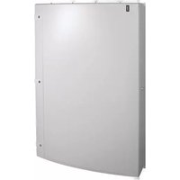


- Technical Manual New VegaD
- Table of contents
- About this manual 4
- For your safety 6
- Product range by New VegaD surface 9
- Product range by New VegaD flush
- Doors for flush and surface enclosures
- Accessories
- Single and spare parts 52
- Packaging and dimensions of enclosures 106
- Wall fixation 114
- Technical data & certifications 121
- List of References 129
- Index 130
- About this manual
- Chapter index
- Subject of the manual
- Warranty and Liability
- Liability note
- For your safety
- Proper use
- Fixed indoor installation/wall mounting
- Misuse
- Limitation of operating areas
- Requirements for authorised personnel
- Product range by New VegaD surface
- External dimensions
- Market-specific product ranges
- ACN Version
- AN Version
- BMN Version
- BN Version
- CN Version
- DN Version
- GN Version
- LN Version
- MN Version
- RN Version
- ZN Version
- External dimensions
- Market-specific product ranges
- ACN Version
- AN Version
- BN Version
- CN Version
- DN Version
- GN Version
- LN Version
- MN Version
- RN Version
- External dimensions
- Door mounting into enclosure frames
- Door hinges
- Naming rules
- Examples
- Equipment units
- FD01.. = Equipment units, height 150 mm
- FD01A1: Kit for 1 distribution DIN rail (430 x 150 x 147 mm)
- FD01A2: Kit for 1 depth-adjustable DIN rail (430 x 150 x 147 mm)
- FD01K1: Kit for 160 A MCCB horizontal 3 and 4 poles (430 x 150 x 147 mm)
- FD02.. = Equipment units, height 300 mm
- FD02A1: Kit with 2 distribution DIN rails (430 x 300 x 147 mm)
- FD02A2: Kit with 2 depth-adjustable DIN rails (430 x 300 x 147 mm)
- FD02A3: Kit with 1 depth-adjustable DIN rail and 1 standard DIN rail (430 x 300 x 147 mm)
- FD02C2: Kit with depth-adjustable perforated plate (430 x 300 x 147 mm)
- FD02F1: Kit with french DB plate (for Disjoncteur de Branchement) (430 x 300 x 147 mm)
- FD02F2: Kit with french DB + linky meter plate (430 x 300 x 147 mm)
- FD02K1: Kit for 160 A MCCB vertical 3 and 4 poles (430 x 300 x 147 mm)
- FD02K2: Kit for 250A MCCB (In 160 A) vertical 3 and 4 poles (430 x 300 x 147 mm)
- FD02V2: Kit for motorized change over switch 160 A (430 x 300 x 147 mm)
- FD03.. = Equipment units, height 450 mm
- FD03A1: Kit with 3 distribution DIN rails (430 x 450 x 147 mm)
- FD03Z1: Kit for meter + main switch three-phase (430 x 450 x 147 mm)
- Single and spare parts
- FD00A... = Standard Accessories
- Partition IP2X to mount in 3 different positions:
- FD00B... = Side Brackets for vertical cables
- FD00C... = Covers
- FD00C3: 300 mm 1x slotted cover 24 mod.
- FD00C4: 150 mm 1x slotted cover 24 mod.
- FD00C5: 150 mm plain cover 24 mod.
- FD00M... = Mounting plates
- FD00M1: 215 mm ∅ 3,2 perforated plate (434 x 215 x 1,2 mm)
- FD00M2: 290 mm plain plate (434 x 290 x 2 mm)
- FD00M3: 140 mm ∅ 3,2 perforated plate (434 x 140 x 1,2 mm)
- FD00M4: 140 mm plain plate (434 x 140 x 2 mm)
- FD00G... = Gallery Adapter for VegaD surface versions (FD...)
- Gallery compatibility
- Protection cover compatibility
- Protective cover
- Mounting instruction
- FD00F... = Fixation kit
- FD00F1: Fixation kit (for surface versions only)
- Vertical association (first enclosure already wall-mounted)
- Step
- Action
- Horizontal association (first enclosure already wall-mounted)
- Step Action
- 3
- 4
- 5
- 6
- 7
- 8
- Horizontal association or vertical association with both enclosures on table
- FD00F2: Fixation kit (for surface versions only)
- 2
- FD00F3: Bar for cables fixation (for surface and flush versions)
- FD00H... = DIN rail Holders for equipment units
- FD00Q... = Quick-Connect & terminal holder
- Jumper for Earth Terminal Blocks
- FD00P... = Plate for cable entry
- FD00P2: 1x Plate for cable entry (Slider) with 2 water-proof flanges IP41 (for surface, flush high-depth and flush low-depth versions)
- FD00P3: 1x Plate for cable entry (Slider) with tube openings (for surface, flush high-depth and flush low-depth versions)
- FD00P4: 2x Plate for cable entry (Side plate) (for surface versions only)
- FD00P5: 2x Side plate for aeration (for surface versions only)
- FD00P6: Side plate for cable entry with M40 flange (for surface versions only)
- VZ741: New VegaD cable entry flange IP41
- FD00S... = Serrure (closing system)
- FD00S2 / FD00S3 / FD00S5: special closing system triangle 7 mm / square 7 mm / two-way 3 mm
- FD00T... = Trunking
- FD00T1: 4x horizontal cable tray kit 80x30 with 9 mm interslot distance in PVC
- FD00T2: horizontal trunking kit 80x30 with 9 mm interslot distance halogen-free
- BA7A/HA7... = vertical trunkings sideways
- FZ... = Univers cable storage and hiding box
- Mounting examples:
- UZ...V. = Univers N cable brackets
- Door frames as spare parts
- Vertical uprights and fixation accessories
- Vertical uprights as spare part
- ZZ41SF: Lock nuts for vertical upright fixing as spare part
- Packaging and dimensions of enclosures
- Pictures of packaging
- Packaging use at the workshop or at the construction site
- Surface enclosure packaging:
- Flush low- and high-depth enclosure packaging:
- Labels
- Labels on cardboard packaging
- Enclosure type labels
- Dimensions and weights of enclosures
- Wall fixation
- Wall-mounting for surface enclosures
- Flush-mounting for flush enclosures
- Plaster protection in flush enclosures
- Technical data & certifications
- Technical data
- Power loss
- Power loss for standard surface enclosures
- Power loss for surface enclosures with ventilation openings FD00P5
- Power loss for flush low-depth enclosures
- Power loss for flush high-depth enclosures
- Certifications
- VDE certification for standard DIN/EN 61439-1/-3
- VDE CB certification for standard IEC 61439-1/-3
- LCIE certification for NF standard EN 61439-1/-3
- Index
- A
- B
- C
- D
- E
- F
- G
- L
- M
- N
- P
- R
- S
- T
- U
- V
- W
- Z
- :hager
Brand : HAGER
Model : ZZ42BS
Category : Uncategorized