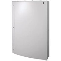
JF406B - Uncategorized HAGER - Free user manual and instructions
Find the device manual for free JF406B HAGER in PDF.


| Product Type | Panelboard (Distribution Board) |
| Brand | Hager |
| Model | JF406B |
| Dimensions (H x W x D) | 1250 x 900 x 220 mm |
| Weight | 55 kg |
| Rated Operational Voltage | 415 V AC 50 Hz |
| Rated Insulation Voltage | 690 V AC |
| Rated Impulse Withstand Voltage | 6 kV |
| Rated Current of Assembly (InA) | 400 A |
| Rated Current of Outgoing Circuits (Inc) | 16 A – 125 A |
| Rated Short-Time Withstand Current (Icw) | 35 kA / 1 s |
| Rated Conditional Short-Circuit Current (Icc) | 25 kA |
| Degree of Protection | IP30 (door closed), IP2XC (door open with blanks) |
| Mechanical Impact Protection | IK05 |
| Mounting Type | Wall-mounted, surface type, enclosed |
| Indoor Use Only | Yes |
| Pollution Degree | 3 |
| EMC Classification | Environment B |
| Form of Separation | Form 3b (with outgoing shrouds fitted) |
| Number of Ways | 6 |
| Warranty | 24 months |
| Installation Standards | BS 7671 (IET Wiring Regulations), Electricity at Work Regulations |
| Incoming Device | 400 A 3-pole MCCB incomer kit (included) |
| Accessories Available | Blanking plates, endplate, digital meter pack, DIN rail boxes, spreader boxes, door kits |
| Maintenance | Periodically check and tighten all electrical connections to specified torque; ensure terminal shrouds are fitted after installation |
Frequently Asked Questions - JF406B HAGER
User questions about JF406B HAGER
0 question about this device. Answer the ones you know or ask your own.
Ask a new question about this device
Download the instructions for your Uncategorized in PDF format for free! Find your manual JF406B - HAGER and take your electronic device back in hand. On this page are published all the documents necessary for the use of your device. JF406B by HAGER.
USER MANUAL JF406B HAGER
Invicta 3 Panelboard
Installation instructions
natural_image
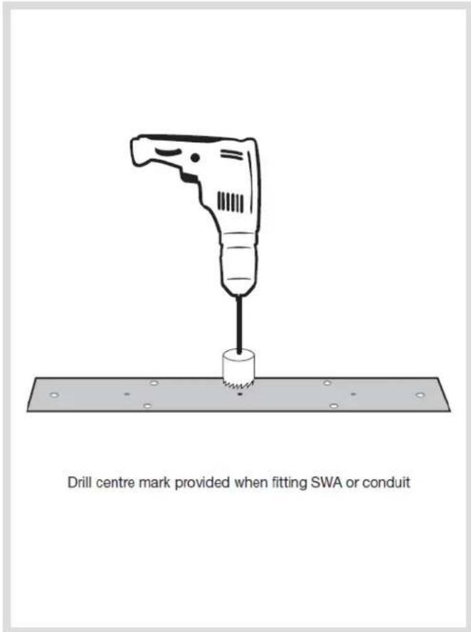
Line drawing of a hand tool with a saw and blade (no text or symbols)All product(s) must be installed by a suitably competent electrician giving consideration to their intended use and in accordance with the current edition of BS 7671 (IET Wiring Regulations).
The Electricity at Work regulations and the Health and Safety at Work Act shall be complied with.
Only equipment and arrangements specified in Hager's technical documentation / catalogue shall be used
Install in the vertical plane only.
Notice:
To prevent potential overheating from loose connections the installer shall check connections are tightened to the torque levels stated in these instructions prior to energising this board. This check should include factory made connections which may have loosened in transit.


natural_image
Illustration of an open cabinet with door, doors, and internal compartments (no text or symbols)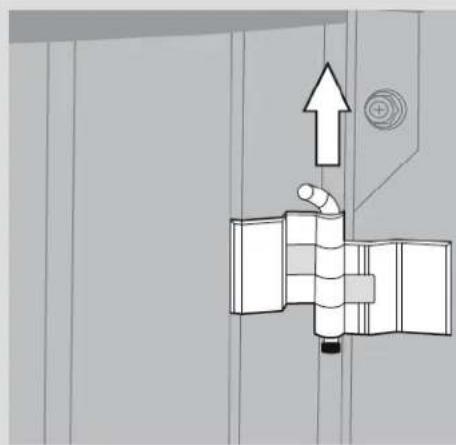
natural_image
Pure mechanical diagram showing a pipe connection with an upward arrow, no text or symbols present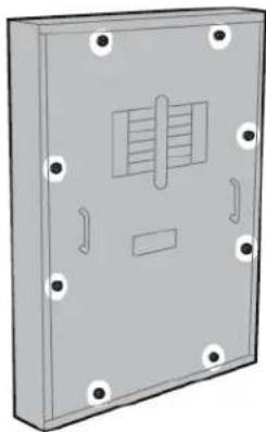
natural_image
3D rendering of a rectangular electronic device with mounting holes and internal slot (no text or symbols)


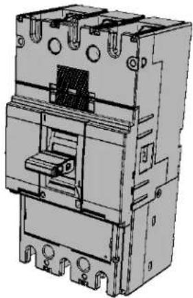
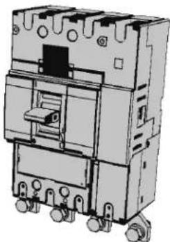
JF4 3 Pole 400A MCCB/MCS incomer kit
400A Incomer kits contain:
- 3 x Phase extension links
- 3 x spreader links
- 6 x Phase link Allen fixing bolts and washers (M10)
- 4 x Long fixing screws
- 1 x MCCB/ MCS
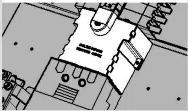
• Terminal covers
Ensure terminal shrouds are removed before fitting.
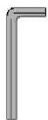
17 mm A/F

8 mm HEX
natural_image
Technical line drawing of an electrical contactor or shock absorber with mounting holes and internal components (no text or symbols)1
Fit the MCCB to the pan assembly with fixing screws provided
Fit the extension links (A) to the MCCB with the Allen fixings
Fit the spreader links to the bottom of the |MCCB (B) with the fixings provided


natural_image
Technical diagram of a mechanical assembly with labeled parts and directional arrows (no readable text or symbols)Connect the extension links to the busbar with the 3 x M10 coach bolts. Hand tighten at this stage. Now tighten the MCCB fixing screws to secure the MCCB to the pan assembly.
Once the MCCB is in place tighten all M10 electrical connections to 22Nm Fit the terminal shrouds
natural_image
Architectural floor plan sketch showing room layouts and structural elements (no text or labels)JF4 4 Pole 400A MCCB/MCS incomer kit
400A 4 pole incomer kits contain:
- 3 x Line extension links
- 1 x Neutral link
- 4 x spreader links
- 8 x Phase link Allen fixing bolts and washers (M8)
- 4 x Long fixing screws
- 1 x MCCB/ MCS
•Terminal covers
Ensure terminal shrouds are removed before fitting.
13mm A/F

6mm HEX

natural_image
Technical illustration of an electrical contactor device with multiple terminals and mounting holes (no text or symbols)
Remove the busbar shield. Remove the two M8 bolts that secure the neutral swing link (A). Replace the bottom M8 bolt.
The top bolt is used to connect the 4 pole neutral link. The swing link is not required for the 4 pole incomer.
Fit the MCCB to the pan assembly with the fixings provided
Fit the spreader links to the bottom of the IMCCB (B) with the fixings provided

natural_image
Technical diagram of an electronic circuit board layout with no visible text or symbolsZD0740 issue 3a
Connect the extension links to the busbar with the 3 x M10 coach bolts the M8 coach bolts. Hand tighten at this stage.
Connect the neutral link with the M8 coach bolts. Hand tighten at this stage
Now tighten the MCCB fixing screws to secure the MCCB to the pan assembly.
Once the MCCB is in place tighten all M10 electrical connections to 22Nm. Tighten all M8 connections to 13Nm
Fit the terminal shrouds

natural_image
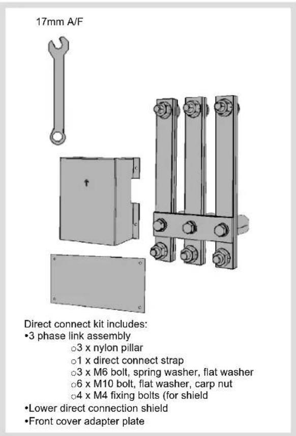
Pure technical line drawing of a mechanical assembly without any text, numbers, or symbolsJF4 3 Pole direct connect incomer kit


Only equipment and arrangements specified in Hager's technical documentation / catalogue shall be used.

natural_image
3D diagram showing a connector pin layout with an arrow pointing to a device component (no text or symbols present)Fitting Single Pole MCCBs
Single pole MCCB contains:
- 2 x Fixing bolts
- 2 x Spring washers
- 2 x Single fixing plates
- 2 x Double fixing plates
Mount the MCCB on to the busbar finger with the red trip button facing inwards. Fix the device to the pan assembly using the fixings provided
See single pole instructions for more information
Tighten electrical connections to 6.6Nm

natural_image
Technical diagram showing a 3D mechanical assembly with directional arrows indicating flow or movement, alongside a detailed close-up of the component (no text or symbols present)Fitting Three Pole MCCBs
Three pole MCCB contains:
- 2 x Fixing bolts
- 2 x Spring washers
- 2 x Flat washers
Mount the MCCB on to the busbar finger with the red trip button facing inwards. Fix the device to the pan assembly using the fixings provided.
Use the Auxiliary/Shunt trip accessory channel (▲) to dress cables from these accessories
See three pole instructions for more information Tighten electrical connections to 6.6Nm
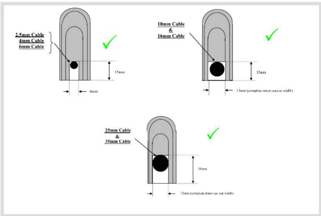
Achieving Form 3b type 2 on x160 frame MCCB outgoing
Using HYA021H Terminal cover: Outgoing Devices x160 Frame only (125A) Cut Out Dimensions are shown below to achieve IPXXB (Form 3b type 2)
Interface characteristics
Rated & operational voltage ( U_n / U_e )
415V a.c. 50Hz
Rated insulation voltage (U)
690V a.c. 50Hz
Rated impulse withstand voltage ( U_imp ) 6kV
Rated current of the Assembly (InA)
JF4xxx 400A ^1
^1 or rating of incoming circuit / incomer kit whichever is lower
Rated current of an Outgoing circuit (Inc)
MCCB 16A - 125A (marked rated current on device)
Rated short-time withstand current of the main busbars (Icw)
35kA/1 sec ^1 with equipment and arrangements specified in Hager's technical documentation / catalogue.
^1 Current limitation characteristics specified in Hager's technical documentation / catalogue
Rated conditional short-circuit current of the PSC-ASSEMBLY (I_cc)
25kA ^1 with equipment and arrangements specified in Hager's technical
documentation / catalogue.
^1 Current limitation characteristics specified in Hager's technical documentation / catalogue
Protection against electric shock
PSC-ASSEMBLY shall be installed in an electrical system
conforming to IEC 60364 / BS 7671
Rated diversity factor (RDF) / Values of assumed loading
6 way - 8 way = 0.7
12 way - 18 way = 0.6
Note: RDF only applies to continuously and simultaneously loaded circuits.
Rated frequency (fn)
50 Hz
Pollution degree
3
Types of system earthing for which the PSC-ASSEMBLY is designed
TNC-S, TN-S and TT when installed in an electrical system conforming to BS 7671
Indoor use only
Stationary PSC-ASSEMBLY
Degree of protection
IP30 with Door Closed
IP2XC with Door Open and compliment of outgoing devices and or blanks fitted.
Intended use
Not Intended to be operated by ordinary persons.
Electromagnetic compatibility (EMC) classification
EMC Environment B
External design
Wall-mounted, surface type, enclosed assembly.
Mechanical impact protection
IK05
The type of construction
Fixed parts
The type of Electrical connections of functional units
FF = Fixed connections
Forms of separation
Form 3b when outgoing shrouds are fitted. A competent person must always complete a risk assessment and appropriate test to confirm that, the un-shrouded neutral within the Panelboard is not a hazardous live part. In particular, The Electricity at Work
Regulations 1989 including any amendments must be complied with.
| Designation | H | W | D | Weight (Kg) |
| JF406B(G) | 1250 | 900 | 220 | 55 |
| JF408B(G) | 1250 | 900 | 220 | 56 |
| JF412B(G) | 1400 | 900 | 220 | 64 |
| JF416B(G) | 1550 | 900 | 220 | 72 |
| JF418B(G) | 1700 | 900 | 220 | 78 |
Warranty
This distribution board is offered with a 24 month warranty against defective material or manufacture. If a warranty claim is necessary, please call the technical support number given at the bottom of the page and we will be pleased to help.
JF4 Incomer Kits
| Cat Ref. | No of Poles | Description + Rated Current of Incoming Circuit |
| JF443BM | 3 | MCCB Incomer Kit 400A |
| JF444BM | 4 | MCCB Incomer Kit 400A |
| JF443BS | 3 | Isolator Incomer Kit 400A |
| JF444BS | 4 | Isolator Incomer Kit 400A |
| JF444BD | 4 | Direct Connection Kit 400A |
JF4 Accessories
| Cat Ref. | Description |
| JF003BP | 3P BLANKING PLATE 250A FRAME |
| JN001BP | 1P BLANKING PLATE 125A FRAME |
| JFPLATE | JF4 & 8 ENDPLATE |
| JF403BA | MULTI FUNCT DIGITAL METER PACK |
| JF801E | SMALL DIN RAIL BOX, PLAIN DOOR |
| JF801EG | SMALL DIN RAIL BOX GLAZED DOOR |
| JF803E | LARGE DIN RAIL BOX, PLAIN DOOR |
| JF803EG | LARGE DIN RAIL BOX, GLAZED DOOR |
| JF805E | SMALL SPREADER BOX (NO DOOR) |
| JF805DK | DOOR KIT FOR SMALL SPREADER BOX |
| JF806E | LARGE SPREADER BOX (NO DOOR) |
| JF806DK | DOOR KIT FOR LARGE SPREADER BOX |
| D.B No: | Voltage: | Supplied From: |
| Supply cable mm: | Incoming Isolator: | Ze: | P.S.C. |
| CIR | AMPS | TYPE | CABLE MM | C.P.C MM | LOCATION DESCRIPTION |
ZD0740 issue 3a
Panel board circuit designation chart
| D.B No: | Voltage: | Supplied From: |
| Supply cable mm: | Incoming Isolator: | Ze: | P.S.C. |
| CIR | AMPS | TYPE | CABLE MM | C.P.C MM | LOCATION DESCRIPTION |
Hager Ltd.
Hortonwood 50
Telford
Shropshire
TF1 7FT
National Sales Hotline 01952 675612
National Tech Support helpline 01952 675689


Brand : HAGER
Model : JF406B
Category : Uncategorized