VB-11 - Flash Drive Bolt - Free user manual and instructions
Find the device manual for free VB-11 Bolt in PDF.


| Product Type | Bare-bulb flash unit |
| Model | VB-11 |
| Brand | Bolt |
| Dimensions | 8.07 x 3.54 x 2.75 in (205 x 90 x 70 mm) |
| Weight | 1.5 lb (0.68 kg) |
| Power Output | 180 W/s |
| Guide Number | 196 ft (60 m) at ISO 100 with reflector |
| Flash Coverage | 28 mm (with reflector) |
| Flash Duration | 1/300 to 1/10,000 second |
| Power Output Range | 1/1 to 1/128 in 1/3-stop increments |
| Recycle Time | 0.05 – 2.6 seconds with Bolt PP-400DR power pack |
| Flash Modes | Manual, Optical Slave (S1/S2), Repeat (Stroboscopic) |
| Triggering Options | Hot shoe, PC sync, 3.5 mm jack, optical slave, dedicated remote |
| Head Tilt | 90° up to -15° down |
| Head Swivel | 135° right, 180° left |
| Display | 1.75-inch backlit LCD |
| AF-Assist | Yes, with AF-Assist light |
| Audio Indicator | Audible beep when fully recycled |
| Power Source | External power pack (sold separately) |
| Mounting | Shoe mount (built-in) and separate Stand/Tripod mount (1/4-20 thread) |
| Accessories Included | Reflector, diffuser, retaining ring, power cable, protective pouch, stand/tripod mount |
| Flashtube | User-replaceable (VB-11-FT) |
| Safety Protection | Thermal protection mode (auto-disables when overheated) |
| Warranty | One-year limited warranty |
Frequently Asked Questions - VB-11 Bolt
User questions about VB-11 Bolt
0 question about this device. Answer the ones you know or ask your own.
Ask a new question about this device
Download the instructions for your Flash Drive in PDF format for free! Find your manual VB-11 - Bolt and take your electronic device back in hand. On this page are published all the documents necessary for the use of your device. VB-11 by Bolt.
USER MANUAL VB-11 Bolt
natural_image
Illustration of a black Bolt flashlight with red buttons, shown from front and side (no text or symbols on the device itself)Introduction
Thank you for choosing a Bolt VB-Series Bare-Bulb flash. These flashes are designed for photography professionals and enthusiasts interested in a portable high-power light source with 360-degree exposure and versatile light shaping options.
Using the included reflector and diffuser, the high output from your VB-Series flash can be focused and softened to create beautiful contrasted light. The flashes can also accept other various light modifiers to create your ideal shooting conditions. Additionally, the bare-bulb flash units can be attached and secured to a myriad of stands and mounts, simplifying the setup and use of the device.
• High power (360 W/s on VB-22, 180 W/s on VB-11)
• 1/1 to 1/128 flash output
- User-replaceable flashtube
• Stroboscopic and Slave modes
- Tilt and swivel head: -15^ down, 90^ up, 135^ right, and 180^ left
- Versatile accessory mount
- Five different triggering options
• 1.75" backlit LCD screen
• Auto-focus assist function
• Reflector and diffuser included
Contents
Introduction 2-3
Overview 6-9
Warnings 10-11
Using the Flash
Installing and Replacing the Flashtube 12-13
Powering the Flash....14-15
Mounting the Flash....16-17
Setting the Flash Power 18
Triggering the Flash 19
AF-Assist Mode 20
Audio Function 20
Optical Slave Triggering Mode 21
Repeat Mode 22-23
Modifying the Light Output
Tilt and Swivel 24-25
Lighting Effects 26
Using the Reflector and Diffuser 27
Troubleshooting 28-29
Specifications 30
Repeat Mode Reference Chart 31
Recommended Accessories 32-35
Limited Warranty ....36 (Back Cover)
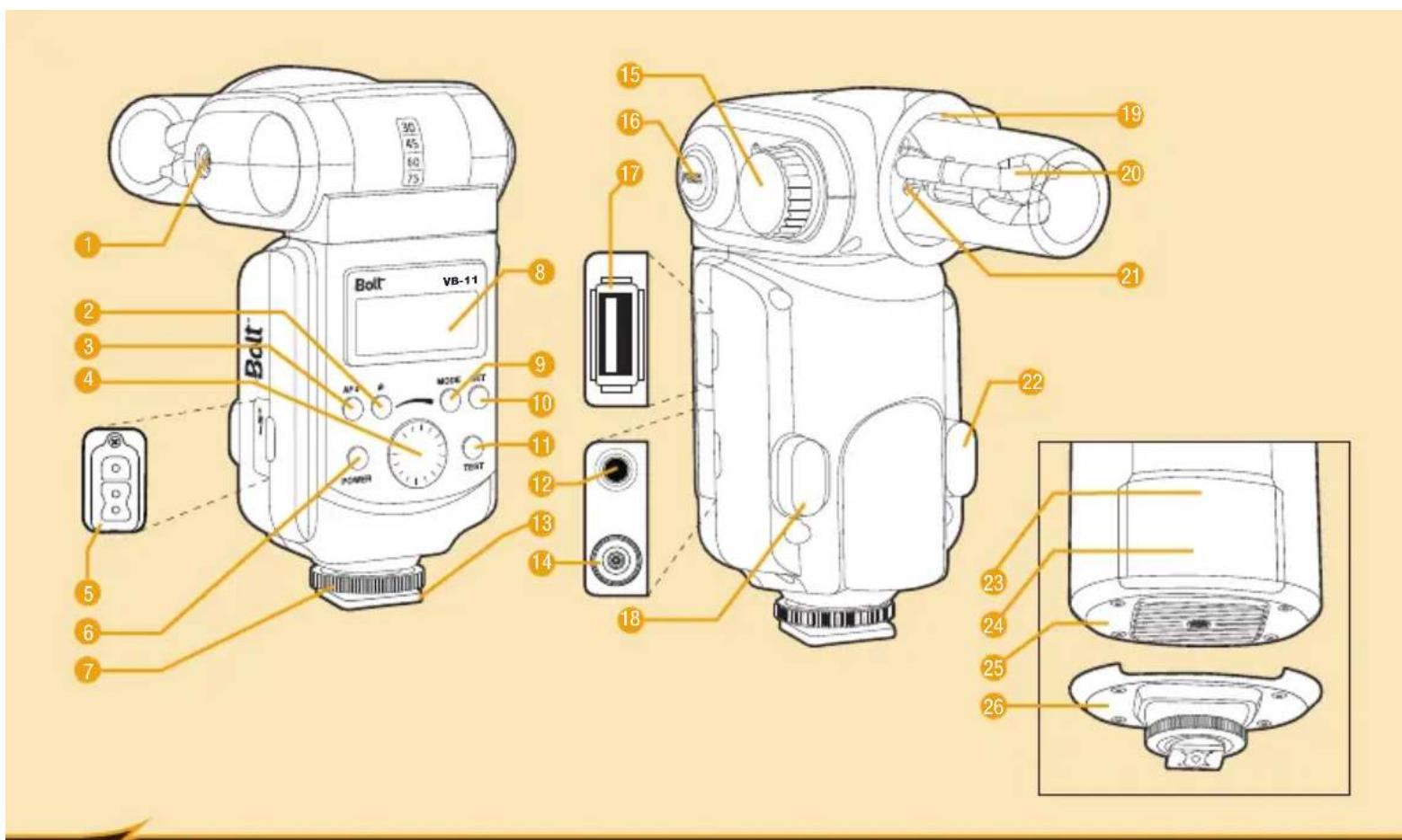
Overview
- Umbrella Bracket Mounting Hole
- Audio Button
- AF-Assist Button
- Selection Dial
- Power Socket
- Power Button
- Shoe Locking Wheel
- LCD Display
- Mode Button
- Set Button
- Test Button
- Sync Cord Jack
- Mounting Foot
- PC Sync Socket
- Accessory Locking Knob
- Position Release Button
-
Wireless Control Port
-
AF-Assist Light
- Accessory Mount
- Flashtube
- Flashtube Socket
- Optical Slave Sensor
Additional VB-22 Parts:
- AF-Assist Light
- Optical Slave Sensor
- Stand Mounting Foot
- Shoe Mounting Foot
natural_image
Illustration of two types of medical or electrical components: a coiled cord with labeled parts (39 and 40) and a bandage (no text or symbols beyond labels)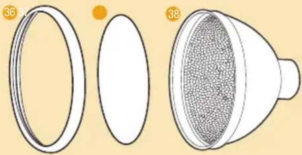
natural_image
Diagram showing a funnel with internal mesh structure and two circular components, labeled 36 and 38 (no text or symbols on the diagram itself)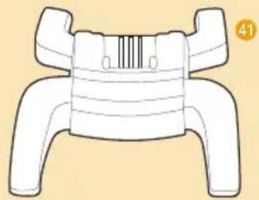
natural_image
Line drawing of a mechanical component with no visible text or symbolsLCD:
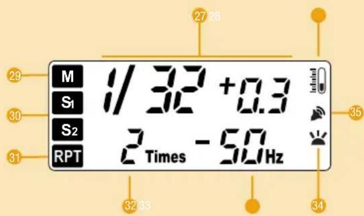
- Power Output Indicators
- Thermal Protection Mode
- Manual Mode
- Slave Modes
- RPT Mode
- RPT Times Indicator
- RPT Frequency Indicator
- AF-Assist Indicator
- Audio Indicator
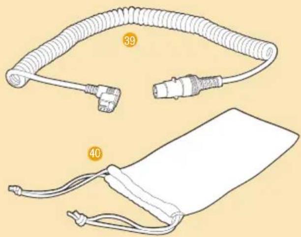
Included Accessories:
- Retaining Ring
- Diffuser
- Reflector
- Power Cable
- Protective Pouch
- Stand/Tripod Mount
Warnings
Please read the following instructions before using this product to ensure safe use and to help prevent damage to your flash or injury to yourself or others. Keep this manual in a safe place.
- Do not fire the flash at close range directly into the eyes of people or animals. This can cause damage to the retina and may even lead to blindness.
- Do not disassemble or attempt to repair this product yourself. High-voltage components inside can produce a hazardous electric shock.
- Keep this product and its accessories out of the reach of children.
- Use only the power sources specified in this manual.
- Always switch the flash off before installing or removing a power source.
- Do not use or store your VB-Series Bare Bulb Flash in flammable conditions (such as environments containing flammable gases or liquid chemicals). This can damage the flash, start a fire, or cause an electric shock.
-
Do not clean the unit with agents containing corrosive or flammable substances such as paint thinner, benzene, or nail polish remover.
-
This product is not water resistant. Keep it away from rain, snow, humidity, and general moisture.
- Should the unit sustain physical damage, do not touch any exposed interior metal parts. If touched, they may generate an electric shock or cause a malfunction. Promptly remove the power source and take the product to an authorized service center for repair.
- If you detect excessive heat, smoke, or a burning smell coming from the flash, immediately stop operation and remove the power source to prevent the product from igniting or melting. Take the product to an authorized service center for repair.
- Do not drop or otherwise cause a strong physical impact to the unit, as this can cause a malfunction that may cause it to explode or ignite.
- Remove all power sources from the unit before long-term storage in order to prevent the product from igniting or leaking corrosive liquids.
- Do not store or use the product at temperatures above 104^ (40°C).
- Keep the power socket clean and free of corrosion and direct. Do not touch it with your fingers. Corrosive elements on the contacts can damage the unit and prevent it from functioning properly. The power socket may be cleaned with isopropyl alcohol on a cotton swab.
- All images are for illustrative purposes only.
Using the Flash
INSTALLING THE FLASHTUBE
Before installing the flash tube, ensure the device is switched off and the power cord disconnected from the unit. Additionally, remove all accessories connected to the unit's Accessory Mount.
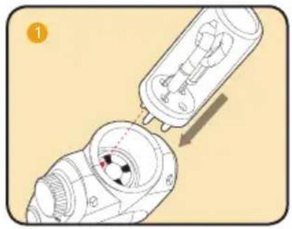
- Using white cotton gloves or a clean cloth, line up the dot on the bottom of the flashtube with the one inside the flashtube socket to ensure correct polarity.
- With the polarity aligned, insert the flash tube into the flashtube socket on the flash unit using firm, even pressure until secure.
natural_image
Diagram showing a mechanical component being inserted into a housing, with no visible text or symbols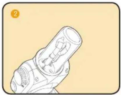
natural_image
Technical line drawing of a mechanical component with no visible text or symbolsREPLACING THE FLASHTUBE
Before removing an old flash tube, ensure the device is switched off and the power source disconnected from the unit. Additionally, remove all accessories connected to the unit's Accessory Mount.
- Using white cotton gloves or a clean cloth, grasp the flashtube using firm, even pressure, and pull the flashtube from the flash unit.
- To install the new bulb, follow the Installing the Flashtube instructions above.
Powering the Flash
The Bolt VB-Series flash units are powered by an external power pack, such as the Bolt PP-400DR, with a high voltage cable via a dedicated port on the side of the flash body. The external power source is sold separately.
Connecting to a power pack:
- Ensure the power pack and flash unit are turned off.
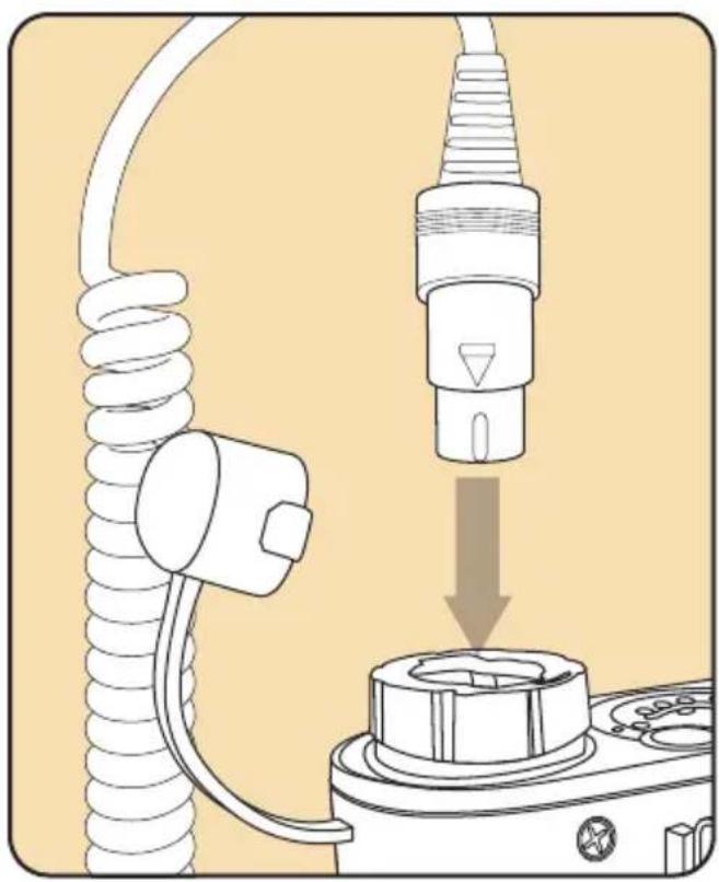
- Insert one end of the high voltage power cable into the output socket of the power pack, and plug the other end into the power socket of the flash.
- Turn on the power pack, and then press the Power button on the flash.
NOTE: Certain power packs, such as the Bolt PP-400DR, will automatically turn the flash on when powered on.
natural_image
Diagram showing a coiled cable being inserted into a plug into a socket (no text or symbols present)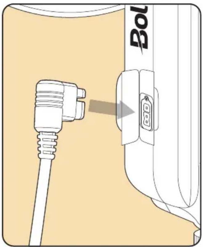
Mounting the Flash
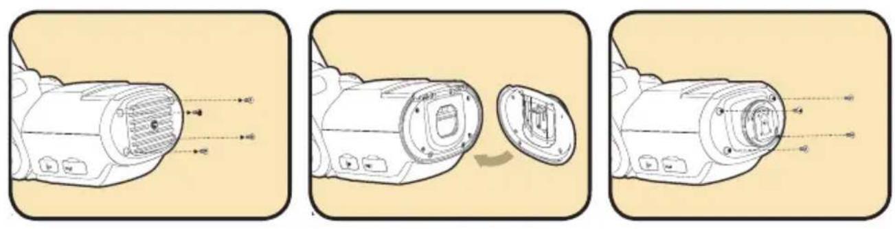
The Bolt VB-Series flash units include interchangeable mounting accessories. The VB-11 has a built-in shoe mount and a separate Stand/Tripod Mount. The VB-22 has two interchangeable shoe and stand mounts, as well as the additional Stand/Tripod Mount. The shoe mount allows the flash to be attached to cameras, brackets, and the like. The stand mount allows the flash to be attached to lightstands, tripods, and anything else with a standard 14 "-20 mounting screw.
To install or remove a VB-22 mounting foot, unscrew the four screws from the base of the flash using a Phillips screwdriver. Carefully install alternate mounting foot and secure by re-installing screws to the unit. If the VB-22's primary usage will be on a lightstand, it is highly recommended to use the built-in stand mounting foot. This will provide a more stable and secure connection than that of the Stand/Tripod Mount.
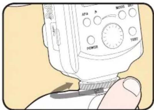
Mounting the Flash on a Shoe or Stand/Tripod Mount
- If using a VB-22, ensure that the Shoe Mounting Foot is securely installed.
- With the unit turned off, loosen the tightening ring on the mount.
- Slide the unit into the shoe.
- Secure the flash by turning the tightening ring clockwise.
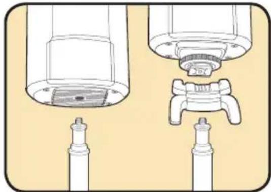
Mounting the Flash on a Stand
- Holding either the Stand/Tripod Mount or the VB-22 with the Stand Mounting Foot securely installed, place the threaded socket over the stand's 14 "-20 installation screw.
- Screw in the Stand/Tripod Mount or VB-22 by turning it clockwise until tight and secure.
- If using the Stand/Tripod Mount, follow the steps above to mount the flash on the foot.
natural_image
Technical line drawing of a mechanical assembly with two views (top and side), no text or symbols present.Setting the Flash Power
The VB-Series flashes incorporate manually-controlled power output that can be varied over 8 stops from 1/1 (full power) to 1/128, and is adjustable in 1/3-stop increments. Turn the Selection Dial clockwise to raise the power level, and counterclockwise lower it.
To avoid overheating and damaging your flash unit, please wait for at least 10 minutes after 75 continuous flashes at full power. The flash will automatically enter thermal protection mode if it gets overheated. The LCD screen will display 🔒 and flash firing will be disabled until the unit has cooled.
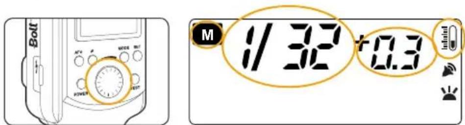
NOTE: Turning the flash power output lower than 1/128 until “OF” is displayed will disable flash firing. This feature is for use with a dedicated remote, such as the Impact ControlSync 16. For more information, see the Dedicated Remote Control section in Triggering the Flash, on the next page.
Triggering the Flash
There are five different ways to trigger the Bolt VB-11 and VB-22 flash units:
- Hot Shoe: The flashes can be triggered by any standard hot shoe, such as a camera, off-camera cord or radio receiver.
- PC Cord: A PC sync socket can be attached to the flash units to trigger the flash. To use this function, open the rubber cover on the PC sync socket and insert a PC cord.
- 3.5 mm Mini Cable: The flash can also be triggered by using a 3.5 mm mini cable flash sync cord. Simply open the rubber covering on the flash's sync jack, insert one end into the jack and the other end into a flash triggering device.
- Optical Slave: Both flashes can be used as wireless slave units in single or multiple flash configurations. To use the slave mode, see the Optical Slave Triggering Modesection of this manual on page 21.
- Dedicated Remote Control: A dedicated remote control, such as the Impact ControlSync 16 Transmitter and Receiver (sold separately), can control triggering, adjust power levels, and turn the AF-Assist and Audio modes on and off. To use the remote, plug the dedicated receiver into the wireless control port on the side of the flash.
AF-Assist Mode
The VB-Series flashes' AF-mode assists the user in focusing the camera in low-light situations. The AF-Assist light on the flash will turn on to illuminate the subject enough for the camera and lens to obtain proper focus.
This mode can be turned on manually pressing the AF button on your flash. The LCD screen will display when the function has been activated. To disable the AF-Assist function and light, push the AF button again.
Audio Function
The Audio function, indicated as 📋 on the LCD screen, is an audible indicator for when the flash unit has fully recycled its charge and is ready to fire. To activate or disable this function, press the Audio button. The icon will appear on the LCD screen when it is activated, and disappear when it's deactivated.
Optical Slave Triggering Mode
Optical slave triggering mode sets your flash to fire wirelessly whenever it detects a signal from a master flash.
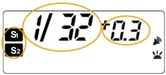
The VB-Series bulb flashes have two slave settings: S1 Mode sets the flash to fire in sync when the master flash is triggered, while S2 Mode allows the flash unit to ignore a single “preflash” from the master and only fire in response to the main flash from the master unit.
To use the optical slave triggering mode, press the Mode button until S1 or S2 is displayed on the LCD screen.
Repeat Mode
Repeat Mode, sometimes referred to as Stroboscopic Mode, causes the unit to fire multiple flashes rapidly. This allows the camera to capture multiple images of a moving subject in a single exposure.
To use Repeat Mode:
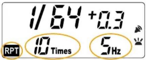
- Press the Mode Selection button until "RPT" is displayed on the LCD screen.
- Press the Set button until the Times indicator flashes, then use the Selection Dial to choose your desired amount.
- Press the Set button again to adjust the flash frequency. Use the Selection dial to find your desired setting.
- Press the Set button again to confirm your settings.
- Set your camera to the appropriate shutter speed.
• Take a test shot to confirm settings.
NOTE: To adjust your camera's shutter speed, divide the Repeat Count number (the number of flashes per frame) by the set frequency of the flash.
For example: if the number of flashes per frame is 10, and the frequency of the flash is 5 Hz, then:
$$ \frac {1 0 \text { flashes per frame }}{5 \mathrm{HZ}} = 2 $$
Therefore, the shutter speed should be 2 seconds.
Different flash power levels allow different amount and frequency combinations. For more information, see Repeat Mode Reference Chart on page 31.
Modifying the Light Output
TILT AND SWIVEL
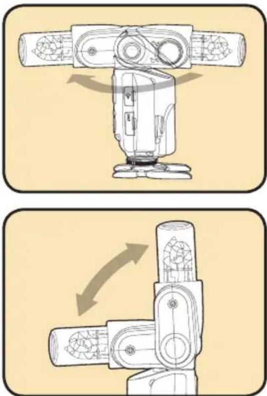
The VB-Series bare-bulb flash heads can tilt down to -15^ , and up at 45^ , 60^ , 75^ , and 90^ angles from lens. They can also sw el horizontally 135^ to the right and 180^ to the left. Using the flash to directly illuminate a subject often creates harsh, unnatural, and unattractive shadows. To avoid this, the flash can be tilted or swiveled, enabling you to aim your flash at a large white or neutral-colored surface such as a ceiling, wall, or reflector. The light will bounce off the larger surface before striking your subject, providing softer, more natural illumination. In addition, the flash can tilt down by 15 degrees in order to fully illuminate your subject when shooting close-up photography.
To adjust the tilt and swivel of the flash head, press and hold the Position Release button. Release the button to lock it in the current position.
When bouncing your flash, you may need to adjust your exposure settings, since there will be less light falling on your subject. The farther away the bounce surface and your subject are, the less illumination there will be.
TIP: Bouncing your flash off colored surfaces can create a color cast in your images. Bouncing off a white or neutral-colored surface will not alter the color of the light, while bouncing off a gold-toned surface can give portraits a warmer look. Other colors, while usually not desirable, can be used for creative effects.
Lighting Effects
To manipulate the quality of light from your bare-bulb flash, accessories are available. Included with the Bolt VB-Series flashes are a reflector and diffuser.
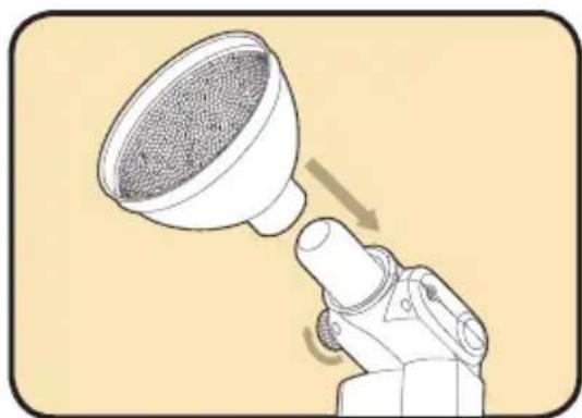
The reflector is used to amplify and widen the reach of the flash's light. Using this by itself is useful in lighting a large wall or space with one light source. The included diffuser will soften the light, creating more attractive and uniform lighting on a subject or area.
Other accessories, such as snoot sets (used for focusing light), beauty dishes (used for lighting portraits), softboxes (a larger diffuser), and an umbrella mounting kit (for quick and easy broad, wrap-around lighting) are also useful tools for properly lighting your scenes.
USING THE REFLECTOR AND DIFFUSER
- Rotate the Accessory Locking Ring in a counterclockwise direction until loose.
- Slide the reflector into the Accessory Mount.
- Rotate the Accessory Locking ring clockwise until tight.
- If desired, snap the diffuser and retaining ring onto the front of the reflector.
NOTE: Other dedicated accessories, such as snoots, beauty dishes, and grids, can be mounted similarly. For a list of recommended accessories, see page 32 in this manual.
natural_image
Illustration of a hand holding a funnel-shaped object with a mesh grille, no text or symbols present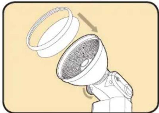
natural_image
Illustration of a speaker emitting sound waves into a lens, showing the lens and speaker blades (no text or symbols)Troubleshooting
| Problem Solution | ||
| The flash is stuck in a hot shoe. • | Turn the hot shoe mount locking ring counterclockwise until loose. | |
| The flash is turned on but won’t fire. | Check that the flash is connected to a power source, the power source is turned on, and the cables properly connected.(Page 14)If connected via hot shoe, make sure the pin at the bottom, as well as the hot shoe, are clean and free of debris.If the flash has overheated, it will need 10 to 15 minutes to cool down before being able to fire again. (Page 18)The power setting is set to “OF”. (Page 18) | |
| The flash isn’t being triggered in slave mode, or the flash is not noticeable in the picture. | ·Ensure the master flash is within transmission range (approximately 33’/10 m) and that the wireless sensor has a clear line of sight with the master flash.·The ambient light may be too high.·Make sure that the flash is set to the appropriate slave mode. (Page 21) | |
| The bottom of the image looks dark. | ·To fully illuminate your subject when shooting close-up photography, tilt the flash down to the -15° position. (Page 24) | |
| There’s a whining sound coming from the flash. | ·This is normal and does not indicate a malfunction. When the flash heats up from continuous use, vibrations inside the unit may cause this sound. It will dissipate as the unit cools. | |
| Specifications VB-11 VB-22 | ||
| Dimensions | 8.07" x 3.54" x 2.75" (205 x 90 x 70 mm) 7.87" x 3.66" x 2.95" (200 x 93 x 75 mm) | |
| Weight | 1.5 lb. (0.68 kg) 2.1lb. (0.95 kg) | |
| Head Rotation | 315° (135° right, 180° left) 315° (135° right, 180° left) | |
| Head Tilt | 90° to -15° 90° to -15° | |
| Power Output | 180 W/s 360 W/s | |
| Guide number | 196' (60 m) 262' (80 m) | |
| Flash coverage | 28 mm (with reflector) 28 mm (with reflector) | |
| Flash duration | 1/300 – 1/10,000 second | 1/300 – 1/10,000 second |
| Recycle time | 0.05-2.6 seconds w/ Bolt PP-400DR 0.1 | 5.2 seconds w/ Bolt PP-400DR |
| Manual mode power output | 1/1, 1/2, 1/4, 1/8, 1/16, 1/32, 1/64, 1/128 | 1/1, 1/2, 1/4, 1/8, 1/16, 1/32, 1/64, 1/128 |
| Slaves timing modes | Instant Sync (S1), Skip Pre-Flash (S2) | Instant Sync (S1), Skip Pre-Flash (S2) |
| Slave sensor range | Approximately 33' (10 m) | Approximately 33' (10 m) |
| Power source | External power pack | External power pack |
Repeat Mode Reference Chart
| Frequency | Flash Output Level | ||||||
| 1/1, 1/2 1/4 | 1/8 1/16 1/32 | 1/64 1/128 | |||||
| 1 1 30 50 70 80 99 | 99 | ||||||
| 2 1 2 4 70 80 99 99 | |||||||
| 3 1 2 2 7 80 99 99 | |||||||
| 4 1 2 2 4 16 99 99 | |||||||
| 5 1 2 2 3 8 99 99 | |||||||
| 6 1 2 2 3 6 99 99 | |||||||
| 7 1 1 2 3 5 25 99 | |||||||
| 8 1 1 2 2 5 15 99 | |||||||
| 9 1 1 2 2 4 10 99 | |||||||
| 10-11 1 1 2 2 4 | 6 | 99 | |||||
| 12-13 1 1 2 2 3 | 6 | 99 | |||||
| 13-15 1 1 2 2 3 | 5 | 99 | |||||
| 15-19 1 1 2 2 3 | 5 | 36 | |||||
| 20-99 1 1 2 2 3 | 5 | 20 | |||||
Recommended Accessories
The Bolt VB-Series Bare-Bulb flashes have a wide range of accessories available for purchase, including power units, special effects kits, and various other light modifiers.
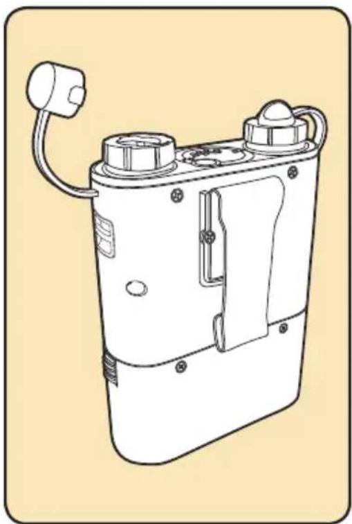
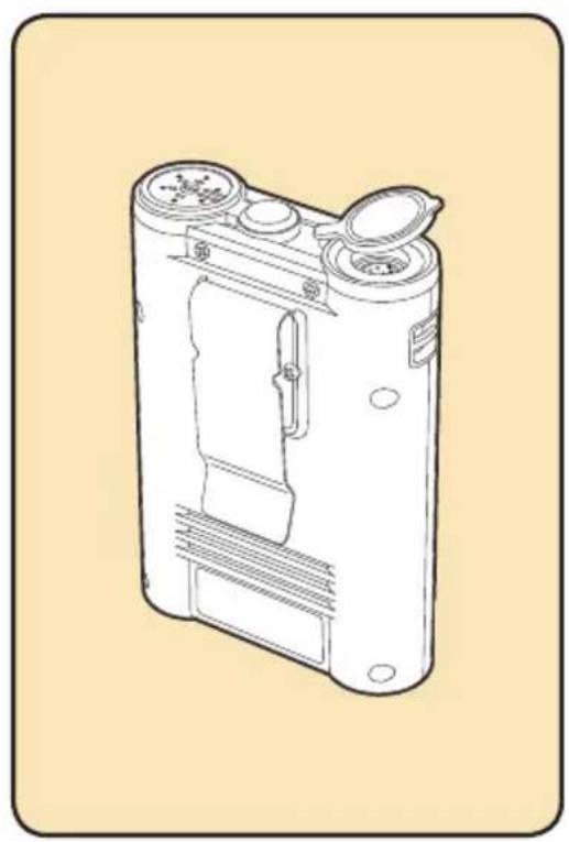
The Bolt VB-Series bare-bulb flashes use external power packs to power the units. Bolt offers the PP-400DR and PP-310 Power Packs, which have a blazing fast 1-second recycle time. Additionally, the 2 sockets on the PP-400DR provide the user with the ability to power two flashes simultaneously. The PP-400DR has enough power for 1400 full-power flash bursts, while the PP-310 provides 500 full-power flash bursts.
natural_image
Line drawing of a mechanical device with two ports and a cable (no text or symbols)PP-400DR Dual Outlet Power Pack
natural_image
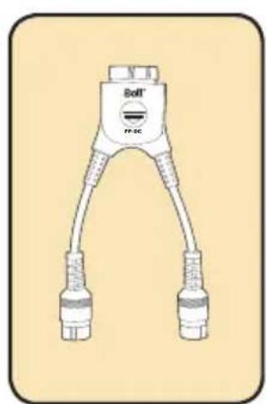
Line drawing of a portable electronic device with ventilation slots and a handle (no text or symbols)The PP-DC Doubler Cable allows you to plug one HV power cord into two power pack outlets, cutting recycle time in half and aiding in avoiding missed shot opportunities. The PP-SC Splitter Cable allows you to power two flashes from one power pack socket.
natural_image
Illustration of a medical or laboratory device with two connectors and a labeled connector (no text or symbols on the device itself)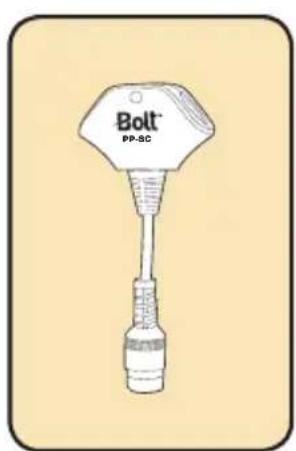
PP-DC Doubler Cable PP-SC Splitter CablePP-310 Compact Power P
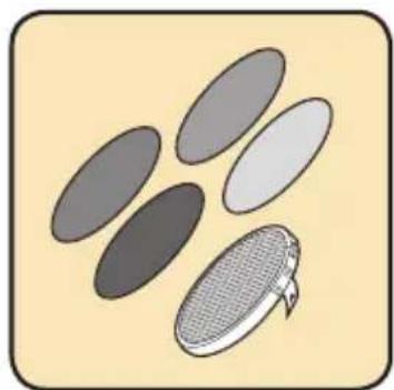
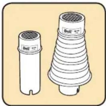
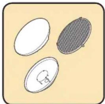
An array of light customization kits is available for use with the Bolt VB-Series bare-bulb flashes. The Grid and Filter Kit helps the user to stylize and focus mood and accent lighting with the four included color filters and honeycomb grid. The cone and tube Snoot Set is used to create dramatic lighting effects by focusing the light into tight circles. The Beauty Dish and Grid Kit is ideal for creating a soft, yet crisp, quality of light or increasing contrast and directionality. Additionally, the Umbrella Mounting Kithelps facilitate the setup and installation of an umbrella for enhanced lighting effects.
natural_image
Illustration of a filter or grating device with five oval-shaped filters and one meshed cover (no text or symbols)VB-GFK Grid and Filter Kit
natural_image
Illustration of two cylindrical industrial components with ventilation grilles, one upright and one conical (no text or symbols)VB-SS Snoot Set
natural_image
Three oval-shaped objects with different internal patterns, one filled with a mesh grille and the other with a small circular feature (no text or symbols)VB-BDK Beauty Dish and Grid Kit
natural_image
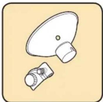
Simple line drawing of a speaker and microphone components (no text or symbols)VB-UMK Umbrella Mounting Kit
natural_image
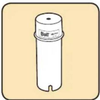
Simple line drawing of a cylindrical object with a labeled 'Bolt' and a notch, no text or symbols present.VB-FTC Flashtube Cover
natural_image
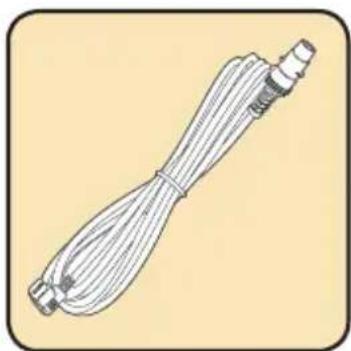
Illustration of a coiled cable or hose with connectors (no text or symbols)VB-PC-S 15' Extension Power Cord
natural_image
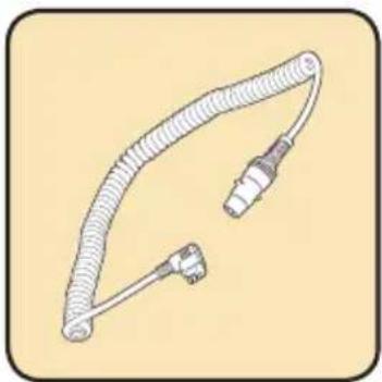
Illustration of a coiled medical or electrical device with connectors (no text or symbols)VB-PC-C Coiled Power Cord
natural_image
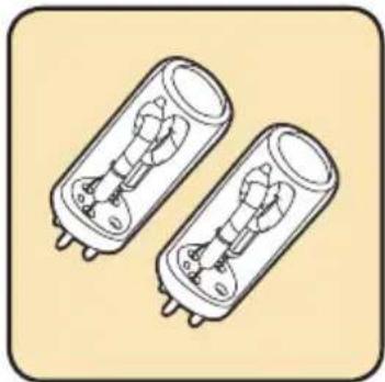
Illustration of two cylindrical electronic components with internal circuitry (no text or symbols)VB-11-FT and VB-22-FT Flashtubes
In addition to light modifiers, the VB-series flashes also have multiple complementary and replacements accessories available. The Flashtube Cover protects your flash's flashtube, allowing you to keep it mounted to the flash during transit. The 15'
Extension Power Cord provides you with more reach, offering the ability to power your flash unit from an increased distance. Additionally, replacement power cords and flashtubes are also available.
One-Year Limited Warranty
This BOLT product is warranted to the original purchaser to be free from defects in materials and workmanship under normal consumer use for a period of one (1) year from the original purchase date or thirty (30) days after replacement, whichever occurs later. The warranty provider's responsibility with respect to this limited warranty shall be limited solely to repair or replacement, at the provider's discretion, of any product that fails during normal use of this product in its intended manner and in its intended environment. Inoperability of the product or part(s) shall be determined by the warranty provider. If the product has been discontinued, the warranty provider reserves the right to replace it with a model of equivalent quality and function.
This warranty does not cover damage or defect caused by misuse, neglect, accident, alteration, abuse, improper installation or maintenance. EXCEPT AS PROVIDED HEREIN, THE WARRANTY PROVIDER MAKES NEITHER ANY EXPRESS WARRANTIES NOR ANY IMPLIED WARRANTIES, INCLUDING BUT NOT LIMITED TO ANY IMPLIED WARRANTY OF MERCHANTABILITY OR FITNESS FOR A PARTICULAR PURPOSE. This warranty provides you with specific legal rights, and you may also have additional rights that vary from state to state.
To obtain warranty coverage, contact the BOLT Customer Service Department to obtain a return merchandise authorization ("RMA") number, and return the defective product to BOLT along with the RMA number and proof of purchase. Shipment of the defective product is at the purchaser's own risk and expense. For more information or to arrange service, visit www.boltflashes.com or call Customer Service at 212-594-2353.
Product warranty provided by the Gradus Group.
www.gradusgroup.com
BOLT is a registered trademark of the Gradus Group.
© 2016 Gradus Group LLC. All Rights Reserved.

BOLT™ A Gradus Group Brand
- Introduction
- Contents
- Overview
- Additional VB-22 Parts:
- LCD:
- Included Accessories:
- Warnings
- Using the Flash
- INSTALLING THE FLASHTUBE
- REPLACING THE FLASHTUBE
- Powering the Flash
- Connecting to a power pack:
- Mounting the Flash
- Setting the Flash Power
- Triggering the Flash
- There are five different ways to trigger the Bolt VB-11 and VB-22 flash units:
- AF-Assist Mode
- Audio Function
- Optical Slave Triggering Mode
- Repeat Mode
- To use Repeat Mode:
- Modifying the Light Output
- TILT AND SWIVEL
- Lighting Effects
- USING THE REFLECTOR AND DIFFUSER
- Troubleshooting
- Recommended Accessories
- One-Year Limited Warranty
Brand : Bolt
Model : VB-11
Category : Flash Drive