
AE-510-I - Security Camera Vivotek - Free user manual and instructions
Find the device manual for free AE-510-I Vivotek in PDF.


| Product Type | Security Camera |
| Model | AE-510-I |
| Brand | Vivotek |
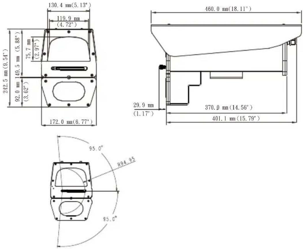
| Dimensions (with IR & Wiper) | 460 (L) x 172 (W) x 242.5 (H) mm |
| Net Weight | 8 kg |
| Power Input | 24V AC |
| Power Consumption | Window heater: 5W, Fan: 2W, IR LED: 12W, Wiper: 6W |
| Protection Level | IP68, IK10 (IP66 with wiper) |
| Construction Material | AISI 316L stainless steel |
| Operating Temperature | -20°C to +50°C |
| IR Illuminator | 850nm, 50m@40°, 140m@10° |
| IR Control | Light sensor, RS485 command, or camera digital output |
| Wiper | Yes, with washer control via DI or RS485 |
| Window Heater Control | On below 20°C, Off above 30°C |
| Blower Control | On above 35°C, Off below 25°C |
| Cable Glands | PG16 x 2 |
| Mounting Options | Wall mount, pole mount, corner mount |
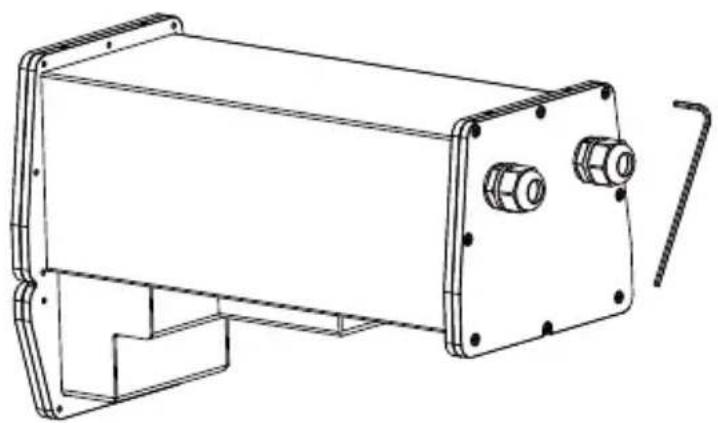
| Included Accessories | Quick Installation Guide, allen wrench |
| RS485 Protocol | Pelco D, baud rate 2400, 8 data bits, no parity, 1 stop bit |
| Customizable RS485 Commands | Yes, for IR mode, wiper, and lens control |
Frequently Asked Questions - AE-510-I Vivotek
User questions about AE-510-I Vivotek
0 question about this device. Answer the ones you know or ask your own.
Ask a new question about this device
Download the instructions for your Security Camera in PDF format for free! Find your manual AE-510-I - Vivotek and take your electronic device back in hand. On this page are published all the documents necessary for the use of your device. AE-510-I by Vivotek.
USER MANUAL AE-510-I Vivotek
Stainless Steel Housing Series
Quick Installation Guide
natural_image
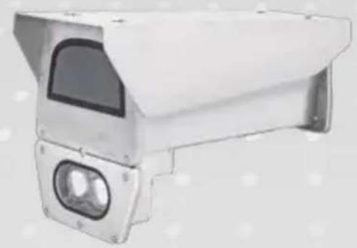
Exterior view of a white surveillance camera with dual lenses (no text or symbols visible)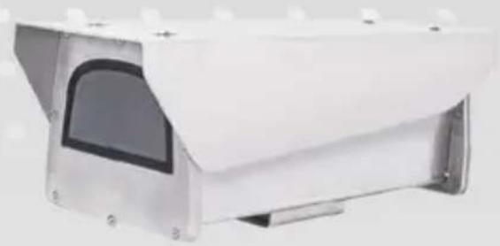
natural_image
Exterior view of a white surveillance camera with mounted lenses and mounting brackets (no visible text or symbols)Rev. 1.0
UNPACKING:
Unpack carefully. Electronic components can be damaged if improperly handled or dropped. If an item appears damaged in shipment, place it properly in its carton and notify the shipper.

IMPORTANT!:
- Read and follow Instructions: All operating and user instructions should be read and followed before the unit is to be operated.
- Electrical Connections: Only a qualified electrician is allowed to make electrical connections.

Specifications
| Model Number AE-510 AE-510-I | ||
| Power Input 24V AC 24V AC | ||
| Power Output 12VDC, 24VAC 12VDC, 24VAC | ||
| Power Consumption Window heater: 5W;Fan: 2W; | Window heater: 5W;Fan: 2W;IR LED: 12W;Wiper: 6W | |
| VAIR Illuminator N/A 850nm | 50m@40°, 140m@10° | |
| EnvironmentalOperation Temp. | -20°C ~ +65°C -20°C ~ +50°C | |
| Window heater ON/OFF < 30°C (86°F) ON>30°C (86°F) OFF | ≤ 20°C (68°F) ON≥ 30°C (86°F) OFF | |
| Blower Control >30°C (86°F) ON< 30°C (86°F) OFF | ≥35°C (95°F) ON≤ 25°C (77°F) OFF | |
| Protection Level IP68, IK10 IP68, IK10 (IP66 w/ wiper) | ||
| Construction AISI 316L stainless steel AISI 316L stainless steel | ||
| Dimensions | 460 (L) x 172 (W) x 163.5(H) mm | 460 (L) x 172 (W) x 242.5(H) mm |
| Net Weight | 7.5kg | 8kg |
| Cable Grants PG16 x 2 | PG16 x 2 | |
If you plan to install this camera housing into a tropical, sea coastal, or an environment where salt water or corrosive industrial waste water/moist are present, please seal each stainless steel screws and fittings with a silicon grease compounds. This will help prevent electrolysis to occur and extend the life span of the camera and housing.

IMPORTANT:
- Disconnect devices: A readily accessible disconnect device in the building installation wiring should be incorporated.
- Electrical Connection: Only a qualified electrician is allowed to make electrical connections.
II Mounting Configuration & Dimensions
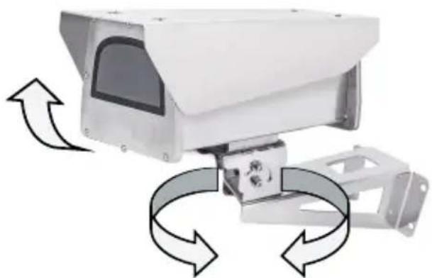
Swivel Positions and Directions
natural_image
Exterior view of a surveillance camera with directional arrows indicating rotation (no text or symbols)Dimensions
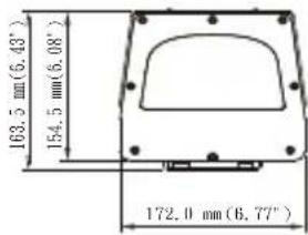
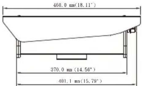
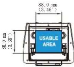
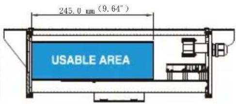
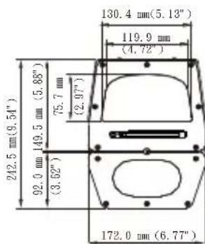
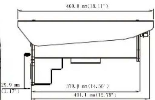
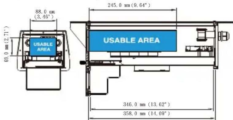
Dimensions with the IR unit and wiper
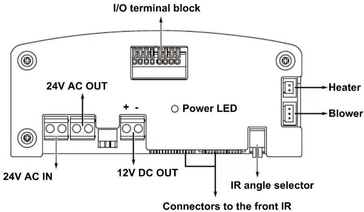
III Component Description
AE-510
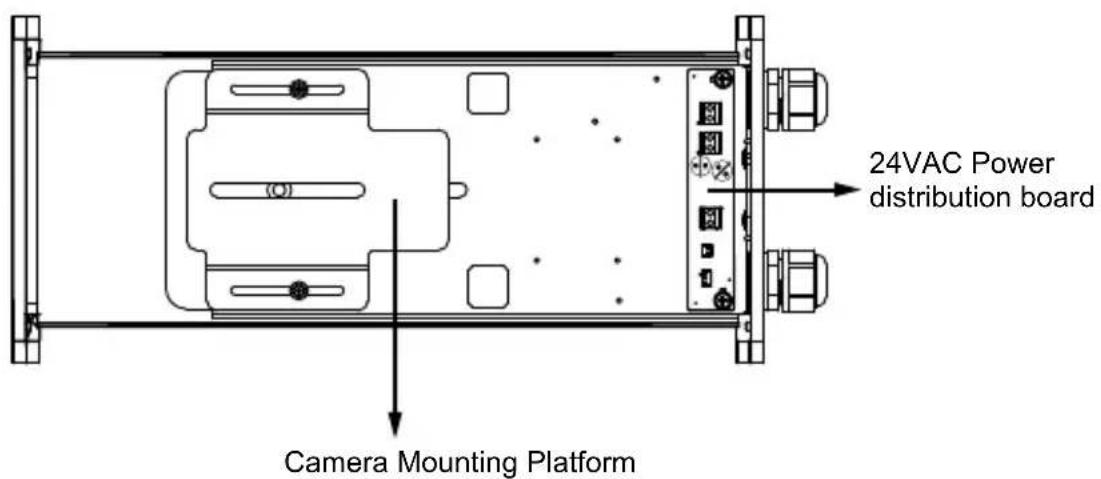
AE-510-I
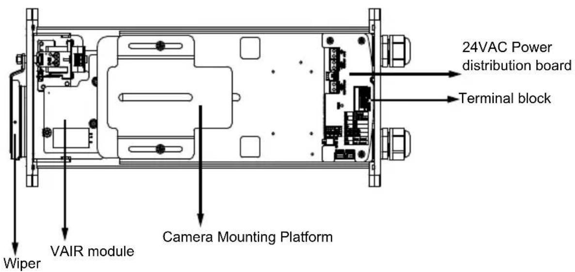

Installation Suggestions

WARNING:
- When install a housing with an IR illuminator:
Please avoid eye exposure or apply appropriate protection, such as wearing a pair of Infrared protection glasses, when working with the product. Always use camera live view to observe IR lighting effects.
Installation
- How to open the housing
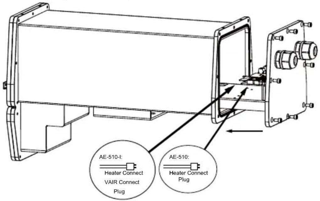
Unscrew the bolts on the rear flange, using the allen wrench supplied.
natural_image
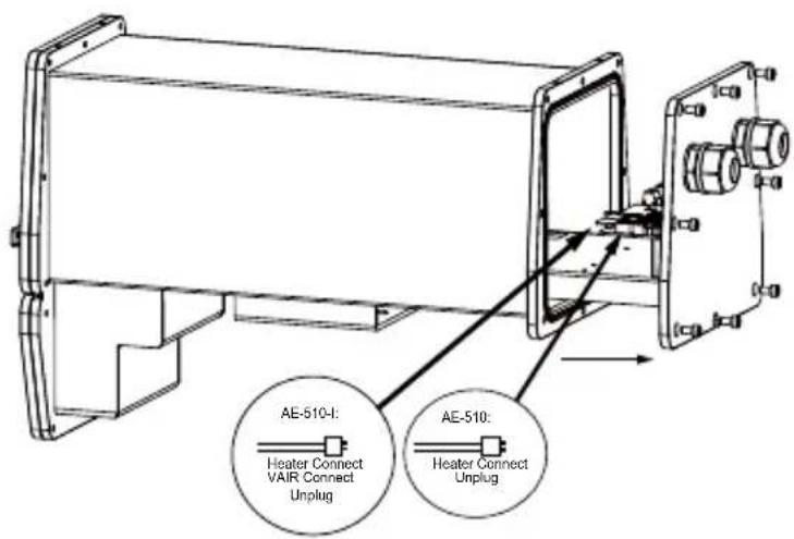
Technical line drawing of a rectangular electronic device with mounting flanges and a side bracket (no text or symbols)Slide out the rear cover plate of the housing, taking care to leave the sealing washer in its seating. Heater or wiper or VAIR connect need unplug.
- Prepare power wires, a ground wire, and a CAT5e Ethernet cable. Pass them through the PG16 waterproof connectors and its waterproof components.
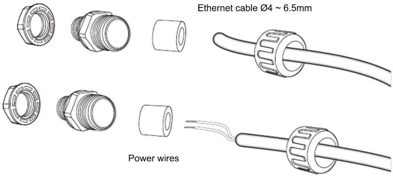
Note that some cables are connected when shipped. You do not need to connect heater, blower, and the front IR powere wires.

IMPORTANT:
- Recommend to cover the ethernet or power cable with stainless steel tube in order to prevent the corrosion of cable.
You may need to remove the RJ45 connector, and use a crimping tool to connect the Ethernet wires to an RJ45 connector inside the enclosure. Use an Ethernet cable of the width of 5 \~ 6.5mm.
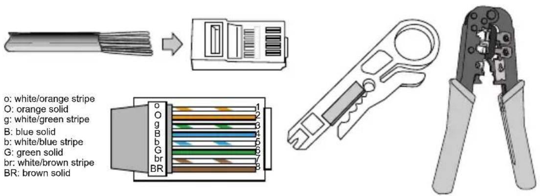
-
When done, tighten up and install the waterproof connectors.
-
Assemble the camera components, e.g., the CS ring and lens module. Secure the mounting plate to the bottom of the camera (the label side) using the included screw.
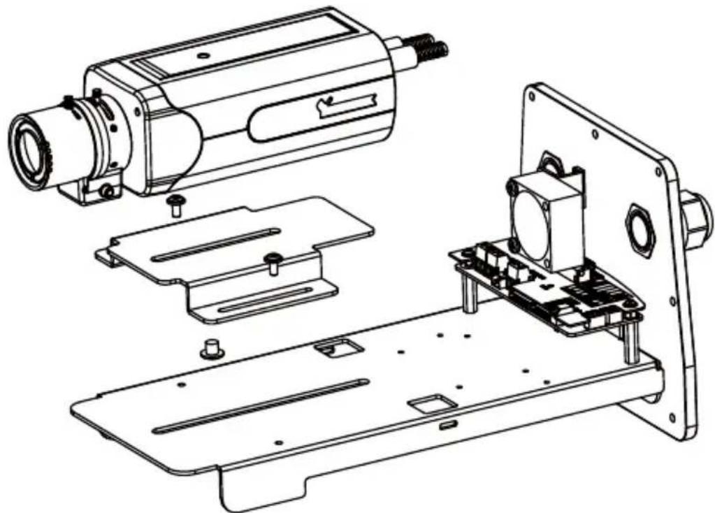
natural_image
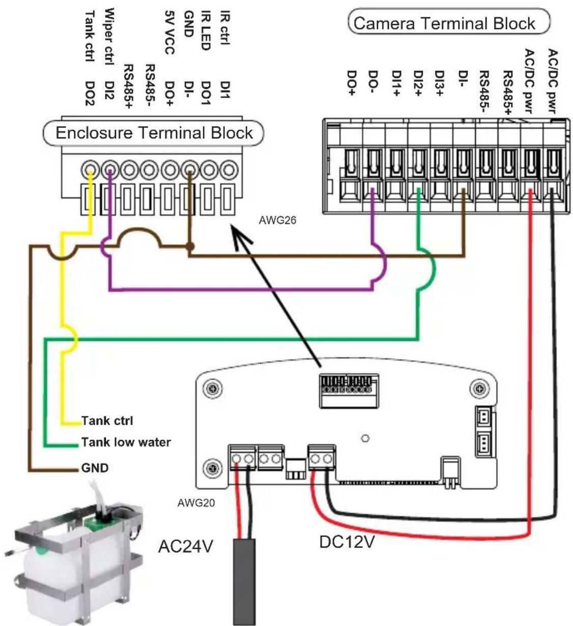
Technical line drawing of an industrial machine assembly (no text or symbols present)- Connect 24V power source to the power input terminal. Connect power wires from the DC 12V output to the camera.
Below is the distribution board drawing power from 24V AC.
AE-510
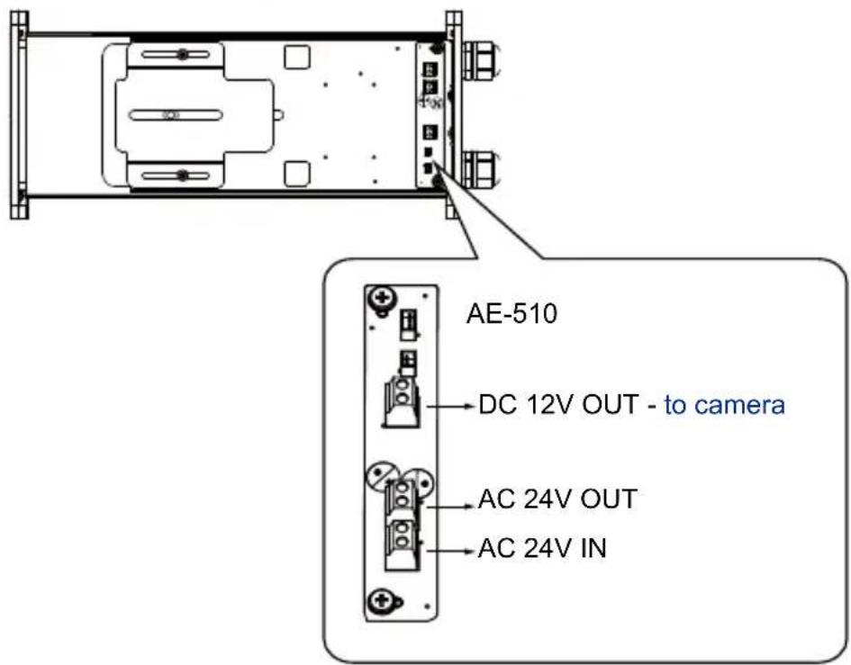
Below is the pinouts for the DI/DO terminal block:
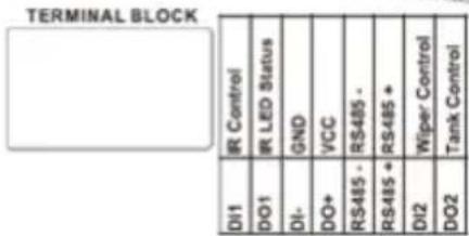
Facing the rear side of the housing, from left to right:
| DO2 Connect to tank water pump. | |
| DI2 Wiper control, connects to IP camera's DO for manually triggering washer. | |
| RS485+ RS485+, RS485 can be used to control IR illuminator beam angles, etc. | |
| RS485- RS485- | |
| DO+ +5V VCC | |
| DI- GND | |
| DO1 IR LED status | |
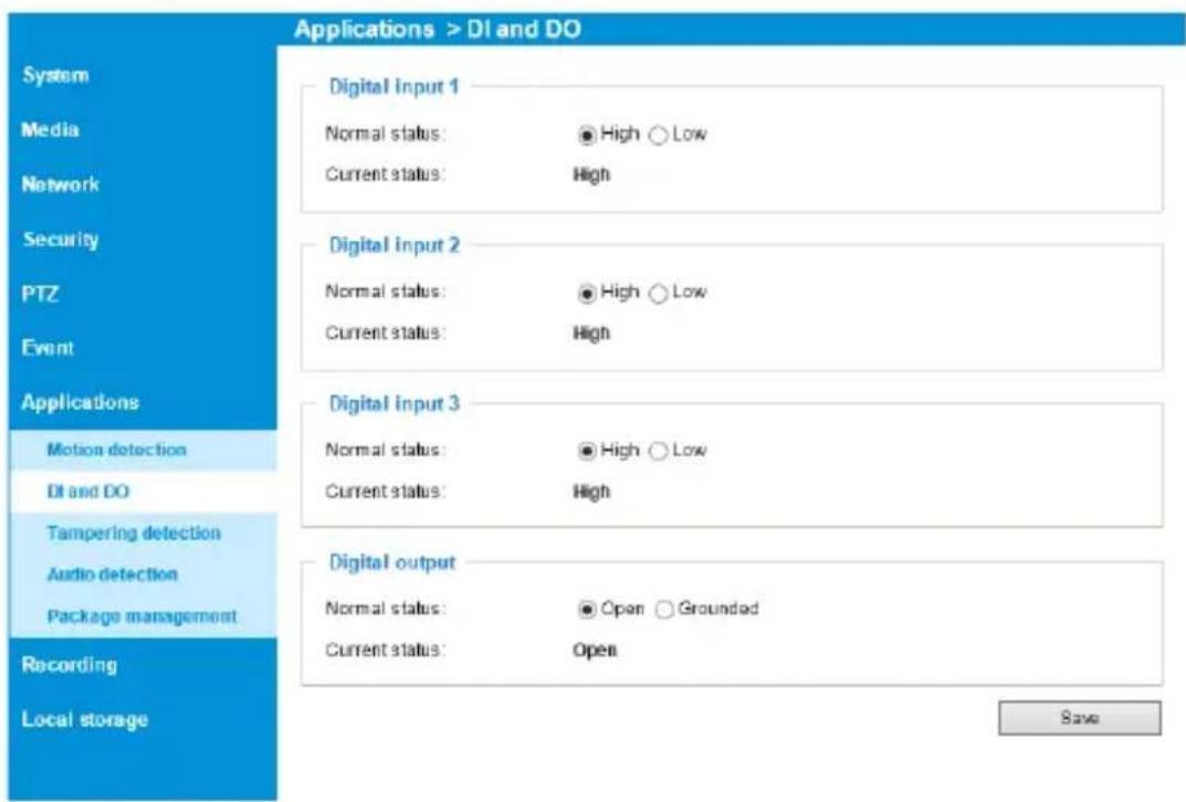
| DI1 IR control, synchronizes day/night mode switching for IP camera. It is related to IR cut filter. | |
Configuring IR illuminator
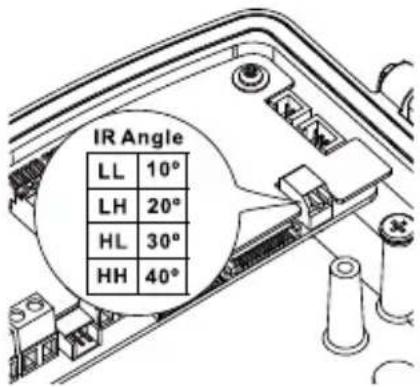
DIP Switch :
LL
LH
HL
HH
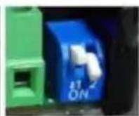
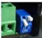
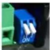
Below are the parameters of the IR illuminator. Use the onboard jumpers to configure the beam angle for different effective illumination range.
| VAIR 12W 6W | ||||||||
| no. of LEDs | 2P 2P | |||||||
| Beam angle | 10^ | 20^ | 30^ | 40^ | 10^ | 20^ | 30^ | 40^ |
| Distance (meter) | 140m 1 | 10m 80 | m 50m | 100m 80 | 0m 60m | 40m | ||
-
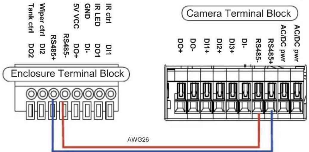
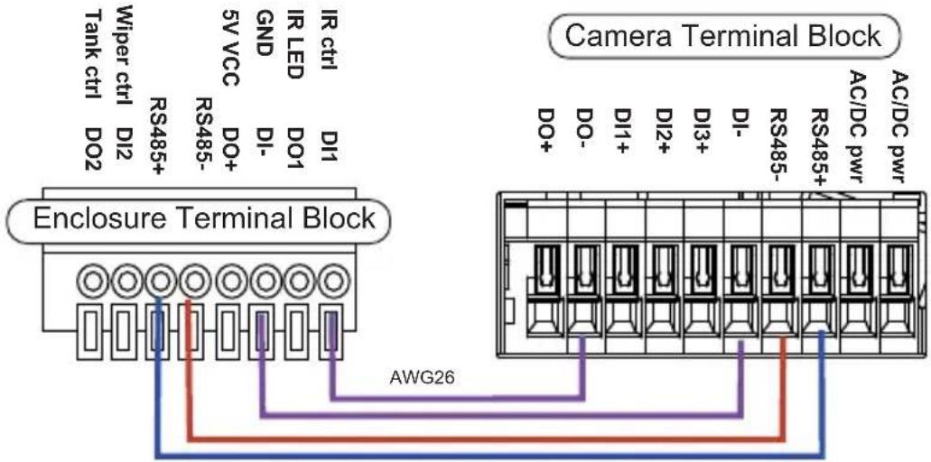
Connection for IR control by IR light sensor, RS485 and camera digital output (AE-510-I)
-
IR control by IR Light sensor
The below connection enables the synchronization of IR light sensor and auto day/night switch on the camera
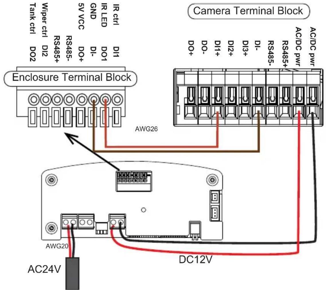
- IR control by RS485 command
Allow user to configure the RS485 command via camera web UI to cotrol IR on/of _f .
Note the wire gauge requirements for making the power connections. (24VAC 24W load)
| Wire Gauge 22 20 18 16 14 12 | ||||
| Distance 55 90 150 230 270 600 feet |
3. IR control by Camera DO
Camera will automatically trigger IR light on/off via DO.
Below is a diagram for water tank and wiper control. The wiper can be started by manually triggering the Digital Output from the camera user interface.
- Before closing the housing reinsert the bottom orientating the slide according to the installation required, on the wall bracket or on the Pan & tilt head, for the right camera fitting. Pay attention not to damage the gasket. Make sure that the sealing ring is correctly fitted in its position.
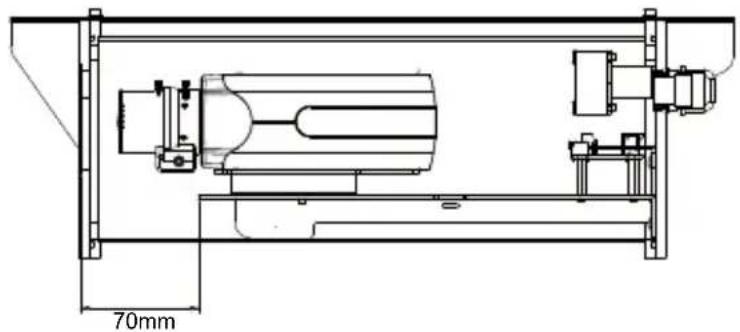
The front end of the slider is about 70mm from the window. Please install the camera in the appropriate position.
natural_image
Technical line drawing of a mechanical assembly with dimension标注 (70mm), showing internal components and mounting brackets (no text or symbols beyond measurement label)Before closing the housing, be sure to have rightly fitted the internal slide according to the type of installation & plug heater or wiper or VAIR connector to power board.
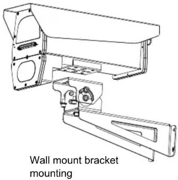
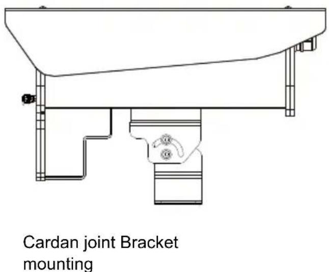
Install wall mount bracket or Cardan joint bracket.
8. Sunshield mounting:
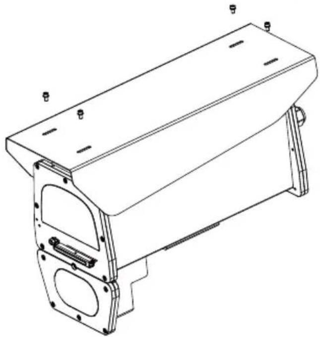
Position the sunshield on the housing and fix it flanges of the housing with the equipped screws.
natural_image
Technical line drawing of a mechanical housing component with mounting flanges and mounting holes (no text or symbols)9. The housing can also be installed using the pole-mount or corner-mount.
The mounting hole definition is illustrated below.
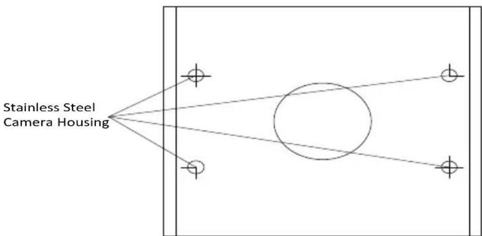
Pole Mount
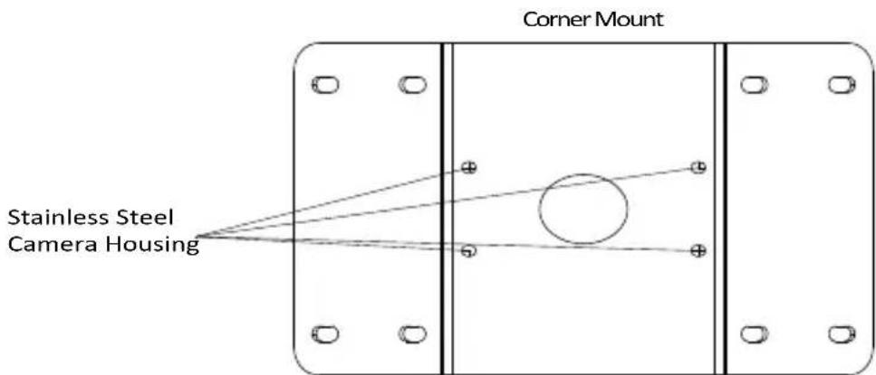
10. Firmware configurable options:
Open a web console with the camera.
Use the Media > Focus function to tune for a best image focus on your target area.
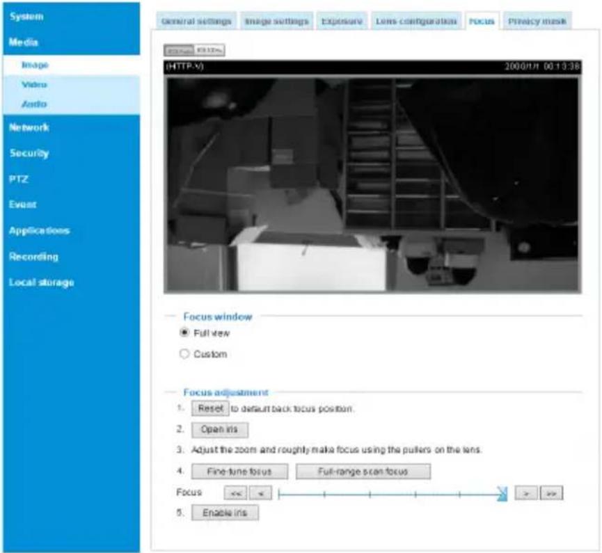
If preferred, e.g., shooting fast moving vehicles, select the 60fps frame rate.
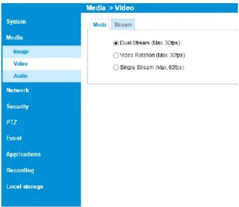
Make sure that external IR is turned on in the night mode, and that the IR cut filter option is synchronized with the digital input you connected.
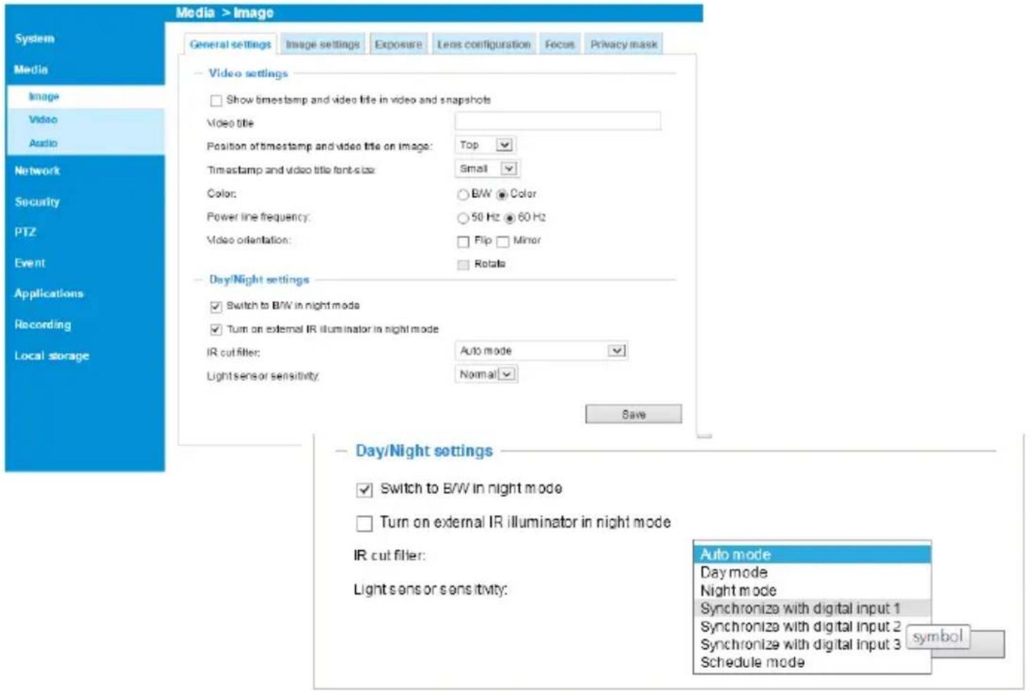
In the night mode, check if the input signals are correctly detected. You may simulate the night mode by blocking the IR unit's light sensor. Change the triggering parameters when necessary.
For housings that come with IR illuminators, wiper, and washer, commands can be delivered via the RS485 protocol. The RS485 connection uses the Pelco D protocol.
Configuration parameters:
| Baud rate 2400 | |
| Data bits 8 | |
| Parity None | |
| Stop bit 1 | |
Command format:
| Byte1 Byte2 | Byte3 Byte4 | Byte5 Byte6 | Byte7 | |||
| Sync Addr CMND1 | CMND2 | DATA1 | DATA2 | CKSM |
Addr range: 0x00 \~ 0xFE. CKSM: check sum is the last 8 bits of the sum of Byte2 through Byte6.
Command Group 1:
| Command Description | Command (hexadecimal, "ox" is omitted) | Note |
| ValR Lens Stop FF 01 00 00 00 00 | 01 Pelco D - Zoom Stop | |
| VAIR Lens Wide FF 01 00 40 00 00 | 0 41 Pelco D - Zoom Wide | |
| ValR Lens Tele | FF 01 00 20 00 00 21 Pelco D - Zoom Tele | |
| Wiper On | FF 01 00 09 00 01 0B | Pelco D – Aux 1 On |
| Wiper Off | FF 01 00 0B 00 01 0D | Pelco D – Aux 1 Off |
| Wiper and Washer On | FF 01 00 09 00 02 0C | Pelco D – Aux 2 On |
| Wiper and Washer Off | FF 01 00 0B 00 02 0E | Pelco D – Aux 2 Off |
| IR Led Force On | FF 01 00 09 00 03 0D | Pelco D – Aux 3 On |
| IR Led Force Off | FF 01 00 0B 00 03 0F | Pelco D – Aux 3 Off |
Command Group 2:
| Command Name | Command (hexadecimal, ox is omitted) | Note |
| Addr configuration | FF 01 00 18 01 dd CKSM | dd: 0x00 ~ 0xFE; for example, when addr is 2, the command looks like FF 01 00 18 01 02 1C |
| IRMode | FF 01 00 18 02 mm CKSM | mm: IR modemm=0x02: Light Sensor Auto (Default)mm=0x03: DI Triggermm=0x04: via RS485 Command(When receiving IR Led Force On / IR Led Force Off command, will switch to using the IR Mode -RS485 Command)For example,IRmode_AutoFF 01 00 18 02 02 1DIRmode_DIFF 01 00 18 02 03 1EIRmode_CMDFF 01 00 18 02 04 1F |
| LightSensorGate FF 01 00 | 18 03 LL CKSM When the IR Mode | Light Sensor Auto,the Lux value to turn IR LED can be configured.LL: Lux, changes is made by every10LuxFor example:LightSensorGate = 100FF 01 00 18 03 0A 26LightSensorGate = 200FF 01 00 18 03 14 30 |
The parameters of IR illuminator can be controlled via the RS485 connection. You can enable the connection in Configuration > PTZ > Mechanical window. Select the defaults for the IR illuminator: Pelco D, baud rate - 2400, Data bits - 8, Stop bit - 1, Parity - none.
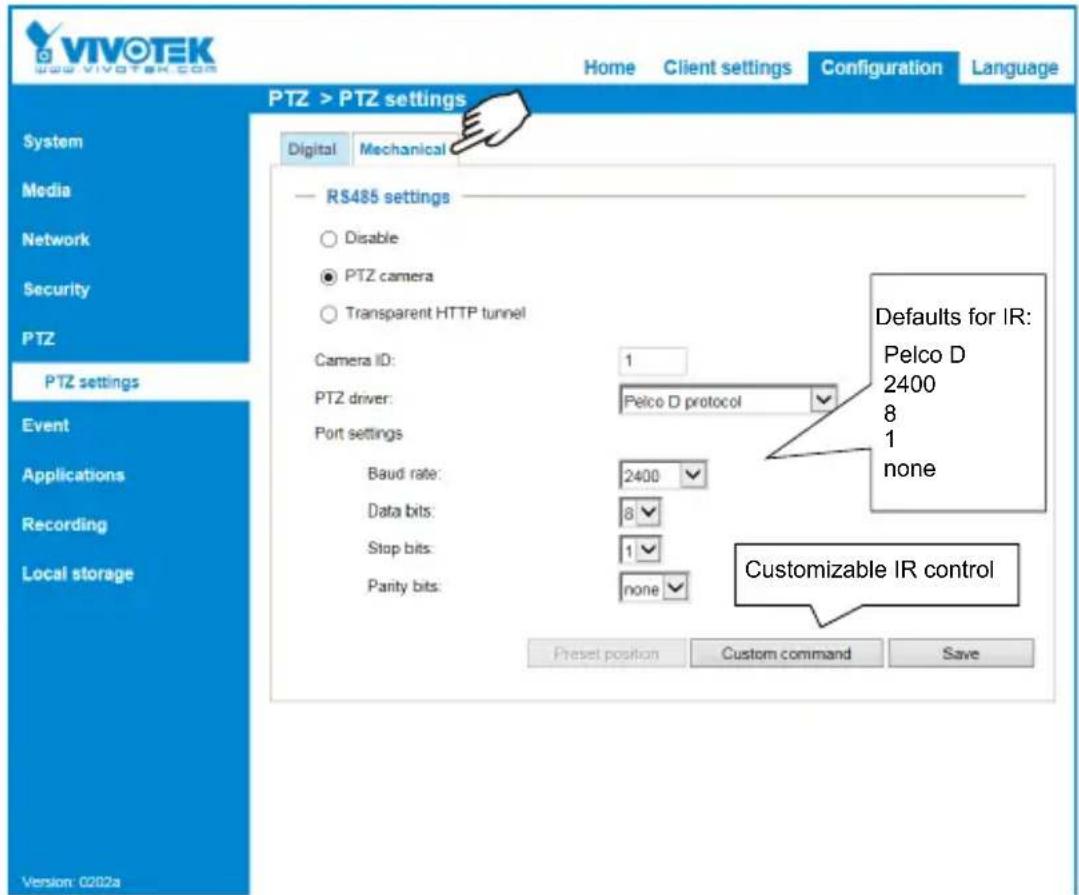
You can create custom command buttons by entering the Button name and the command itself:
>Custom command
Custom command
Leaving the "Button name" field empty means the command button will not be displayed in the homepage.
Button name
Command 1:
TH10%
Command 2:
TH20%
Command 3:
TH50%
Command 4:
DIMMING100%
Command 5:
DIMMING60%
Command
FF012101B00003D6
FF012101B00005D8
FF012101B00007DA
FF012101BF0009EB
FF012101B00007DA
Save
Close
ValR: The VAIR control include those on the IR Led and ValR Lens.
There are 3 IR mode commands
IRMode = Light Sensor Auto (Default)
sensor lux reading < LightSensorGate - LED On
sensor lux reading >= (LightSensorGate + 10 Lux) - LED Off
IRMode = DI_1 Trigger (IR triggered on by DI
DI_1 shorted DI-(Low) - LED On
DI_1 open (High) - LED Off
IRMode = controlled by RS485 Command (Pelco D - Aux 3 On/Off)
IR Led Force On - LED On
IR Led Force Off - LED Off
DO 1 as IR Status Feedback
LED On, DO_1 is grounded via MOSFET (DI- connected)
LED Off, DO_1 no input
ValR Lens Zoom control
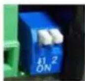
Dip Switch
4 configurations using the Dip Switch on the distribution board.
When Lens stops, its last position will be memoried, and when powered on again, lens will move to the previous position. When powered on for the first time, Lens will follow the DIP switch configuration.
Wiper & Wahser control)
DI_2 Trigger:
When DI_2 connected to DI- (Low), wiper and washer operate for 3 times and then stop.
Using RS485 Command –Wiper Only (Pelco D – Aux 1 On/Off)
Wiper On, wiper takes action
Wiper Off, wiper starts one operation and then stops.
RS485 Command – Wiper & Washer (Pelco D – Aux2 On/Off)
Wiper and Washer On, pumps and spray water with wiper action.
Wiper and Washer Off, spraying and wiping starts one operation and then stops.
DO2 used for spraying control
DO_2 connected to DI- via MOSFET - starts spraying.
Spraying stops, and the LED turns Off when DO_2 is not triggered.
This page is intentionally left blank.
- Stainless Steel Housing Series
- UNPACKING:
- IMPORTANT!:
- Specifications
- IMPORTANT:
- II Mounting Configuration & Dimensions
- Swivel Positions and Directions
- Dimensions with the IR unit and wiper
- III Component Description
- AE-510-I
- Installation Suggestions
- WARNING:
- Installation
- Configuring IR illuminator
- IR control by Camera DO
- Sunshield mounting:
- The housing can also be installed using the pole-mount or corner-mount.
- Firmware configurable options:
- >Custom command
- Custom command
Brand : Vivotek
Model : AE-510-I
Category : Security Camera