Sara 630-055 - Bike Kayoba - Free user manual and instructions
Find the device manual for free Sara 630-055 Kayoba in PDF.

User questions about Sara 630-055 Kayoba
0 question about this device. Answer the ones you know or ask your own.
Ask a new question about this device
Download the instructions for your Bike in PDF format for free! Find your manual Sara 630-055 - Kayoba and take your electronic device back in hand. On this page are published all the documents necessary for the use of your device. Sara 630-055 by Kayoba.
USER MANUAL Sara 630-055 Kayoba
natural_image
Black and white children's bicycles with 'KAYOBA' branding, featuring a black body, pink accents, and a white frame (no visible text beyond branding)SE Bruksanvisning för cykel
NO Bruksanvisning for sykkel
PL Instrukcja obsługi roweru
EN User Instructions for bike
SE - Bruksanvisning i original
NO - Bruksanvisning i original
EN - Operating instructions in original
Date of production: 2014-11-12
© Jula AB
SVENSKA....5
SÄKERHETSANVISNINGAR....5
BESKRIVNING 7
MONTERING 8
HANDHAVANDE 9
Bromsar 11
SAFETY INSTRUCTIONS 38
DESCRIPTION 40
INSTALLATION 41
OPERATION....42
Brakes....44
Maintenance of brakes....46
TYRE CARE AND WHEEL ADJUSTMENT 46
SÄKERHETSANVISNINGAR
A Sadel H Cykelram
B Höjdjustering sadelstolpe I Barnanpassat handtag
natural_image
Technical line drawing of a mechanical device with a cylindrical component and a connected lever (no text or symbols)
natural_image
Diagram of a mechanical device with a rotating wheel and lever mechanism (no text or symbols)natural_image
Line drawing of a mechanical device with a cylindrical component and directional arrow (no text or symbols)
natural_image
Mechanical linkage diagram showing gear and chain components with an arrow indicating rotation (no text or labels)natural_image
Line drawing of a person riding a bicycle, no text or symbols present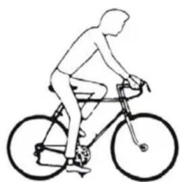
natural_image
Line drawing of a person riding a bicycle, no text or symbols presentnatural_image
Technical line drawing of a mechanical device with no visible text or symbolsnatural_image
Technical diagram of a mechanical device with no visible text, numbers, or symbolsnatural_image
Line drawing of a bicycle brake lever mechanism with no text or symbols-
Framnav
-
Kona
-
Kona
-
Framgaffel
-
Axellåsbricka
-
Axel
-
Mutter
natural_image
Technical line drawing of a mechanical device with a cylindrical component and a connected lever (no text or symbols)
natural_image
Diagram of a mechanical linkage or wheel assembly with a hand operating a tool, showing no text or symbols.natural_image
Line drawing of a mechanical device with a cylindrical body and attached lever (no text or symbols)
natural_image
Mechanical diagram showing a gear mechanism with an arrow indicating rotational motion (no text or symbols)natural_image
Line drawing of a person riding a bicycle with a wheel and bicycle (no text or symbols)
natural_image
Line drawing of a person riding a bicycle, no text or symbols presentnatural_image
Technical line drawing of a mechanical device with no visible text or symbolsnatural_image
Technical line drawing of a mechanical device with no visible text or symbolsJuster bremseklossenes avstand til felgsiden med fjærjusteringsskruene.
3

natural_image
Line drawing of a bicycle lever handle with adjustment arrows indicating rotational motion (no text or symbols)VEDLIKEHOLD AV BREMSER
Felgbrems
-
Fornav
-
Kjegle
-
Kjegle
-
Forgaffel
-
Aksellåseskive
-
Aksel
-
Mutter
A Siodełko H Rama roweru
natural_image
Technical line drawing of a mechanical device with a cylindrical component and a connected lever (no text or symbols)
natural_image
Diagram of a mechanical device with a rotating wheel and lever mechanism (no text or symbols)natural_image
Line drawing of a mechanical device with a cylindrical body and lever, no text or symbols present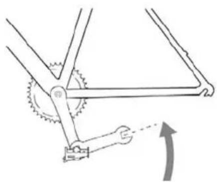
natural_image
Mechanical diagram showing a gear mechanism with a hand operating a shaft and a curved arrow indicating rotation (no text or symbols)natural_image
Line drawing of a person riding a bicycle, no text or symbols present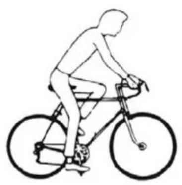
natural_image
Line drawing of a person riding a bicycle, no text or symbols presentnatural_image
Technical diagram of a mechanical device with directional arrows indicating motion or flow (no text or symbols)natural_image
Technical diagram of a mechanical device with no visible text, numbers, or symbolsnatural_image
Line drawing of a mechanical lever mechanism with no text or symbolsRead the operating instructions carefully before use!
Please retain for future reference.
Check the following items before each use
- Screw joints and components are tightened properly and not worn or damaged.
- The sitting position is comfortable.
• The brakes work adequately. - The steering is not binding or loose.
- The wheels are not warped and the wheel bearings are correctly adjusted.
- The wheels are correctly secured to the rear/front forks.
- The tyres are in good condition and have the correct air pressure.
- The pedals are correctly secured to the crank arms.
- The gears are properly adjusted.
- All reflectors are fitted.
- Following adjustment, make sure that all screw joints are correctly tightened and that the cables are undamaged and correctly routed along the frame.
- We recommend that you leave your bike in at the cycle repair shop every 6 months for a service (more frequently if you cycle a lot or exert the bike for heavy loads). Complete the service record after each service.
Road safety
- Do not cycle on the same side as oncoming traffic.
- Do not cycle 2-deep.
- Do not take anyone on the bike which is not equipped for this.
- Do not swerve out onto the road.
- Do not hang anything on the handlebars that will make it difficult to steer or that could get caught in the front wheel.
-
Do not hold onto another vehicle.
-
Do not cycle too close to the vehicle in front.
• Cycling in the rain or on a wet road:
— The effect of the brakes is reduced in water and on ice.
– Cycle more slowly in wet weather and brake earlier than you do in dry weather.
- If you cycle in the dark you must comply with the applicable legislation:
- The bike must have a front light with a white beam and a rear light with a red beam, in addition to the reflectors already on the bike.
- You should wear light clothing and a reflective jacket or similar.
- Check that the bike's reflectors are positioned correctly, properly secured, clean and not obscured. Replace damaged reflectors immediately.
- Any shock absorbers on the bike should be maintained by a cycle repair shop. See the shock-absorber manufacturer's operating instructions.
Owner's responsibility
The operating instructions describe how to cycle safely and keep the bike in good and faultless condition.
- Read and follow the operating instructions carefully. All major service work or adjustments to the bike should be carried out by a bicycle mechanic. Follow these instructions if you do not have access to a bicycle mechanic and would like to carry out the adjustments yourself.
IMPORTANT! All changes are made at your own risk.
- It can be dangerous to use the bike for freestyle cycling, stunts, competitions, cycling offroad etc. and you are personally responsible for any personal injury or other damage arising as a result of you using the bike in the above manner. The retailer renounces all responsibility in respect of the person buying the bike or a third party for consequential damage or specific damage.
- Familiarise yourself with the bike's components and accessories so that you can use them in the correct manner.
DESCRIPTION
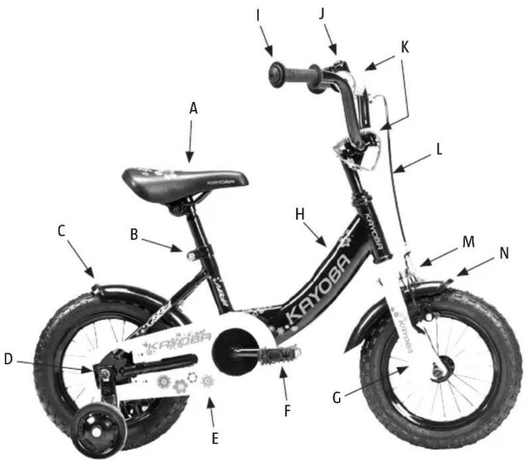
A Saddle H Bicycle frame
B Height adjustment saddle pillar I Child-compatible handle
C Rear mudguard J Bell
D Mounting support wheel K Protection (pads)
E Chainguard L Frame
F Pedal with reflex M Front V brakes
G Front fork N Front fork
INSTALLATION
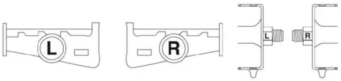
Fitting pedals
NOTE! The pedals are not identical – the pedal marked with an Ⓡ needs to be fitted to the right crank arm and the pedal marked Ⓛ to the left crank arm.
natural_image
Technical line drawing of a mechanical device with a cylindrical component and a connected lever (no text or symbols)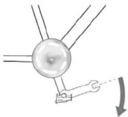
natural_image
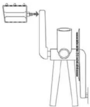
Diagram of a mechanical device with a circular component and a hand holding a tool, showing motion direction (no text or symbols)Fitting the right pedal (R): Screw the pedal into the crank arm on the chain side and tighten carefully with a spanner.
natural_image
Line drawing of a mechanical device with a cylindrical body and attached lever (no text or symbols)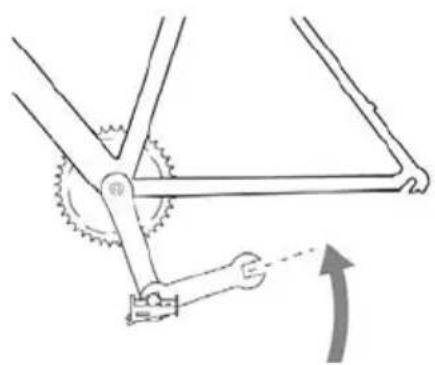
natural_image
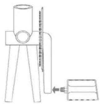
Mechanical diagram showing a gear mechanism with an arrow indicating rotational motion (no text or symbols)Fitting the left pedal (L): Screw in the pedal (anticlockwise) on the opposite side to the chain and tighten carefully with a spanner.
OPERATION
Sitting position
It is very important that the bike is correctly adjusted, from the point of view of both comfort and safety. There is information on the following pages on how you adjust your sitting position to make it comfortable, safe and effective.
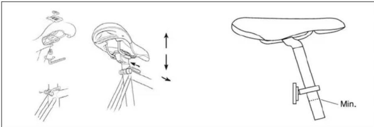
Saddle adjustment
Loosen the nut that attaches the saddle to the saddle pillar so that you can push the saddle backwards or forwards.
Adjust it to the desired position. The saddle angle can also be adjusted. We recommend that the saddle is horizontal.
Adjust the saddle height by loosening the clamp bolt attaching the saddle pillar to the seat tube. Set the saddle pillar to the desired height and tighten the clamp bolt.
IMPORTANT!
- The saddle pillar must be lower than the maximum height indicator. The maximum height indicator must not be visible.
- Tighten the saddle pillar's clamp bolt and nut to 30 Nm using a 6 mm Allen key or a 13 mm hex key. Check that the saddle pillar is securely attached by attempting to twist the saddle by hand. You must not be able to twist the saddle.
- Never cycle if the saddle or saddle pillar is not properly tightened.
Different saddle pillars are used for different types of saddle, which is why the attachments vary. Contact the retailer if you are unsure of how the saddle should be fitted.
Saddle angle
The saddle should preferably be horizontal. You can change the saddle angle, but the saddle should usually be horizontal. If you sit best with the saddle well angled, you should check if you can change any other setting instead.
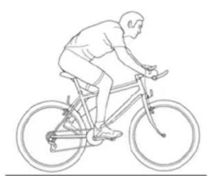
Saddle height
To check if you have the right saddle height, put one of the pedals into its lowest position. Sit on the saddle wearing flat shoes and check that the heel just reaches the pedal when you keep your leg straight. When you cycle with the pad of your foot on the pedal, your leg should be slightly bent when the pedal is at its lowest position (see fig.).
natural_image
Line drawing of a person riding a bicycle with a wheel and bicycle (no text or symbols)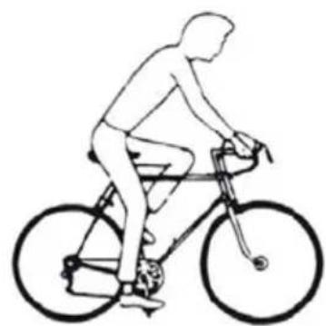
natural_image
Line drawing of a person riding a bicycle, no text or symbols presentThe position of the saddle above the pedals
Put the pad of one of your feet on the pedal with the crank arms horizontal. Adjust the position of the saddle forwards or backwards until the pedal is straight below the knee. Very small changes to the position of the saddle can affect both performance and comfort. Move the saddle a little at a time until you find the right position.
Handlebar post
Loosen the expander bolt on the lower part of the handlebar post until the expander wedge is loose. Carefully tap on the expander bolt if the wedge does not loosen by itself. Once the expander wedge has loosened, move the handlebar post upwards or downwards into a position where you are sitting comfortably and can easily reach the handlebars and brake levers. The handlebars should usually be at the same height as or slightly lower than the saddle. Check that the handlebar post is in line with the front wheel.
IMPORTANT! The handlebar post has an indicator to show how far it can project from the fork. This indicator must not be visible when the handlebar post is fitted. The handlebar post must be far enough into the fork that the indicator mark is not visible. Once you have found the right height, position the handlebars at a right angle to the front wheel. Tighten the expander bolt properly. It is extremely important that the expander bolt is properly tightened. Check that the handlebar post is properly secured by positioning yourself in front of the bike with your legs on either side of the front wheel. Squeeze the wheel with your legs and attempt to turn the handlebars sideways. The handlebar post must not rotate in the fork. Do not overtighten the handlebar post. There must be some give in it if you fall with the bike. Position the handles of the handlebars horizontally and tighten the clamp bolts properly.
Handlebar stem
The handlebar stem has two locking bolts at its rear end, which clamp around the fork tube. Loosen the bolts and position the handlebar stem so that it is in line with the front wheel. Then retighten the locking bolts.
IMPORTANT! Do not adjust the upper compression bolt. This is set so as to eliminate bearing play. If it is overtightened, this could result in wear.
Handlebar post
- Handlebar post expander
- Clamp bolt
- Handlebar maximum height indicator
Position of handlebars
Position the handlebars so that you can easily reach the gear controls and brake levers. Attempt to find a sitting position where your hands rest lightly on the handlebars. If you put too much weight on the handlebars this leads to strain on the wrists and forearms. Remember to tighten all screw joints after adjustment.
NOTE! NEVER RAISE THE HANDLEBAR POST OR SADDLE PILLAR ABOVE THE MAXIMUM HEIGHT INDICATOR.
Adjustment of cotterless crankset
IMPORTANT! Check whether the bike's chain sprockets and crank arms are of the cotterless type. If this is the case, check that the nuts securing them to the crankset are properly tightened. We recommend that you check that the nuts are properly tightened once you have been using the bike for two weeks and then at three-monthly intervals.
BRAKES
WARNING It is very important that you understand how the bike's brakes work. If you use the brakes incorrectly you could lose control of the bike and seriously injure yourself. Different bikes may behave in different ways when you brake, so it is important that you learn how the bike behaves in different situations and how hard you need to pull on the brake levers. Read the operating instructions and practice cycling and braking. Contact the retailer if you require further information.
You can use the brake handles on the left-hand side of the handlebars to brake the bike's front wheel. Pedal backwards to brake the rear wheel.
Safe braking
- Brake a bit earlier with the rear brake than with the front break.
- Never brake using the front brake when you are turning. It is particularly important that you bear this in mind when you are doing a tight turn or cycling on a loose surface.
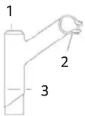
V brakes
1
natural_image
Technical diagram of a mechanical device with directional arrows indicating motion or force (no text or symbols)Insert the cable through the cable guide and set a distance of 2 mm between the brake pads and the sides of the rim. Tighten the cable fastening screw.
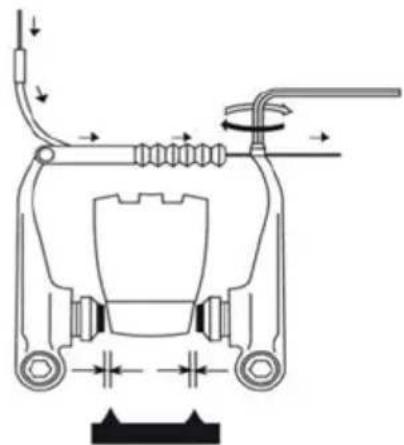
2
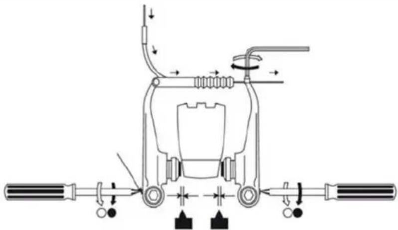
natural_image
Technical diagram of a mechanical device with no visible text, numbers, or symbolsAdjust the distance between the brake pads and sides of the rim using the spring adjuster screws.
3
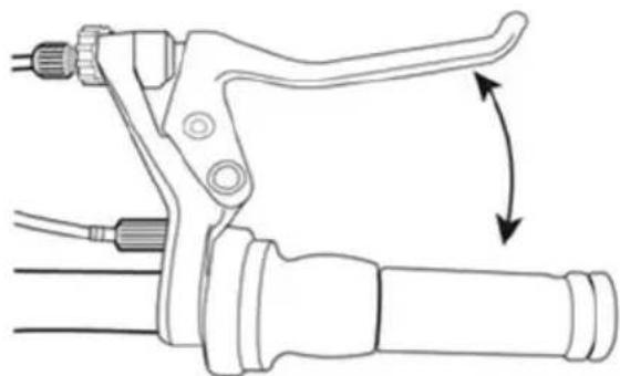
natural_image
Line drawing of a bicycle lever handle with adjustment arrows indicating rotational motion (no text or symbols)Press the brake levers about ten times to make sure that everything is working correctly and that the distance between the brake pads and the sides of the rim is correct before you use the bike.
IMPORTANT!
- If you brake too hard with the front break, you may be thrown off the bike.
- The brakes are less effective in wet conditions. Cycle more slowly and brake earlier in wet conditions.
- Do not cycle if the brakes are not working correctly.
Check the brake adjustment and lubricate the brake springs and pivots regularly. Lubricate the exposed part of the cable to protect against corrosion. If it is difficult to brake, this is often because the cables are insufficiently lubricated. The brake cable must be removed for lubrication. We recommend that you allow a bicycle mechanic lubricate the brake cables.
NOTE! In order for the brakes to be applied evenly, the wheels must not be warped. They must be correctly adjusted and the sides of the rim must be even and without any markings. The brake linings must be correctly adjusted to the sides of the rim. Contact the retailer if you are unsure about how to adjust the wheels or brakes. Protect the end of the cable with end caps so that the cable does not fray.
IMPORTANT! The brakes must not bind or remain in contact with the rim when you release the brake lever. If the brakes bind, check that the callipers, cables and brake levers are clean and lubricated. Take the bike to the retailer if the brakes bind despite these components being clean and lubricated.
TYRE CARE AND WHEEL ADJUSTMENT
- In order for the bike's tyres to function well and last a long time, it is important that they have the correct air pressure, which is indicated on the side of the tyre.
- Locking the brakes and skidding wears out the tyres.
- The tyres must not come into contact with oil, petrol, paraffin or other agents that dissolve rubber.
- Check that the wheels are not warped and that they are correctly aligned so that the side of the tyre does not come into contact with the frame or front fork.
- Check also that the tyres are not worn or have cracks. Ensure that the tyre tread has not been worn down and that there is no damage, cracks or uneven wear on the tyre. Replace a worn or damaged tyre immediately.
- If you cycle over sharp stones, holes in the road or onto kerbs the tyres may puncture.
- If the bike is to be stored away for a long period we recommend that you remove the wheels to prevent them becoming warped.
- Pump the tyres with a foot pump or hand pump with a suitable valve connection. Check the pressure with a pressure gauge.
- Check regularly that the spokes are correctly tensioned. Check often if you cycle a lot on uneven roads.
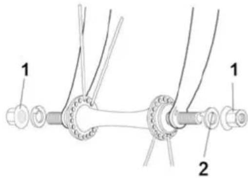
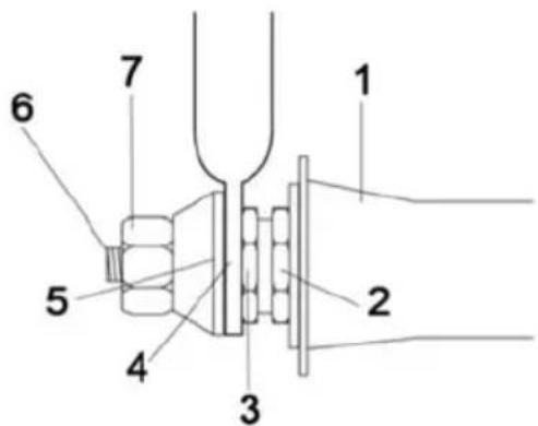
Front wheel
Remove wheel axle nuts, washers and any axle locking washer. The conical bearing of the wheel axle must be adjusted so that the wheel spins easily. The conical locking nut must be properly tightened to the cone of the wheel axle so that the wheel cannot come loose. Hold the front wheel between the front fork legs and position it so that the axle locking washer and its serrations are in contact with the opening in the front fork or that the standard washers are in the correct position against the front wheel if the bike does not have wheel axle holders. Move locking washers over to the side of the wheel that is close to the fork legs if the wheel is not centred.
IMPORTANT!
The front wheel axle locking washers or washers must be positioned in the openings in the fork legs so that the wheel sits securely in the front fork.
-
Nut
-
Axle locking washer
-
Front hub
-
Cone
-
Cone
-
Front fork
-
Axle locking washer
-
Axle
-
Nut
Jula reserves the right to make changes. In the event of problems, please contact our service department. www.jula.com