99-5835G - Uncategorized AXESS - Free user manual and instructions
Find the device manual for free 99-5835G AXESS in PDF.

User questions about 99-5835G AXESS
0 question about this device. Answer the ones you know or ask your own.
Ask a new question about this device
Download the instructions for your Uncategorized in PDF format for free! Find your manual 99-5835G - AXESS and take your electronic device back in hand. On this page are published all the documents necessary for the use of your device. 99-5835G by AXESS.
USER MANUAL 99-5835G AXESS
natural_image
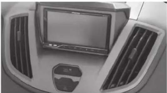
Front view of a car dashboard with air vent and monitor (no visible text or symbols)Ford Transit 2015-2019\*
*For non-navigation model
Visit NetraOnline.com for more detailed information about the product and up-to-date vehicle specific applications
KIT FEATURES
• ISO DIN radio provision with pocket
- ISO DDIN radio provision
• Radio trim panel is painted gray
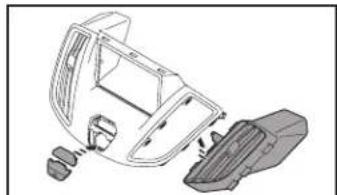
KIT COMPONENTS
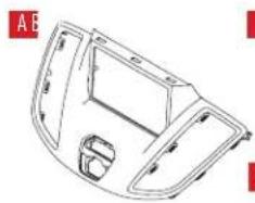
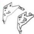
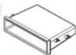
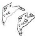
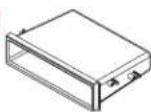
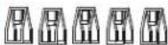
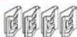
• A) Radio trim panel • B) Dash panel • C) Radio brackets • D) Pocket • E) Airbag light • F) (4) #8 x 3/8" Phillips truss head screws
• G) (2) #8 x 3/8" Phillips pan head screws • H) (3) Metal "U" panel clips • I) (5) Metal "D" panel clips • J) (4) Small metal "D" panel clips • K) (4) Plastic panel clips
natural_image
Technical line drawing of a car interior frame (no text or symbols)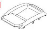
D
E


G

H
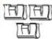
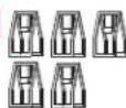
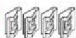
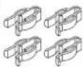
TABLE OF CONTENTS
Dash Disassembly 2
Kit Preparation 2
Kit Assembly
-ISO DIN radio provision with pocket ....3
-ISO DDIN radio provision ....3
Final Assembly 3
WIRING & ANTENNA CONNECTIONS (sold separately)
Wiring Harness: 70-5524
Antenna Adapter: 40-EU10
Visit MetraOnline.com for audio/video and steering wheel control interface options.
TOOLS REQUIRED
- Panel removal tool • Phillips screwdriver
- Socket wrench • T-20 Torx driver
Attention: With the key out of the ignition, disconnect the negative battery terminal before installing this product. Ensure that all installation connections are secure before cycling the ignition to test this product.
DASH DISASSEMBLY KIT PREPA
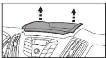
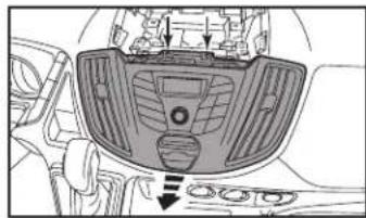
- Unclip the dash panel above the radio. (Figure A)
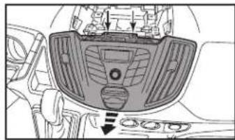
- Remove (2) T-20 Torx screws securing the factory radio/trim panel. (Figure B)
- Unclip the factory radio/trim panel from the dash, unplug and remove. (Figure B)
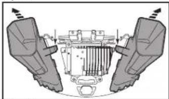
- Remove (1) T-20 Torx screw per vent then unclip and remove the vents from the factory radio/trim panel. (Figure C)
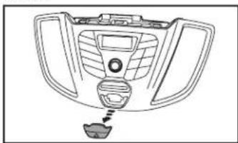
- Unclip and remove the hazard switch assembly from the factory radio/trim panel. (Figure D)
Continue to Kit Preparation
natural_image
Top-down view of a car dashboard with airflow indicators (no text or symbols)(Figure A) (Figure D)
natural_image
Top-down view of a car dashboard with air vent and control buttons (no text or symbols visible)(Figure B)
natural_image
Diagram of a vehicle's rear view showing steering wheel, dashboard, and engine components (no text or labels)(Figure C)
natural_image
Line drawing of a car intake manifold with no text or symbolsTION
- Secure the factory vents to the radio trim panel using the (2) #8 x 3/8" Phillips pan head screws provided. (Figure A)
- Snap the factory hazard button into the radio trim panel. An airbag light blank has been included for models without a passenger airbag indicator. (Figure A)
natural_image
Technical line drawing of a car interior frame with handle and seat components (no text or symbols)(Figure A)
(Figure B)
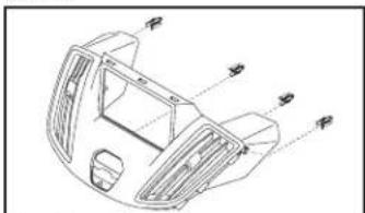
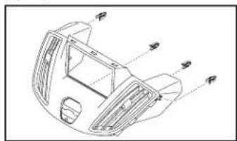
- Attach the (4) plastic panel clips provided to the radio trim panel. (Figure B)
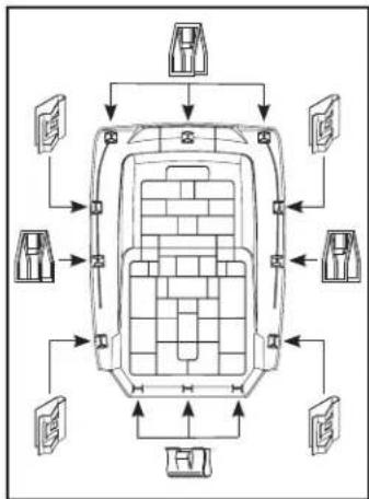
- Attach the (12) metal panel clips provided to the dash panel. (Figure C)
Continue to Kit Assembly
flowchart
graph TD
    A["Top Floor"] --> B["Left Side"]
    A --> C["Right Side"]
    A --> D["Left Side"]
    A --> E["Right Side"]
    B --> F["Bottom Floor"]
    C --> G["Left Side"]
    D --> H["Right Side"]
    E --> I["Left Side"]
    F --> J["Top Floor"]
    G --> K["Left Side"]
    H --> L["Right Side"]
    I --> M["Left Side"]
(Figure C)
KIT ASSEMBLY FINAL ASSEMI
ISO DIN radio provision with pocket
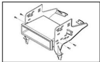
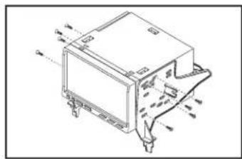
- Attach the pocket to the radio brackets using the (4) supplied #8 x 3/8" Phillips truss head screws. (Figure A)
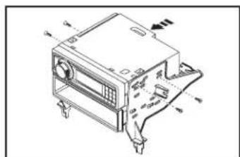
- Remove the metal DIN sleeve and trim ring from the aftermarket radio.
- Slide the radio into the completed assembly and then secure it using the screws supplied with the radio. (Figure B)
Continue to Final Assembly
ISO DDIN radio provision
- Attach the radio brackets to the radio using screws supplied with the radio. (Figure C)
Continue to Final Assembly
natural_image
Technical line drawing of a mechanical assembly with labeled components (no text or symbols)(Figure A)

natural_image
Technical line drawing of a mechanical device with mounting brackets and a control panel (no text or symbols)(Figure B)
natural_image
Technical line drawing of an electronic device with mounting holes and internal components (no text or symbols)(Figure C)
- Cut the shaded portion from the sub-dash of the vehicle to allow the radio to fit. (Figure A)
- Locate the factory wiring harness and antenna connector in the dash and complete all necessary connections to the radio. Metra recommends using the proper mating adapter from Metra and/or AXXESS. Test the radio for proper operation.
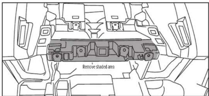
(Figure A)
Having difficulties? We're here to help.

our Tech Support line at:
386-257-1187

mail at:
techsupport@metra-autosound.com
Tech Support Hours (Eastern Standard Time)
Monday - Friday: 9:00 AM - 7:00 PM
Saturday: 10:00 AM - 7:00 PM
Sunday: 10:00 AM - 4:00 PM

KNOWLEDGE IS POWER
Enhance your installation and fabrication skills by supplying in the most recognized and supported
mobile electronics school in our industry.
Log onto www.installennstitute.com or call
800-354-6782 for more information and take steps toward a better tomorrow.

Metra recommends MECP certified technicians
natural_image
Front view of a car dashboard with air grilles and a central touchscreen display (no visible text or symbols)Ford Transit 2015-2019\*
The image is too blurry to recognize any text content.
D
E


A
G

H


INDICE
natural_image
Top-down view of a car dashboard with two upward arrows indicating direction (no text or symbols)(Figura A)
natural_image
Top-down view of a car dashboard with air vent and control buttons (no text or symbols visible)(Figura B)

natural_image
Diagram of a vehicle's rear view showing two seats and a central engine compartment (no text or labels)(Figura C)

natural_image
Line drawing of a car intake manifold with no text or symbols(Figure D)
PREPARACIÓN DEL KIT
natural_image
Technical line drawing of a vehicle chassis with internal components and mounting brackets (no text or symbols)(Figura A)
natural_image
Technical line drawing of a car interior frame with no visible text or symbols(Figura B)
flowchart
graph TD
    A["Top Room"] --> B["Left Room"]
    A --> C["Right Room"]
    B --> D["Left Room"]
    B --> E["Right Room"]
    C --> F["Left Room"]
    C --> G["Right Room"]
    D --> H["Bottom Room"]
    D --> I["Left Room"]
    E --> J["Right Room"]
    E --> K["Left Room"]
    F --> L["Bottom Room"]
    F --> M["Left Room"]
    G --> N["Right Room"]
    G --> O["Left Room"]
(Figura C)
ENSAMBLE DEL KIT
natural_image
Technical line drawing of a mechanical assembly with labeled components (no text or symbols)(Figura A)
natural_image
Technical line drawing of a mechanical device with mounting brackets and a control panel (no text or symbols)(Figura B)

natural_image
Technical line drawing of a mechanical component with mounting holes and internal structure (no text or symbols)(Figura C)
ENSAMBLE FINAL
Mávil (Mobile Electronics
Certification Program, MECP).