
SCANTOUCH 210 - To scan NIKON - Free user manual and instructions
Find the device manual for free SCANTOUCH 210 NIKON in PDF.

| Product type | Flatbed scanner |
| Brand | Nikon |
| Model | ScanTouch 210 (AX-210) |
| Optical resolution | 1200 x 2400 dpi |
| Color depth | 48 bits (internal) |
| Maximum scanning area | 216 x 297 mm (A4) |
| Interface | USB 1.1 / SCSI (depending on version) |
| Power supply | External power adapter (12 V DC, 1.25 A) |
| Power consumption | Operating: 12 W; standby: 3 W |
| Dimensions (W x D x H) | 295 x 510 x 85 mm |
| Weight | Approximately 4.5 kg |
| Main functions | Scanning documents and photos, copying, scanning transparencies (with optional adapter) |
| Included software | Nikon Scan, retouching software |
| Compatible operating systems | Windows 98/Me/2000/XP, Mac OS 9.x |
| Maintenance and cleaning | Clean the glass with a soft, lint-free cloth. Avoid solvents. Unplug before cleaning. |
| Safety | Do not expose to moisture. Use the provided adapter. Unplug during thunderstorms. |
| Spare parts and repairability | Fluorescent lamp replaceable by a technician. Parts available from the manufacturer. |
| General information | Manufactured by Nikon Corporation, Japan. Compliant with CE standards. Class B number. |
Frequently Asked Questions - SCANTOUCH 210 NIKON
User questions about SCANTOUCH 210 NIKON
0 question about this device. Answer the ones you know or ask your own.
Ask a new question about this device
Download the instructions for your To scan in PDF format for free! Find your manual SCANTOUCH 210 - NIKON and take your electronic device back in hand. On this page are published all the documents necessary for the use of your device. SCANTOUCH 210 by NIKON.
USER MANUAL SCANTOUCH 210 NIKON
- The reproduction of all or part of this manual without our permission is prohibited.
- The information contained in this manual is subject to change without notice.
- We have made every effort to produce a perfect manual, but should you find any mistakes, we would be grateful if you would kindly let us know.
- We shall take no responsibility for consequences resulting from the operation of this product, despite the terms mentioned above.
Indication
The ⚠️ indications in this manual signify important safety precautions. In order to use this product safely, please read every section where these indications are placed before beginning operation of this product. These indications are also placed in the table of contents so users can find them easily.

Indication
The √ indications in this manual signify the need for caution when using the products. These indications are placed in sections that should be read by users before beginning operation, in order to avoid damage to the product.
Trademark Information
Macintosh is a registered trademark of Apple Computer, Inc.
Microsoft is a registered trademark and Windows is a trademark of Microsoft Corporation.
IBM PC/AT is a trademark of International Business Machines Corporation.
Other brand or product names are the trademarks or registered trademarks of their respective holders.
Important Safeguard
- Read all of these instructions.
- Save these instructions for later use.
- Follow all warnings and instructions marked on the product.
- When replacement parts are required, be sure the service technician has used replacement parts specified by the manufacturer and that have the same characteristics as the original parts. Unauthorized substitutions may result in fire, electric shock, or other hazards.
- Do not use this product near water or in rainy or moist conditions.
• To avoid serious damage, be sure to place the product on a stable surface. - The product should be operated only from the type of power source indicated on the marketing label.
- Do not attempt to service this product yourself as opening or removing the enclosure may expose you to dangerous voltage or other hazards.
- This unit has an autoranging input circuitry suitable for 120VAC and 240VAC.
- According to IEC 704-1:1982, the sound pressure level at the operator's position is equal or less than 70dB(A).
Federal Communications Commission (FCC) Radio Frequency Interference Statement
This equipment has been tested and found to comply with the limits for a Class B digital device, pursuant to Part 15 of the FCC Rules. These limits are designed to provide reasonable protection against harmful interference in a residential installation. This equipment generates, uses, and can radiate radio frequency energy and, if not installed and used in accordance with the instructions, may cause harmful interference to radio communications. However, there is no guarantee that interference will not occur in a particular installation. If this equipment does cause harmful interference to radio or television reception, which can be determined by turning the equipment off and on, the user is encouraged to try to correct the interference by one or more of the following measures:
• Reorient or relocate the receiving antenna.
- Increase the separation between the equipment and receiver.
- Connect the equipment into an outlet on a circuit different from that to which the receiver is connected.
- Consult the dealer or an experienced radio/TV technician for help.
CAUTION
Modifications
The FCC requires the user to be notified that any changes or modifications made to this device that are not expressly approved by Nikon Corporation may void the user's authority to operate the equipment.
SCSI Cable
Please use the SCSI cable described on page 12 of this manual. Using other interface cables may exceed the limits of the class B Part 15 of FCC rules.
Notice for customers in Canada
This class B digital apparatus meets all requirements of the Canadian Interference Causing Equipment Regulations.
ATTENTION
When Taking the Unit Out of The Country
The use of this product may violate local laws and restrictions in some countries. If this is the case, we cannot bear any responsibility for any violations resulting from the use of this product.
Notice concerning prohibition of copying or reproduction
Note that simply being in possession of material which has been copied or reproduced by means of a scanner may be punishable by law.
- Items prohibited by law from being copied or reproduced
Do not copy or reproduce paper money, coins, securities, government bonds, or local government bonds, even if such copies or reproductions are stamped “Sample”.
The copying or reproduction of paper money, coins, or securities which are circulated in a foreign country is prohibited.
The copying or reproduction of unused postage stamps or post cards issued by the government without obtaining approval from the government is prohibited.
The copying or reproduction of stamps issued by the government and certified documents stipulated by law is prohibited.
- Cautions on certain copies and reproductions
The government has issued cautions on copies or reproductions of securities issued by private companies (shares, bills, checks, gift certificates, etc.), commuter passes, or coupon tickets, except when a minimum of necessary copies are to be provided for business use by a company. Also, do not copy or reproduce passports issued by the government, licenses issued by public agencies and private groups, ID cards, and tickets, such as passes and meal coupons.
• Comply with copyright notices
The copying or reproduction of works such as books, music, paintings, woodcut prints, maps, drawings, movies, and photographs which are copyrighted creative works is prohibited except when it is done for personal use at home or for similar restricted and non-commercial use.
Contents
1. Overview ...... 1
2. Before Operating the Scanner.... 2
2.1 Power Supply Precautions 2
2.2 ⚠ Handling Precautions ...... 4
2.3 ⚠️ If You Notice Anything Abnormal ...... 7
2.4 Storage and Operating Locations 7
2.5 ⚠ Transportation Precaution ...... 10
3. Parts Identification 11
3.1 Inspection.... 11
3.2 Components.... 11
3.3 Main Body 13
A Closer Look 13
Rear View 14
Unlocking the Scanner 15
4. Connecting the Scanner 16
4.1 Before Connection 16
4.2 Connecting the Power Cord 17
4.3 Connecting the SCSI Cable 19
Connecting to the Macintosh computer 20
Connecting to the IBM PC/AT or compatible computer .20
SCSI Chain Connection with Other Devices .... 21
4.4 Setting the SCSI ID 23
Contents
5. Operation 24
5.1 Turning on the Power 24
5.2 Setting a Document 26
6. Maintenance....29
6.1 Static Electricity Precautions 29
6.2 Cleaning 30
7. Troubleshooting 31
Appendix: Specifications.... 34
Index 36
1. Overview
Thank you for purchasing your Nikon Flatbed Scanner ScanTouch 210. This manual describes the procedures for unpacking, setting up, and connecting your scanner, with emphasis on hardware use and precautions. Please read this manual thoroughly to ensure proper operation of your scanner.
For an explanation of how to scan and reproduce images with the ScanTouch 210, please refer to the software manual.
We hope that you will find this manual helpful.
The ScanTouch 210 is a low priced, full-color flatbed scanner which can perform high-resolution, high-speed scans.
- The ScanTouch 210 has an optical resolution of 600 dpi x 1200 dpi and can achieve high resolutions of up to 9600 dpi x 9600 dpi through software interpolation.
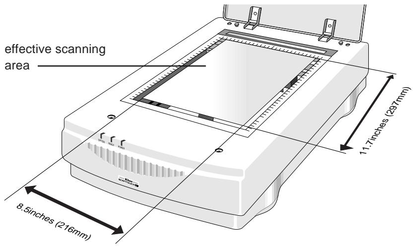
- The scanning area is 8.5 inches (216 mm) wide by 11.7 inches (297 mm) long, enabling scanning of letter-size documents.
- The ScanTouch 210 scans at very high speed, taking approximately 32 seconds to scan a color A4 document at a resolution of 600 dpi.
- Installing the optional Transparency Adapter enables scanning of transparencies.
- Installing the optional Auto Document Feeder enables consecutive scanning of multiple documents.
2. Before Operating the Scanner
2.1 Power Supply Precautions

In order to use the ScanTouch 210 safely and correctly, and to prevent problems, pay careful attention to the following points:
- Be sure to use an AC100V-120V/AC 200V - 240V, 50/60Hz power supply. The power cord should be changed according to the power voltage.
When using a power voltage of more than AC 125V
Use a suitable power cord compliant with the safety standards of the country in which it is used, with a plug of AC 250V, 15A rating (NEMA 6P-15), and insulation of at least SVT type and more than AWG18 in thickness.
When using a power voltage of AC 125V or less
Use a suitable power cord compliant with the safety standards of the country in which it is used, with a plug of AC 125V, 10A rating and insulation of at least SVT type and more than AWG18 in thickness.
- Be sure that the electrical outlet of the power supply is grounded. Carry out the grounding in common with the other machines it is being connected with. Unless common grounding is used, a ground loop will occur, which will cause electric shock and noise static.

natural_image
Illustration of a blue electrical plug next to two white electrical outlets (no text or symbols)* The shape of the plug depends on the country of use.
- Do not ground the unit to a gas pipe or a water pipe.
- When plugging in or unplugging the power cord, be sure to touch only the plug. Pulling on the cord can cause breakage and failure or electric shock.
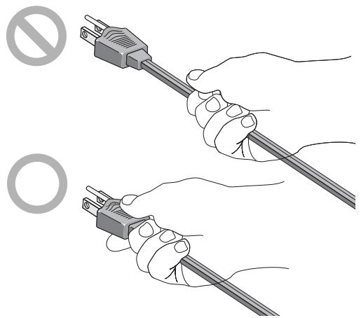
natural_image
Illustration of two hands holding a cable with a no-smoking symbol (no text or labels present)* The shape of the plug depends on the country of use.
- Do not connect the power cord to an extension cord, as this may cause a malfunction.
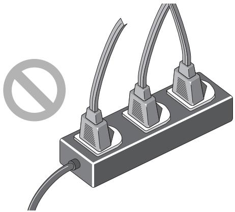
natural_image
Illustration of a three-pin electrical plug with two leads and a prohibition symbol (no text or labels)* The shape of the plug depends on the country of use.
2.2 Handling Precautions

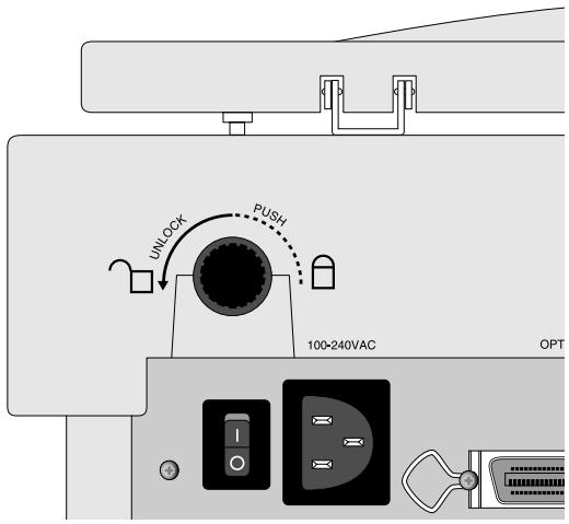
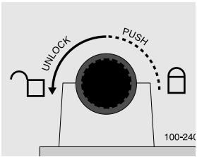
- Before turning the power on, ensure that the carriage lock is in the unlocked position (☐). When transporting the scanner, turn the carriage lock to the locked position (☐) to avoid damaging the internal optical assembly (see section 2.5).
Remarks

- Keep the unit horizontal, with the document cover facing upward, and ensure that it is placed on a flat and stable surface for use. Failure may result if the unit is not used in a flat and level horizontal position.
- On no account should you disassemble the unit. The high-voltage components inside the unit can cause electric shock.
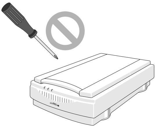
natural_image
Illustration of a screwdriver above a portable electronic device with a prohibition symbol (no text or labels)- Do not put any foreign objects inside the unit. If flammable objects, metal or water come into contact with the interior of the unit, failure, fire, and/or electric shock may result.
- Do not subject the unit to any strong shocks. This can cause breakage and failure.
- Do not place any heavy objects on the document setting glass, or push down on the glass, as this can cause breakage and failure.
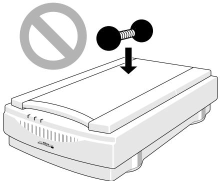
natural_image
Illustration of a printer with a prohibition symbol above it, no text or symbols present.2. Before Operating the Scanner
- Take care not to scratch the surface of the document setting glass, as this will affect the quality of the scanned images.
- Do not touch the pins of the SCSI connector, as this may result in static damage.
- Do not pull or bend the connecting cable, as this may cause the cable to break.
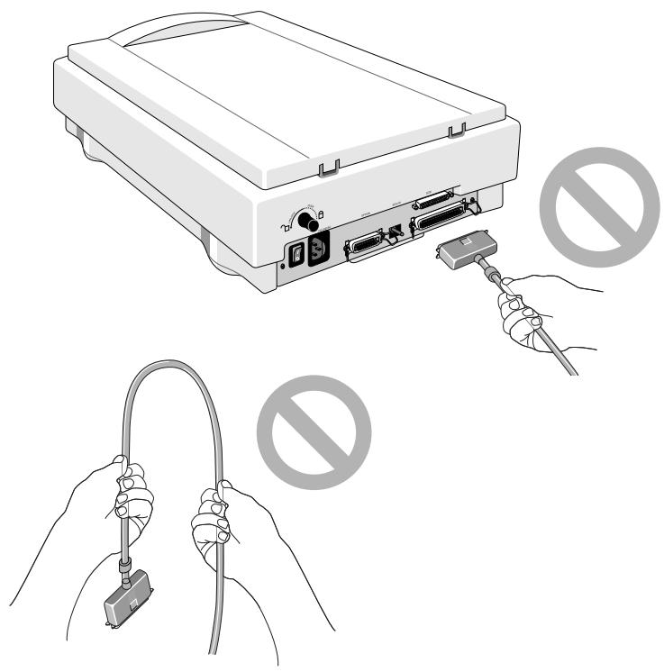
natural_image
Illustration of hands holding a cable and plug with no symbols, showing no text or labels present.- Do not move the unit or the document while the unit is scanning, as this may affect the quality of the scanned images.
- On no account should you look at the scanner's light source during operation, as this may result in eye damage.
- Please clean the unit periodically. Dust and dirt will affect the quality of the scanned images.
2.3 If You Notice Anything Abnormal

If you can notice unusual noise, odor or smoke, switch the unit off immediately and disconnect the power cord and the SCSI cable.
Contact your retailer or the Nikon sales representative in your country.
2.4 Storage and Operating Locations
Proper storage will ensure the long life of the unit.

Do not store or use where:
- The temperature is above 95^ F ( 35^ C) or below 50^ F ( 10^ C), the temperature changes drastically, or condensation occurs.
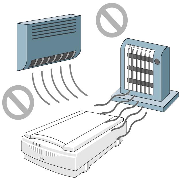
natural_image
Illustration of a printer emitting sound waves from a wall-mounted heater and a wall-mounted device, with no text or symbols present.2. Before Operating the Scanner
• The humidity exceeds 85%.
• The unit is exposed to direct sunlight.
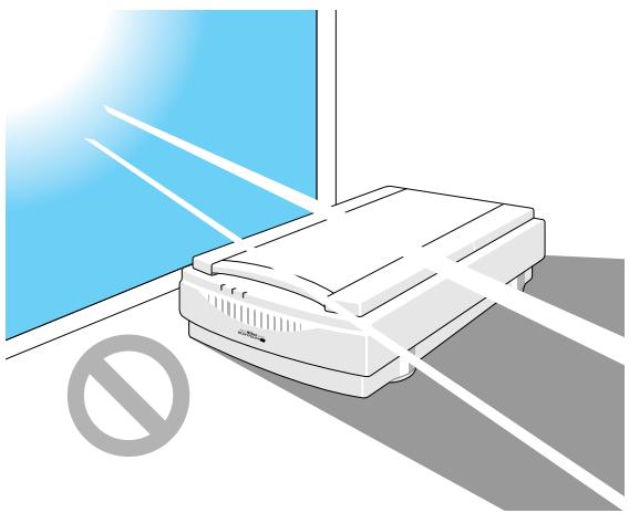
natural_image
Illustration of a printer with a blue background and a prohibition symbol (no text or labels)• The atmosphere is excessively dusty.
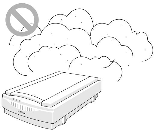
natural_image
Illustration of a printer emitting smoke with a prohibition symbol above (no text or labels)• The unit may be subjected to excessive vibration.
- The unit is exposed to electrical noise and interference from other equipment nearby.
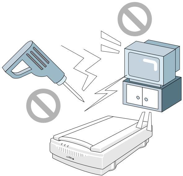
natural_image
Illustration of a handheld device emitting electric shock waves to a TV and printer, with no symbols or text present.- When installing the scanner, allow plenty of space around and above the unit to ensure smooth operation.
- When placing the unit on a table, ensure that the unit does not stick off the edge.
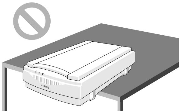
natural_image
Illustration of a printer with a prohibition symbol above it, no text or labels present.2.5 Transportation Precaution

When transporting the unit, lock the scanning carriage in place using the carriage lock, then pack the unit using the original packing material. If the original packing material is not available, be sure to pack it carefully, paying attention to possible vibrations or shocks that may affect the precision equipment during transportation. If transporting by air or delivery service, the scanner should be packed with particular care.
Before securing the locking screw, first switch the unit on. Once the scanning carriage has automatically returned to its ‘home’ position, (approximately 30 seconds after the unit is switched on), secure the locking screw.
3. Parts Identification
3.1 Inspection
Inspect the package to see whether any damage has occurred during shipment. If there is any damage to the package, please contact your retailer directly and do not unpack the unit.
3.2 Components
When you open the package, check whether all the items are present. If there are any missing items, please contact your retailer immediately.
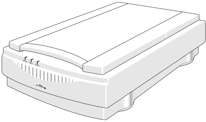
natural_image
Illustration of a white electronic device with ventilation slots and ports (no text or symbols)Main body (1)
3. Parts Identification

natural_image
Illustration of two connected broadband cables (no text or symbols)SCSI cable (1) (50-pin full-pitch 25-pin)

natural_image
Illustration of a U-shaped electrical connector with two connectors (no text or symbols)Power cord (1)
* The shape of the plug depends on the country of use.
Open Me First
User's manual(s) Software disk(s)
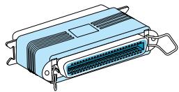
natural_image
Illustration of a blue plastic electronic component with a 24-pin connector (no text or symbols)Terminator (1)
3.3 Main Body
A Closer Look
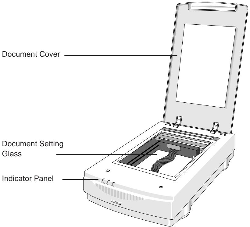
Document Cover: Plastic cover over the document setting glass which can be raised and lowered over a document.
Document Setting Glass: Glass surface on which the document or image should be placed.
Indicator Panel: Contains Power, Option, and Ready indicators. When you turn the power on and the test is initiated, the indicators will flash once. The Power indicator will then come on and the Ready indicator will blink. When the test is completed, the Power and Ready (and Option if an option is connected) indicators will glow steadily.
3. Parts Identification
Rear View
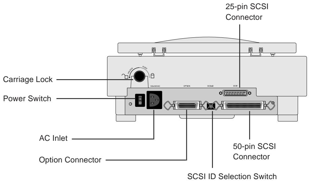
Carriage Lock: When transporting the unit, fasten the screw to lock the carriage.
AC Inlet: Connect to the AC power source with the power cord provided.
Power Switch: Directly turns the AC power on/off.
Option Connector: This connector is for use with a Transparency Adapter or an Automatic Document Feeder.
25-pin SCSI Connector: For 25-pin SCSI cable connection.
50-pin SCSI Connector: For 50-pin SCSI cable connection.
SCSI ID Selection Switch: Sets the SCSI ID number. Numbers 0 to 7 are shown and valid.
Unlocking the Scanner
Before turning the power on, ensure that the carriage lock is in the unlocked position (☐). When transporting the scanner, set the carriage lock to the locked position (☐) to avoid damaging the internal optics.

4. Connecting the Scanner
4.1 Before Connection
Before connecting the cables, confirm that all devices, including the computer system and the scanner, are turned off.

natural_image
Gray computer key with an exclamation mark and letter O (no text or symbols beyond the icon)Power OFF
For an IBM PC/AT or compatible in which a SCSI board has not been installed, install a SCSI board as explained in the manual supplied with the board.
Note: Make sure that the PC is powered off before installing the SCSI board.
When installing a SCSI board for the first time, be careful not to set conflicting I/O addresses, interrupt numbers, or graphic board DMA channels.
4.2 Connecting the Power Cord
Before connecting the power cord, confirm that the unit's power switch is in the off position.
Insert the female end of the supplied power cord into the AC inlet located on the rear panel, then insert the plug into the AC power outlet.
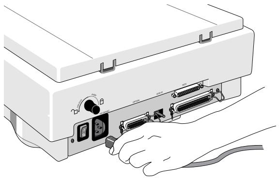
natural_image
Illustration of hands connecting to a computer monitor with attached cables (no text or symbols visible)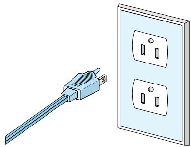
natural_image
Illustration of a blue electrical plug next to two white electrical outlets (no text or symbols)* The shape of the plug depends on the country of use.
4. Connecting the Scanner
Remarks

• The power source must be grounded.
- If possible, try to use an independent electric outlet. If the unit is connected to an outlet to which an electric household appliance, such as a vacuum cleaner or air-conditioner, is connected, the product may experience power source noise interference.
- Do not connect the power cord to an extension cord, as this may cause a malfunction.
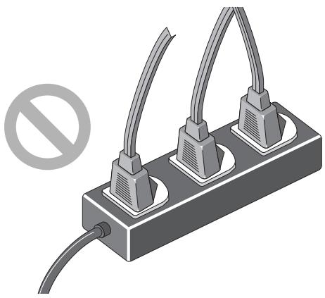
natural_image
Illustration of a three-pin electrical plug with two leads and a prohibition symbol (no text or labels)* The shape of the plug depends on the country of use.
4.3 Connecting the SCSI Cable
Before connecting the SCSI cable, confirm that all SCSI devices, including the computer system, have been turned off.

natural_image
Close-up of a gray computer key with an exclamation mark and letter O (no text or symbols beyond the icon)Power OFF
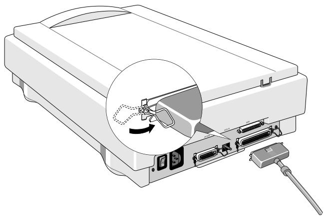
Connect the unit to the computer using the SCSI cable provided. After attaching the connector, be sure to lock it in place. You can connect the SCSI cable to either of the SCSI connectors (50-pin and 25-pin) on the rear panel of the unit.
Caution: Do not touch the pins of the SCSI connector. This can result in static damage.
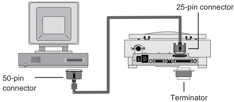
Connecting to the Macintosh computer
When connecting the unit directly to your Macintosh computer, connect the 25-pin connector to the computer, and the 50-pin connector to the unit. If the unit is the only connected SCSI device, or if the unit is connected at the end of the SCSI chain, attach the supplied SCSI terminator between the 50-pin SCSI connector on the unit and the SCSI cable, as shown below.
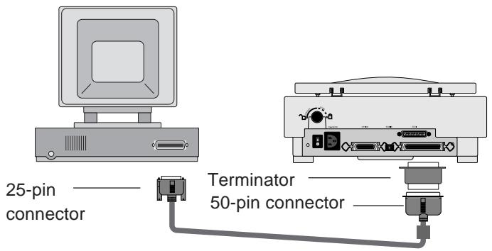
Connecting to the IBM PC/AT or compatible computer
When connecting the unit directly to the IBM PC/AT or compatible computer, connect the 50-pin connector to the computer, and the 25-pin connector to the unit. If the unit is the only connected SCSI device, or if the unit is connected at the end of the SCSI chain, attach the supplied SCSI terminator to the 50-pin SCSI connector on the unit, as shown below.
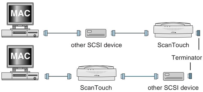
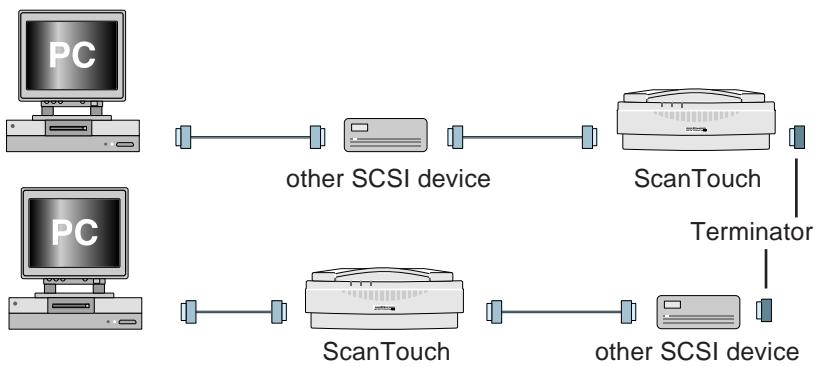
SCSI Chain Connection with Other Devices
If your ScanTouch is connected at the end of the SCSI chain, install the supplied terminator to the other SCSI connector on the rear of ScanTouch. If your ScanTouch is connected between the other SCSI devices, no terminator on ScanTouch is necessary.
Since the terminator is built into the host computer in most cases, the host computer should be at the end of the SCSI chain. Some notebook computers require a terminator to be attached outside the computer; please refer to the operation manual for the computer.
Note: The SCSI cable used for SCSI connection should be of high-impedance type.
flowchart
graph LR
    A["MAC"] --> B["other SCSI device"]
    C["MAC"] --> D["ScanTouch"]
    D --> E["other SCSI device"]
    B --> F["ScanTouch"]
    D --> G["other SCSI device"]
    H["ScanTouch"] --> I["Terminator"]
flowchart
graph TD
    A["PC"] --> B["other SCSI device"]
    C["PC"] --> D["ScanTouch"]
    B --> E["ScanTouch"]
    D --> F["other SCSI device"]
    E --> G["Terminator"]
    F --> G["Terminator"]

Remarks
- The maximum number of SCSI devices that can be connected to one computer is eight including the CPU. When using the scanner with a host computer with a built-in SCSI hard disk or built-in CD-ROM, note that SCSI ID numbers have been preassigned for the host CPU and the SCSI devices.
- The SCSI cable must not be extended beyond a total length of 19 feet (6 meters), or else failure may result.
- Terminators must be attached to the devices located at both ends of the SCSI chain.
If the host computer is a Macintosh, the Macintosh itself will provide termination at one end of the chain.
If the host computer is an IBM PC/AT or compatible, equipped with a SCSI board, the SCSI board itself will provide termination at one end of the chain.
Note that when a SCSI chain connection is made inside a computer, the end of the SCSI device inside the computer will become the end terminal.
- Before installing a SCSI board, be sure to read the user's manual provided with the board. The numbers for the I/O address, interrupt level (INT) and DMA channel might conflict with other interface boards and peripheral devices. If so, change them as explained in the manual.
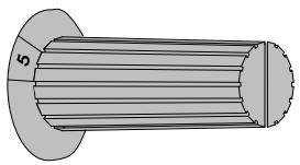
4.4 Setting the SCSI ID
The SCSI ID for the ScanTouch 210 is set at “5” when the unit is shipped. If other SCSI devices are connected to your computer, make sure that the SCSI ID for the ScanTouch 210 is different from those assigned to other SCSI devices.
natural_image
Technical drawing of a threaded bolt with flange and central hub (no text or symbols)Note that in the case of a host computer which has a built-in SCSI hard disk or built-in CD-ROM, the ID numbers of the host CPU and each SCSI device have already been assigned.
If the IDs are duplicated, you must change the ID number of the other SCSI device or of the ScanTouch 210 to avoid any conflict.
Remarks

- To change the ID, confirm that the scanner power is off. The ID cannot be changed when the power is on.
- Do not use SCSI ID 8 and 9 or A through F on your scanner. They are for factory use only.
- As 7 has been assigned for the CPU and 0 has been assigned to the built-in hard disk for a Macintosh, and 0 and 7 have also been assigned to other personal computer systems, any number from 1 to 6 is recommended for the ID number.
- If conflicting ID numbers are assigned, your system might not function, or important data on the hard disk might be destroyed. It is therefore essential to check the ID numbers carefully before connecting the scanner.
5. Operation
5. Operation
5.1 Turning on the Power
Before turning the power on, confirm that the carriage lock is in the unlocked position.
Turn the scanner on first, the other SCSI devices next, and the host computer last.

natural_image
Gray computer key with an exclamation mark and letter O (no text or symbols beyond the icon)Power OFF

natural_image
Close-up of a gray computer key with an 'I' and 'O' symbol (no additional text or labels)Power ON
The scanner automatically performs a simple self test each time it is turned on to help spot major system errors in the scanner itself. Once the scanner has been unpacked and the shipping restraint has been removed, the scanner is ready to perform this test.
When the test is initiated, the Power, Ready, and Option indicators will flash once. The Power indicator will then come on and the ready indicator will blink. When the test is completed, the Power and Ready indicators will glow steadily.

Remarks

- To turn the power off, turn the host computer off first, the other SCSI devices next, and the ScanTouch last (reverse order from switching on).
- Once the power is turned off, please wait five seconds or more before turning the power on again.
- Do not turn the power off while the scanner is scanning.
5.2 Setting a Document
- The scanning area is 8.5 inches (216 mm) wide by 11.7 inches (297 mm) long, enabling scanning of letter-size documents.
- For scanning transparency films for OHPs (overhead transparencies), place a sheet of white paper on top.
- If the document is curled or creased, make sure that it is straightened and flattened before setting it in position.
- If the paper has staples or clips attached, make sure they do not scratch the surface of the glass.
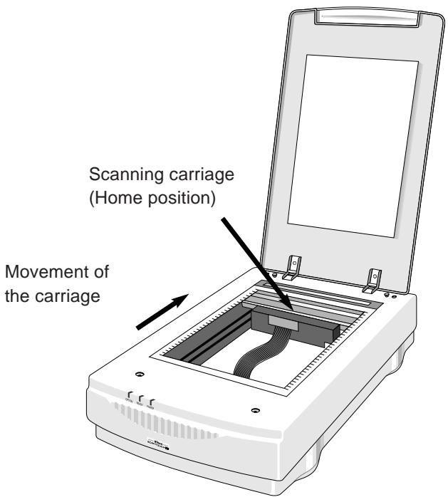
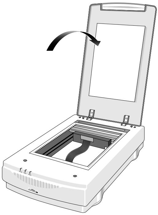
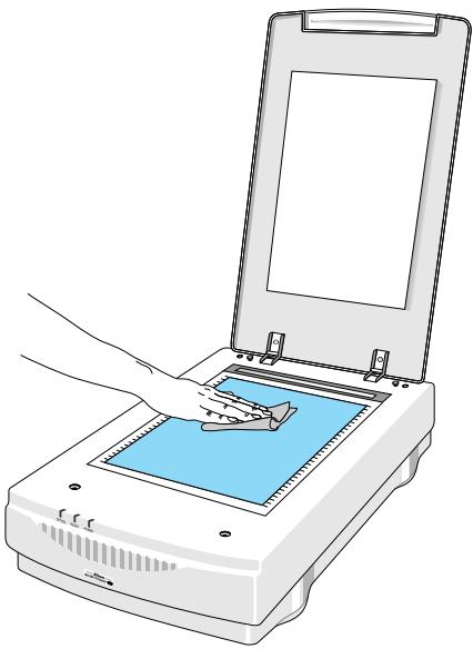
Step 1
Open the document cover gently.
natural_image
Illustration of a scanner with an open lid and internal structure, showing no text or symbols.5. Operation
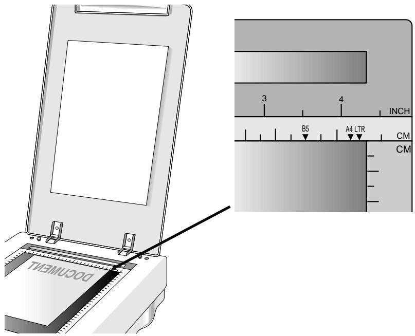
Step 2
Position a document with the side to be scanned facing down, aligning it with the appropriate mark on the ruler.

Cautions
- When positioning a document that has staples or clips attached, ensure that they do not scratch the surface of the document setting glass.
- Make sure that the glass is free of dust or dirt, as this may affect the quality of the scanned images.
- When positioning a document, make sure you do not touch the glass, as this may affect the quality of the scanned images.
Step 3
Close the document cover gently.
6. Maintenance
With the exception of periodic cleaning or lamp replacement, the scanner is virtually maintenance free. The following sections give the procedures for basic maintenance of the scanner.
6.1 Static Electricity Precautions

Static electricity is a constant danger to computer systems. The charge that can build up in your body may be strong enough to damage electronic components on the scanner's printed circuit board or the computer's interface card. Therefore, it is important to observe basic precautions whenever handling electronic components for your computer. Although areas with high humidity are much less prone to static electricity, it is best to always take precautions against accidental damage that can result in expensive repairs.
The following measures should generally be enough to protect your equipment from static discharge.
Discharge any static electricity that may have built up in your body by touching a grounded or antistatic surface. For example, touch some large metal object or the silver-toned expansion slot covers at the rear of your computer's case. Be sure to do this immediately before removing any components from their antistatic bag.
When handling any electronic components, be sure to carefully avoid touching any metal part of the component. Avoid touching any of the gold “fingers” that plug into the expansion slot. It is best to handle system components either by their edges or by the mounting bracket which attaches to the slot opening in the rear of the case.
Follow the above to the best of your ability. Excessive caution is not necessary, simply take reasonable care.
6. Maintenance
6.2 Cleaning
Regularly cleaning the document setting glass will ensure that dirt or smudges will not reduce the quality of your scanned images. Before you clean the glass, make sure the scanner is turned off and the power cord is unplugged.
Clean the document setting glass and document cover with a soft damp cloth and a mild detergent.
natural_image
Illustration of a hand inserting a small object into a device with a blue screen (no text or symbols visible)Note: Avoid spraying the cleaning fluid directly on the glass, as this may cause the liquid to penetrate the seams around the glass and contaminate the mirrors and lenses inside the scanner. Please be sure to spray the liquid on the cleaning cloth and then wipe the glass clean.
7. Troubleshooting
When irregularities occur, please check the following items before you assume that there is a unit failure. For more details, refer to the Troubleshooting section of the software manual.
If the Power indicator fails to come on
- Make sure the power cable is plugged into the scanner and a wall socket.
• Make sure the power switch is on.

If neither of these two things is the cause of the problem, please contact your dealer.
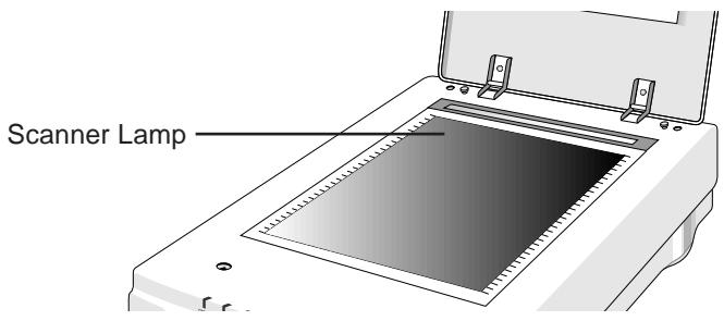
If the scanner lamp flickers, is dim, or fails to come on
The scanning lamp is failing or has failed and needs to be changed. Please contact your dealer.
7. Troubleshooting
If the Power and Ready indicators come on, but software returns “scanner link failed”, or a similar message
- Make sure the cable is connected properly.
- Check the Installation procedure to make sure you followed all of the instructions. Macintosh users should pay special attention to the setting of the SCSI ID number. PC users should pay special attention to the I/O address setting.
- Disconnect all SCSI devices and then reconnect them one by one, beginning with the scanner, to identify the device that is causing the problem.
- Check the terminators and the cables. If the cable and terminators are all properly installed, please contact your dealer.
natural_image
Diagram of an electronic device showing internal components and a magnified view of a device's internal structure (no text or symbols present)Note: If you are having intermittent problems either with the link between the scanner and your computer or are having intermittent problems with the results of your scans, try installing an external SCSI terminator.
If All Else Fails
If the above solutions do not resolve the problem, contact your dealer.
Be sure to have the following information available:
- The scanner model you are using.
- The version number of the scanner driver.
- The computer model you are using.
- All SCSI devices that you are using.
- The application software packages that you are using.
- Error codes or messages seen.
- A description of what you were doing at the time the malfunction or failure occurred.
- Other observations that may aid the technician in identifying the problem and solution.
Appendix: Specifications
| Scan Speed: | 31.2 Seconds/A4 (600 dpi, Color Mode) |
| Preview Speed: | 3.5 Seconds/A4 (Color Mode)3.5 Seconds/A4 (Gray/Line art Mode) |
| Maximum Scannable Area: |
| 216 x 297 mm (8.5 x 11.7 Inches) |
| Optical Resolution: | 600 x 1200 dpi |
| Color Scanning Method: | One pass with color CCD |
Sample Depth:
| Color Mode: | 24 Bit/Pixel Internal |
| Grayscale Mode: | 8 Bit/Pixel Internal |
| Line-Art Mode: | 1 Bit/Pixel |
Scanner Settings:
| Scaling: | 1% to 200% in 1% Increments at 600 dpi Resolution |
| Highlight/Shadow: | 255 Steps |
| Contrast/Brightness: | +100% to -100% |
| Gamma Curve: | Downloadable Curves |
| Analog Gamma: | Range 1.0 - 2.0 |
Data Output
| Color Mode: | 24 Bit (Hardware) / 24 Bit (System) |
| Grayscale Mode: | 8 Bit (Hardware) / 8 Bit (System) |
| Interface: | Built-in SCSI 2; One 25-pin Connector and One 50-pin Connector |
Power Requirements:
| Voltage: | 100 - 240V AC |
| Frequency: | 50/60 Hz |
| Power Consumption: | Maximum 60 Watts |
Environmental Ranges:
Operating Temperature: 50^ F to 95^ F ( 10^ C to 35^ C)
Relative Humidity: 10% to 85%
Dimensions: 13.3 (W) x 21.0 (D) x 5.7 (H) inches
(336 x 534.5 x 144 mm)
Net Weight: 17.4 lbs (7.9 kg)
Systems Supported: PC and Macintosh
Options: Transparency Unit (AT-20),
Auto Document Feeder (AF-10)
Index
Symbols
25-pin SCSI Connector 14
50-pin SCSI Connector 14
A
AC Inlet 14
Auto Document Feeder 1
C
Carriage Lock 14
Cleaning 30
Components 11
Connecting the Power Cord 17
Connecting the Scanner 16
Connecting the SCSI Cable 19
Connecting to the IBM PC/AT or compatible computer 20
Connecting to the Macintosh computer 20
D
Document Cover 13
H
Handling Precautions 4
|
If the Power indicator fails to come on 31
If the scanner lamp flickers, is dim, or fails to 31
Indicator Panel 13
M
Main body 11
Maintenance 29
O
optical resolution 1
Option Connector 14
P
Parts Identification 11
Power cord 12
Power Supply 2
Power Switch 14
S
scanning area 1, 26
Scanning carriage 10
scanning transparency films for OHP 26
SCSI cable 12
SCSI Chain Connection with Other Devices 21
SCSI ID Switch 14
Setting a Document 26
Setting the SCSI ID 23
Specifications 34
Static Electricity Precautions 29
Storage and Operating Locations 7
T
Terminator 12
Transparency Adapter 1
Transportation Precaution 10
Troubleshooting 31
Turning on the Power 24
U
Unlocking the Scanner 15
EC DECLARATION OF CONFORMITY
We
| Name: | Nikon UK Limited |
| Address: | Nikon House, 380 Richmond Road, Kingston, Surrey KT2 5PR, UK |
| declare that the product | |
| Product Name: | Nikon Flatbed Scanner AX-210 (ScanTouch 210) |
| Manufacturer’s Name: | Nikon Corporation |
| Manufacturer’s Address: | Fuji Bldg., 2-3, Marunouchi 3-chome, Chiyoda-ku, Tokyo 100, Japan |
| is in conformity with the following Standards | |
| EN55022 Class B | |
| EN50082-1 | |
| IEC801-2: 1984 8kV | |
| IEC801-3: 1984 3V/m | |
| IEC801-4: 1988 1kVAC, 0.5kV, I/O | |
following the provisions of the EMC Directive (89/336/EEC)
DECLARATION DE CONFORMITE DE LA CEE
Nous
- Indication
- Trademark Information
- Important Safeguard
- Federal Communications Commission (FCC) Radio Frequency Interference Statement
- CAUTION
- Modifications
- SCSI Cable
- Notice for customers in Canada
- ATTENTION
- When Taking the Unit Out of The Country
- Notice concerning prohibition of copying or reproduction
- Contents
- Overview ...... 1
- Before Operating the Scanner.... 2
- Parts Identification 11
- Connecting the Scanner 16
- Operation 24
- Maintenance....29
- Troubleshooting 31
- Overview
- Before Operating the Scanner
- Power Supply Precautions
- Handling Precautions
- Remarks
- If You Notice Anything Abnormal
- Storage and Operating Locations
- Do not store or use where:
- Transportation Precaution
- Parts Identification
- Inspection
- Components
- Main Body
- A Closer Look
- Unlocking the Scanner
- Connecting the Scanner
- Before Connection
- Connecting the Power Cord
- Connecting the SCSI Cable
- Connecting to the Macintosh computer
- Connecting to the IBM PC/AT or compatible computer
- SCSI Chain Connection with Other Devices
- Setting the SCSI ID
- Operation
- Turning on the Power
- Setting a Document
- Step 1
- Step 2
- Cautions
- Step 3
- Maintenance
- Static Electricity Precautions
- Cleaning
- Troubleshooting
- If the Power indicator fails to come on
- If the scanner lamp flickers, is dim, or fails to come on
- If the Power and Ready indicators come on, but software returns “scanner link failed”, or a similar message
- If All Else Fails
- Appendix: Specifications
- Environmental Ranges:
- Index
- Symbols
- A
- C
- D
- H
- |
- M
- O
- P
- S
- T
- U
- EC DECLARATION OF CONFORMITY
- DECLARATION DE CONFORMITE DE LA CEE
Brand : NIKON
Model : SCANTOUCH 210
Category : To scan