
XM-4080 - Audio Amplifier YAMAHA - Free user manual and instructions
Find the device manual for free XM-4080 YAMAHA in PDF.
| Product type | Audio amplifier |
| Brand | YAMAHA |
| Model | XM-4080 |
| Output power | 50 W per channel at 8 ohms (20 Hz - 20 kHz, 0.1% THD) |
| Load impedance | 4 to 8 ohms |
| Frequency response | 20 Hz - 20 kHz ±0.5 dB |
| Signal-to-noise ratio | 100 dB |
| Total harmonic distortion | < 0.05% |
| Inputs | 2 x RCA, 1 x XLR (balanced) |
| Outputs | 2 x speaker terminals, 1 x 6.35mm headphone jack |
| Power supply | 230 V ~ 50 Hz |
| Power consumption | 150 W (max) |
| Dimensions (W x H x D) | 435 x 88 x 300 mm |
| Weight | 7.5 kg |
| Main features | Volume, balance, bass/treble, input selector, standby |
| Maintenance and cleaning | Unplug the device and wipe with a soft, dry cloth. Do not use abrasive products. |
| Safety | Do not expose to moisture or heat sources. Unplug during storms. |
| Spare parts and repairability | Contact Yamaha after-sales service or an authorized center for any repairs. |
| General information | 2-year warranty. Made in Malaysia. For assistance, refer to the list of Yamaha contacts in the manual. |
Frequently Asked Questions - XM-4080 YAMAHA
User questions about XM-4080 YAMAHA
0 question about this device. Answer the ones you know or ask your own.
Ask a new question about this device
Download the instructions for your Audio Amplifier in PDF format for free! Find your manual XM-4080 - YAMAHA and take your electronic device back in hand. On this page are published all the documents necessary for the use of your device. XM-4080 by YAMAHA.
USER MANUAL XM-4080 YAMAHA
This product, when installed as indicated in the instructions contained in this manual, meets FCC requirements. Modifications not expressly approved by Yamaha may void your authority, granted by the FCC, to use the product.
2. IMPORTANT: When connecting this product to accessories and/or another product use only high quality shielded cables. Cable/s supplied with this product MUST be used. Follow all installation instructions. Failure to follow instructions could void your FCC authorization to use this product in the USA.
- This applies only to products distributed by YAMAHA CORPORATION OF AMERICA.
(oscillator)
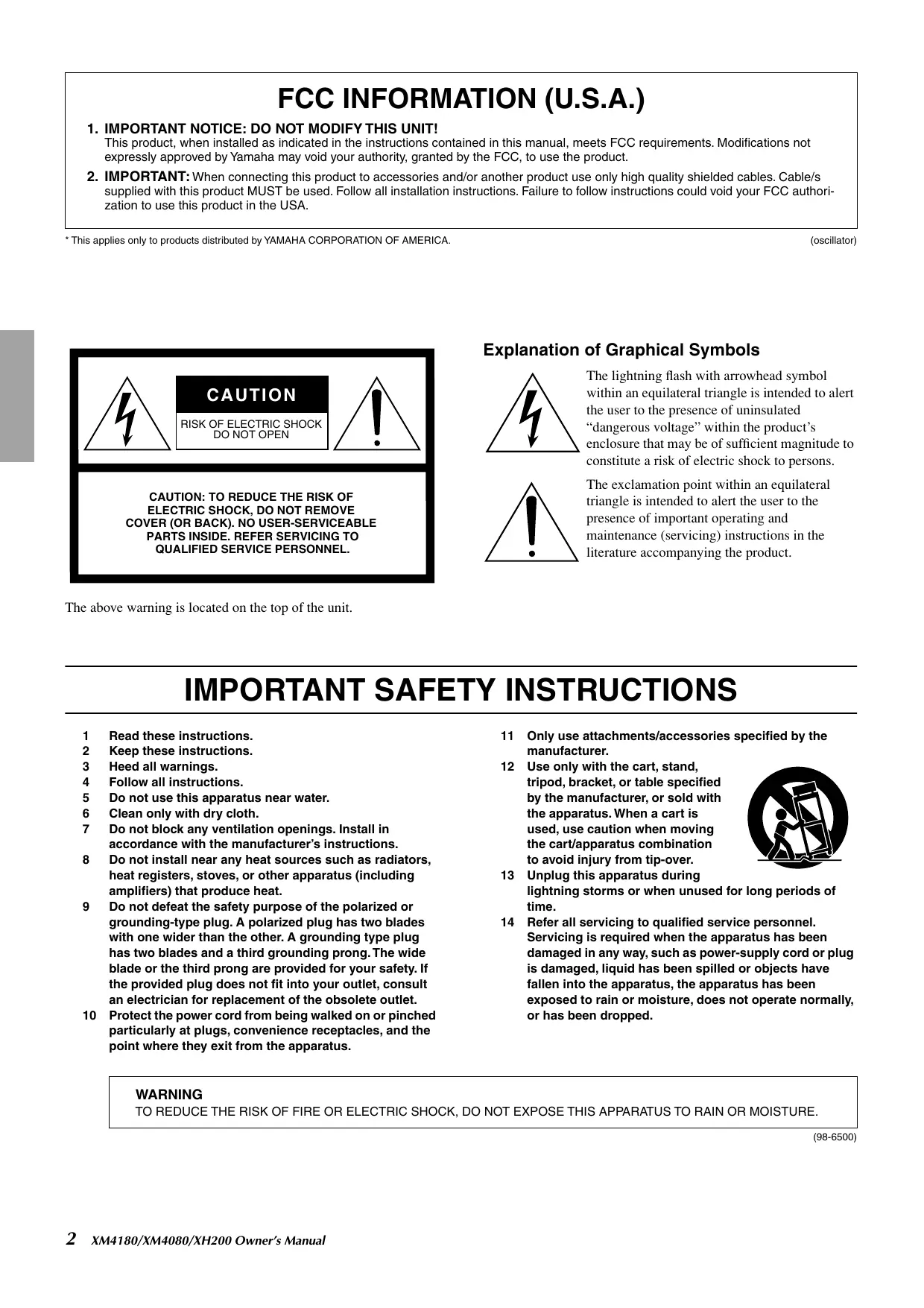
The above warning is located on the top of the unit.
Explanation of Graphical Symbols
The lightning flash with arrowhead symbol within an equilateral triangle is intended to alert the user to the presence of uninsulated "dangerous voltage" within the product's enclosure that may be of sufficient magnitude to constitute a risk of electric shock to persons.

The exclamation point within an equilateral triangle is intended to alert the user to the presence of important operating and maintenance (servicing) instructions in the literature accompanying the product.
IMPORTANT SAFETY INSTRUCTIONS
1 Read these instructions.
2 Keep these instructions.
3 Heed all warnings.
4 Follow all instructions.
5 Do not use this apparatus near water.
6 Clean only with dry cloth.
7 Do not block any ventilation openings. Install in accordance with the manufacturer's instructions.
8 Do not install near any heat sources such as radiators, heat registers, stoves, or other apparatus (including amplifiers) that produce heat.
9 Do not defeat the safety purpose of the polarized or grounding-type plug. A polarized plug has two blades with one wider than the other. A grounding type plug has two blades and a third grounding prong. The wide blade or the third prong are provided for your safety. If the provided plug does not fit into your outlet, consult an electrician for replacement of the obsolete outlet.
10 Protect the power cord from being walked on or pinched particularly at plugs, convenience receptacles, and the point where they exit from the apparatus.
11 Only use attachments/accessories specified by the manufacturer.
12 Use only with the cart, stand, tripod, bracket, or table specified by the manufacturer, or sold with the apparatus. When a cart is used, use caution when moving the cart/apparatus combination to avoid injury from tip-over.
13 Unplug this apparatus during lightning storms or when unused for long periods of time.
14 Refer all servicing to qualified service personnel. Servicing is required when the apparatus has been damaged in any way, such as power-supply cord or plug is damaged, liquid has been spilled or objects have fallen into the apparatus, the apparatus has been exposed to rain or moisture, does not operate normally, or has been dropped.
WARNING
TO REDUCE THE RISK OF FIRE OR ELECTRIC SHOCK, DO NOT EXPOSE THIS APPARATUS TO RAIN OR MOISTURE.
(98-6500)
PRECAUTIONS
PLEASE READ CAREFULLY BEFORE PROCEEDING
- Please keep this manual in a safe place for future reference.

WARNING
Always follow the basic precautions listed below to avoid the possibility of serious injury or even death from electrical shock, short-circuiting, damages, fire or other hazards. These precautions include, but are not limited to, the following:
Power supply/Power cord
- Only use the voltage specified as correct for the device. The required voltage is printed on the name plate of the device.
- Use only the included power cord.
- Do not place the power cord near heat sources such as heaters or radiators, and do not excessively bend or otherwise damage the cord, place heavy objects on it, or place it in a position where anyone could walk on, trip over, or roll anything over it.
- Be sure to connect to an appropriate outlet with a protective grounding connection. Improper grounding can result in electrical shock.
Do not open
- Do not open the device or attempt to disassemble the internal parts or modify them in any way. The device contains no user-serviceable parts. If it should appear to be malfunctioning, discontinue use immediately and have it inspected by qualified Yamaha service personnel.
Water warning
- Do not expose the device to rain, use it near water or in damp or wet conditions, or place containers on it containing liquids which might spill into any openings.
- Never insert or remove an electric plug with wet hands.
If you notice any abnormality
- If the power cord or plug becomes frayed or damaged, or if there is a sudden loss of sound during use of the device, or if any unusual smells or smoke should appear to be caused by it, immediately turn off the power switch, disconnect the electric plug from the outlet, and have the device inspected by qualified Yamaha service personnel.
- If this device should be dropped or damaged, immediately turn off the power switch, disconnect the electric plug from the outlet, and have the device inspected by qualified Yamaha service personnel.

CAUTION
Always follow the basic precautions listed below to avoid the possibility of physical injury to you or others, or damage to the device or other property. These precautions include, but are not limited to, the following:
Power supply/Power cord
- Remove the electric plug from the outlet when the device is not to be used for extended periods of time, or during electrical storms.
- When removing the electric plug from the device or an outlet, always hold the plug itself and not the cord. Pulling by the cord can damage it.
Location
- Before moving the device, remove all connected cables.
- When setting up the product, make sure that the AC outlet you are using is easily accessible. If some trouble or malfunction occurs, immediately turn off the power switch and disconnect the plug from the outlet. Even when the power switch is turned off, electricity is still flowing to the product at the minimum level. When you are not using the product for a long time, make sure to unplug the power cord from the wall AC outlet.
- Do not use the device in a confined, poorly-ventilated location. If this device is to be used in a small space other than an EIA-standard rack, make sure that there is adequate space between the device and surrounding walls or other devices: at least 5cm at the sides, 10cm behind and 10cm above. Inadequate ventilation can result in overheating, possibly causing damage to the device(s), or even fire.
- Do not expose the device to excessive dust or vibrations, or extreme cold or heat (such as in direct sunlight, near a heater, or in a car during the day) to prevent the possibility of panel disfiguration or damage to the internal components.
-
Do not place the device in an unstable position where it might accidentally fall over.
-
Do not block the vents. This device has ventilation holes at the front and rear to prevent the internal temperature from becoming too high. In particular, do not place the device on its side or upside down. Inadequate ventilation can result in overheating, possibly causing damage to the device(s), or even fire.
- Do not use the device in the vicinity of a TV, radio, stereo equipment, mobile phone, or other electric devices. Doing so may result in noise, both in the device itself and in the TV or radio next to it.
- Do not place the device in a location where it may come into contact with corrosive gases or salt air. Doing so may result in malfunction.
Connections
- Before connecting the device to other devices, turn off the power for all devices. Before turning the power on or off for all devices, set all volume levels to minimum.
- Use only speaker cables for connecting speakers to the speaker jacks. Use of other types of cables may result in fire.
- Be sure to connect to a properly grounded power source. A ground screw is provided on the rear panel of this device for maximum safety and shock prevention. If the mains outlet is not grounded, be sure to connect the ground screw to a confirmed ground point before plugging the device into the mains. Improper grounding can result in electrical shock.
Maintenance
- Remove the power plug from the AC outlet when cleaning the device.
Handling caution
- When turning on the AC power in your audio system, always turn on the device LAST, to avoid speaker damage. When turning the power off, the device should be turned off FIRST for the same reason.
- Do not insert your fingers or hands in any gaps or openings on the device (vents, etc.).
-
Avoid inserting or dropping foreign objects (paper, plastic, metal, etc.) into any gaps or openings on the device (vents, etc.) If this happens, turn off the power immediately and unplug the power cord from the AC outlet. Then have the device inspected by qualified Yamaha service personnel.
-
Do not use the device for a long period of time at a high or uncomfortable volume level, since this can cause permanent hearing loss. If you experience any hearing loss or ringing in the ears, consult a physician.
- Do not rest your weight on the device or place heavy objects on it, and avoid use excessive force on the buttons, switches or connectors.
- Do not use this device for any purpose other than driving loudspeakers.
Yamaha cannot be held responsible for damage caused by improper use or modifications to the device, or data that is lost or destroyed.
Always turn the power off when the device is not in use.
Even when the power switch is in the "STANDBY", electricity is still flowing to the device at the minimum level. When you are not using the device for a long time, make sure you unplug the power cord from the wall AC outlet.
The performance of components with moving contacts, such as switches, volume controls, and connectors, deteriorates over time. Consult qualified Yamaha service personnel about replacing defective components.
Illustrations in this manual are for explanatory purposes only, and may not match the actual appearance of the product during operation.
Company names and product names used in this Owner's Manual are trademarks or registered trademarks of their respective owners.
IMPORTANT NOTICE FOR THE UNITED KINGDOM
Connecting the Plug and Cord
WARNING: THIS APPARATUS MUST BE EARTHED
IMPORTANT. The wires in this mains lead are coloured in accordance with the following code:
GREEN-AND-YELLOW : EARTH
BLUE : NEUTRAL
BROWN : LIVE
As the colours of the wires in the mains lead of this apparatus may not correspond with the coloured markings identifying the terminals in your plug proceed as follows:
The wire which is coloured GREEN-and-YELLOW must be connected to the terminal in the plug which is marked by the letter E or by the safety earth symbol ① or colored GREEN or GREEN-and-YELLOW.
The wire which is coloured BLUE must be connected to the terminal which is marked with the letter N or coloured BLACK.
The wire which is coloured BROWN must be connected to the terminal which is marked with the letter L or coloured RED.
- This applies only to products distributed by Yamaha-Kemble Music (U.K.) Ltd. (3 wires)
This mark indicates a dangerous electrically live terminal. When connecting an external wire to this terminal, it is necessary either to have "a person who have received appropriate guidance on handling" make the connection or to use leads or a cord that have been manufactured in such a way that the connection can be made simply and without problem.
Thank you for purchasing a Yamaha XM4180, XM4080 or XH200 Power Amplifier.
These power amplifiers were developed from Yamaha's wealth of experience in building PA equipment and its tradition of careful attention to every detail of circuit design. These power amplifiers feature high power and superb quality together with superior reliability and stability, guaranteeing the highest possible audio performance.
Main features include
On the XM4180/XM4080:
- Four separate amplifier sections allows the unit to be configured in stereo mode, 2-channel parallel (mono) mode, and bridged mode.
- Balanced XLR and Euroblock connector inputs, 5-way binding post outputs.
Each A/B and C/D channel pair features a high-pass filter, with the cutoff frequency switchable between 20Hz and 55Hz.
On the XM4180:
- Enables parallel connection to multiple high-impedance speakers that support 70V line output.
On the XH200:
- Enables parallel connection to multiple high-impedance speakers that support 70V or 100V line output and a maximum output of 200 watts/channel.
- Euroblock connector inputs, barrier strip outputs, and a high-pass filter, with the cutoff frequency switchable between 40Hz and 80Hz .
On the XM4180/XM4080/XH200:
- Protection includes power on/off muting, DC detection, temperature, and protection indicator.
- Variable-speed, low-noise cooling fan system ensures high reliability even under the most demanding conditions.
- A MONITOR/REMOTE terminal, which allows control or monitoring of this amplifier from an external device.
This Owner's Manual applies to the XM4180, XM4080 and XH200 power amplifiers. In order to take full advantage of the amplifier and enjoy long and trouble-free operation, please read this Owner's Manual carefully before using the product.
Contents
Controls and Functions 6
Front Panel 6
Rear Panel (XM4180/XM4080) 7
Rear Panel (XH200) 10
Connection 11
Using a Euroblock connector 11
Speaker Connection 12
Troubleshooting 12
Specifications 13
General Specifications 13
MONITOR/REMOTE PIN layout 14
Current Draw 15
Dimensions 16
Block Diagram 17
Front Panel
* The illustration shows model XM4180.
① POWER/STANDBY switch and indicator
This is the main POWER switch. Press to turn on the amplifier. Press it again to turn off. The POWER indicator lights up when the amplifier it turned on. STANDBY operation can only be set from an external device, connected to the REMOTE terminal. When STANDBY is on, the indicator is lit in orange.
② PROTECT/MUTE indicator
When the protection system is active, the PROTECT indicator lights up and the speakers are automatically disconnected from the amplifier's outputs. The protection system activates in the following situations:
When the amplifier is turned on
The protection system activates for approximately three seconds when the amplifier is turned on. After three seconds, the protection system deactivates automatically and the amplifier is ready for normal operation.
If a DC voltage is detected at the amplifier's outputs
The protection system activates if a DC voltage is detected at the amplifier's outputs. Once the DC voltage problem is corrected, the protection system deactivates automatically and the amplifier is ready for normal operation.
If the amplifier overheats
When overheating occurs, the PROTECT/MUTE indicator lights. You should immediately turn off the amplifier and allow it time to cool down. See the Precautions section of this Owner's Manual for ways to prevent the amplifier from overheating.
③ CLIP/LIMIT indicator
A channel's CLIP indicator lights up when its output distortion exceeds 1% (i.e., clipping). Output signal clipping is typically caused by excessive input signal levels. When this happens, the limiter is engaged automatically.
④ SIGNAL indicator
A channel's SIGNAL indicator lights up when its output exceeds a certain amount (2V rms on the XM4180/ XM4080, 4V rms on the XH200.)
⑤ VOLUME controls
The channel volume controls have click detents for the settings, and each channel can be set over a range of - dB to 0dB . On the XM4180 and XM4080, when the amplifier is set to bridged mode, only the first volume control on each channel pair is used (i.e., for the A/B pair, channel A is active, and for the C/D pair, channel C is active).
⑥ Air intakes
The amplifier has a forced-air cooling fan that takes in air from the front and exhausts it from the rear. Make absolutely sure that these intakes are not obstructed.
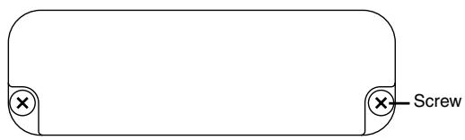
Security cover
If you want to keep the volume settings from being modified, attach the included security cover using the screw holes shown below, so that the volume controls are inaccessible.
* The illustration shows model XM4180/XM4080.
Rear Panel (XM4180/XM4080)
* The illustration shows model XM4180.
① XLR inputs connectors
These balanced XLR-3-31 type connectors are used to connect input signals.
The pins are wired as shown below (IEC 60268).
- In bridged mode, only the first channel in the pair is active; i.e., channel A of pair A/B, and channel C of pair C/D. Make sure not to input an audio signal to an inactive input terminal.
② Euroblock connectors
These balanced Euroblock connectors are used to connect input signals.
③ HPF switches
These switches are used to turn on and off the HPF (High Pass Filter) for channels A-B or C-D. When this is set to 20Hz or 55Hz , frequencies below the respective settings are filtered using a 12 dB/octave high pass filter.
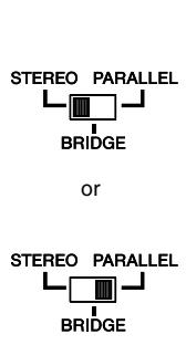
④ MODE switch
STEREO mode
In STEREO mode, channels A, B, C and D are completely independent.
PARALLEL mode
In PARALLEL mode, the channel A input signal is sent both to the channel A power amp and the channel B power amp. In this case, loads are automatically connected between the A and B input terminals. (The same applies to the C and D input terminals.)
By sending the signal from channels A/B to C/D you can use the unit as a four-channel mono amplifier.
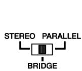
BRIDGED mode
In BRIDGED mode, channels A and B operate simultaneously, functioning as a single mono amplifier.
(The same applies to the C and D.)
Note: When in PARALLEL and BRIDGED modes, input terminals A-B and C-D are shorted automatically. Make sure not to input an audio signal to an inactive input terminal.
⑤ MONITOR/REMOTE terminals
This terminal is used to connect the external device for monitoring or remote control. Refer to "MONITOR/REMOTE PIN layout" on page 14.
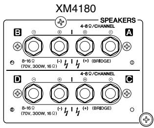
⑥ SPEAKERS terminals
These 5-way binding posts are used to connect speakers.
GND terminal
If you are having a problem with hum or noise, use this terminal to connect to ground (earth) or to connect to the chassis of a mixer, preamp, or other device in your system.
⑧ AC IN
Connect one plug of the included AC cable to this inlet. Connect the other plug of the AC cable to an AC outlet that meets the power supply conditions printed on the label at the top of the unit.
- Using as a four-channel mono amplifier with a mono input (XM4180/XM4080)
By connecting input terminals B and C with a proper cable, and setting both mode switches for A/B and C/D to PARALLEL, you can use the unit as a four-channel mono amplifier.
The volume controls on the front panel (A to D) let you control the volume of each channel independently.
Note In this case, the loads for A and B or C and D are connected in the amplifier. Make sure not to input any signal to the D terminal.
* The illustration shows model XM4180.
- Using as a two-channel amplifier with a mono input for high-power applications (XM4180/XM4080)
By connecting input terminals B and C with a proper cable, and setting both mode switches for A/B and C/D to BRIDGE, you can use the unit as a two-channel high-power mono amplifier.
Note In this case, the loads for A and B or C and D are connected in the amplifier. Make sure not to input any signal to the D terminal.
* The illustration shows model XM4180.
- Speaker connections (XM4180/XM4080)
Speakers can be connected to the amplifier in two ways, as shown below. Note that speaker impedance will vary according to the connection method and the number of speakers. Please be sure that your speaker's impedance is not less than the relevant minimum value indicated below.
Connection configurations for STEREO and PARALLEL modes
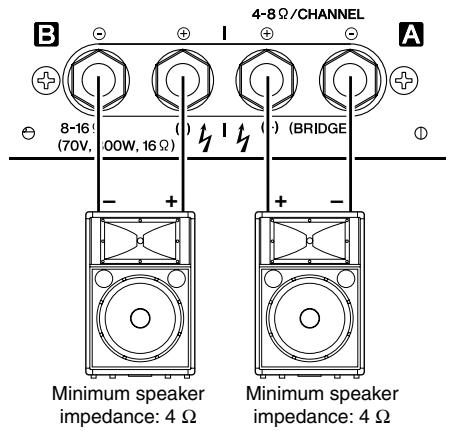
Connection configurations for BRIDGED mode
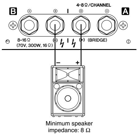
* The illustration shows model XM4180.
When connecting high-impedance speakers in parallel (XM4180 only)
XM4180 enables you to connect in parallel fashion multiple high-impedance speakers that support 70V line output. The number of speakers that can be connected varies depending on the rated input of the speakers. The XM4180 can be connected to speakers with a total rated input of up to 300 W. For example, if you connect ten speakers with a rated input of 5 W (50 W), ten speakers with a rated input of 10 W (100 W) and ten speakers with a rated input of 15 W (150 W), the amplifier can be used with a total rated speaker input of 300 W as shown below:
CAUTION
Be sure to use speakers that support the XM4180's line-out voltage of 70 V.
* The illustration shows model XM4180.
Rear Panel (XH200)
① Euroblock connectors
These balanced Euroblock connectors are used to connect input signals.
② HPF switches
These switches are used to set the cutoff frequency of the HPF (High Pass Filter) for each channel. Frequencies below 40Hz or 80Hz are filtered using a 12dB octave high pass filter.
- When the amplifier is set to 40Hz , make sure that the speaker transformer is capable of sufficiently handling low frequency signals.
CAUTION
Be careful when inputting low frequency signals; excessive levels at low frequencies may cause damage to the speaker, speaker transformer or to the amplifier itself.
③ Output voltage switch
This switch is used to change the output voltage between 70V and 100V.
④ MONITOR/REMOTE terminals
This terminal is used to connect the external device for monitoring or remote control. Refer to "MONITOR/REMOTE PIN layout" on page 14.
⑤ SPEAKERS terminals
This unit includes barrier strip terminals, which are wired as shown below.
Hot ,Cold
Refer to "Speaker connections (XH200)" on page 10 for more information on the impedance of speaker systems that can be connected to these terminals.
GND terminal
If you are having a problem with hum or noise, use this terminal to connect to ground (earth) or to connect to the chassis of a mixer, preamp, or other device in your system.
⑦ AC IN
- Connect one plug of the included AC cable to this inlet.
- Connect the other plug of the AC cable to an AC outlet that meets the power supply conditions printed on the label at the top of the unit.
Speaker connections (XH200)
The XH200 enables you to connect in parallel fashion multiple high-impedance speakers that support 70V or 100V line output. The number of speakers that can be connected varies depending on the speaker's rated input. You can connect speakers with a total rated input per channel of up to 200 W.
For example, if you are using speakers with a rated input of 10W , you can connect up to twenty speakers. If you are using speakers with a rated input of 20W , you can connect up to ten speakers
You may also connect speakers with different rated inputs to different channels or connect speakers with different rated input to the same channel, as shown below:
Total rated input of speakers : 200W
CAUTION
Be sure to use speakers that support the XH200's line-out voltage of 70V or 100V.
CAUTION
You cannot connect a low-impedance speaker directly to the XH200. In this case, be sure to use a speaker transformer (such as the Yamaha ST15). Follow the instruction guide that came with the speaker transformer to avoid excessive loads.
Using a Euroblock connector
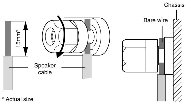
Cable preparation
- To prepare the cable for attachment to a Euroblock connector, strip the wire as shown in the illustration, and use stranded wire to make connections. With a Euroblock connection, the stranded wire may be prone to breakage because of metal fatigue due to the weight of the cable or due to vibration. When rack-mounting your equipment, use a lacing bar when possible to bundle and fasten the cables.
- If cables will be frequently connected and disconnected, as in the case of a portable installation, we recommend that you use ferrules with insulation sleeves. Use a ferrule whose conductor portion has an external diameter of 1.6 mm or less, and a length of approximately 7 mm (such as the AI0, 5-6WH made by the Phoenix Contact corporation).
CAUTION
If you use stranded wire, do not tin (plate with solder) the exposed end.
1 If the wire insertion ports are closed, turn the screws on top of the connector counterclockwise to open the ports.
2 Insert the wires into the appropriate ports, following the indication of the pole on the input terminal, turn the screws on top of the connector clockwise to fix the wires.
3 Attach the Euroblock connector to the input terminal on the unit.
Speaker Connection
1 Turn off the POWER switch.
2 Remove the cover attachment screws and remove the protective cover from the speaker terminals.
3 Remove about 15mm of insulation from the end of each speaker cable.
4 When using 5-way binding posts (XM4180, XM4080) Pass the bare wire through the holes in the appropriate speaker terminals. Tighten the terminals to securely clamp the wires. Refer to 9 page for speaker polarities. Be sure that the bare wire ends do not jut out from the terminals and touch the chassis.
When using barrier strip terminals (XH200)
Wrap the wire around the terminal as shown in the illustration, and tighten the screw to securely clamp the wire. Refer to 10 page for speaker polarities.
Be sure that the bare wire ends do not jut out from the terminal and touch the chassis.
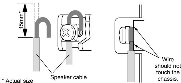
5 Reattach the protective cover over the speaker terminals.
Troubleshooting
The following table lists the main causes of abnormal operation and the corrective measures required as well as the protective circuit operation in each case.
| Indicator | Possible Cause | Remedy | Protection Circuit |
| CLIP/LIMIT indicator lights up | There is a short at the amplifier's speaker outputs, the speaker's inputs, or in the wiring. | Locate and remove the short. | The PC limiter circuit activates to protect the power transistors. |
| The impedance of the connected speaker is too low. | Check the impedance rating of the connected speaker and make sure that it conforms to the impedance indicated at the speaker terminals on the amplifier. | ||
| PROTECT/MUTE indicator lights up | The temperature of amplifier is too high. | Let the amplifier cool and check that ventilation around the amplifier is appropriate for operation, as suggested in the Precautions section. | The thermal protection circuit activates to protect the power transistors. |
| A DC voltage of ±2 V or greater was detected in the amplifier's output circuit. | Consult your dealer or a Yamaha service center. | The output relay activates to protect the speaker system. |
General Specifications
- XM4180/XM4080
| XM4180 | XM4080 | ||||
| Output Power* | 1 kHz, THD+N= 1 % | 8 Ω/Channel | MIN | 210 W x 4 | 90 W x 4 |
| 4 Ω/Channel | 250 W x 4 | 120 W x 4 | |||
| 8 Ω/Bridged | 500 W x 2 | 240 W x 2 | |||
| 20 Hz-20 kHzTHD+N= 0.1 % | 8 Ω/Channel | 180 W x 4 | 80 W x 4 | ||
| 4 Ω/Channel | 230 W x 4 | 115W x 4 | |||
| 8 Ω/Bridged | 460 W x 2 | 230W x 2 | |||
| 70 V/Bridged RL=16 Ω | 300 W x 2 | - | |||
| Voltage Gain | Att. max | TYP | 30 dB | 26 dB | |
| Power Consumption | Standby | TYP | 5 W | 5 W | |
| Idle | TYP | 40 W | 40 W | ||
| 1/8 (4 Ω/Pink noise) | TYP | 600 W | 400 W | ||
| THD+N | 20 Hz-20 kHz, Half Power | MAX | 0.1 % | ||
| Intermodulation Distortion | 60 Hz:7 kHz, 4:1, Half Power | MAX | 0.1 % | ||
| Frequency Response | RL=8 Ω, Po=1 W, HPF=OFF,20 Hz-20 kHz | MAX | 0 dB | ||
| TYP | 0 dB | ||||
| MIN | -0.5 dB | ||||
| SN Ratio | (DIN AUDIO) | MIN | 103 dB | ||
| Channel Separation | Half Power, RL=8 Ω, 1 kHzAtt. max, input 600 Ω shunt | MIN | 60 dB | ||
| Residual Noise | Att. min, (DIN AUDIO) | MAX | -73 dBu | ||
| Damping Factor | RL=8 Ω, 1kHz | MIN | 100 | ||
| Input Sensitivity | RL=8 Ω, Att. max | TYP | +4 dBu | ||
| Maximum Input Voltage | MIN | +22 dBu | |||
| Input Impedance | TYP | 20 kΩ (balanced), 10 kΩ (unbalanced) | |||
| Controls | Front Panel | POWER switch (push on/push off)attenuator (31 position) x 4 | |||
| Rear Panel | MODE switch (STEREO/BRIDGE/PARALLEL) x 2HPF switch (20 Hz/55 Hz/OFF 12 dB/oct) x 2 | ||||
| Connectors | INPUT | XLR-3-31 type/chEuroblock connector (balanced) /ch | |||
| SPEAKERS | 5 way binding post/ch | ||||
| MONITOR/REMOTE | Dsub 15P x 1 | ||||
| Indicators | POWER/STANDBY | x 1 (Green/Orange) | |||
| SIGNAL | x 4 (Green) | ||||
| CLIP/LIMIT | x 4 (Red) | ||||
| PROTECT/MUTE | x 4 (Red) | ||||
| Load Protection | POWER switch on/off mute | ||||
| DC-fault:output relay off/restored automatically. | |||||
| Clip limiting : THD ≥ 0.5 % | |||||
| Amplifier Protection | Thermal: Cuts the output (when heatsink temp. ≥ 90 °C);operation restored automatically. | ||||
| VI limiter (RL ≤ 2 Ω): Limits the output. | |||||
| Power Supply Protection | Thermal: Power supply shutdown (when temp. ≥ 90 °C);operation not restored automatically. | ||||
| Cooling | Variable-speed fan x 1 | ||||
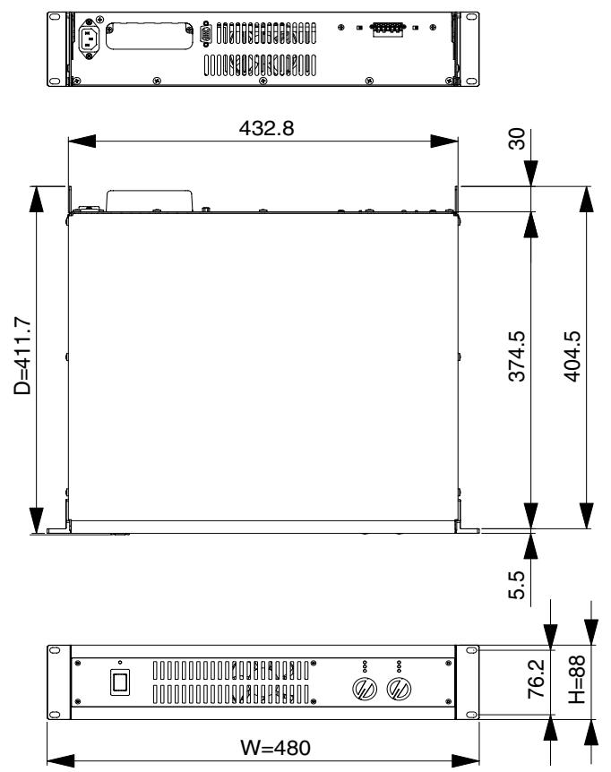
| Dimensions (W x H x D) | 480 x 88 x 412 mm | ||||
| Weight | 10 kg | 9.8 kg | |||
| Included Accessories | Power cord, Security cover, Owner's Manual,3-pin Euroblock connector x 4 | ||||
- These specifications apply to rated power supplies of 120V, 230V and 240V.
0 dBu=0.775 Vrms, Half Power=1/2 Output Power (3 dB below rated power)
Specifications and descriptions in this owner's manual are for information purposes only.
Yamaha Corp. reserves the right to change or modify products or specifications at any time without prior notice. Since specifications, equipment or options may not be the same in every locale, please check with your Yamaha dealer.
European models
Purchaser/User Information specified in EN55103-1 and EN55103-2.
Inrush Current: 25A
Conforms to Environments: E1, E2, E3 and E4
XH200
| Output Power* | 40 Hz-20 kHzTHD+N= 0.1 % | 70 V, RL=25 Ω | MIN | 200 W x 2 |
| 100 V, RL=50 Ω | 200 W x 2 | |||
| Power Consumption | Standby | 5 W | ||
| Idle | 40 W | |||
| 1/8 (70 V, RL=25 Ω/Pink noise) | 400 W | |||
| THD+N | 40 Hz-20 kHz, Half Power | MAX | 0.1 % | |
| Intermodulation Distortion | 60 Hz:7 kHz, 4:1, Half Power | MAX | 0.1 % | |
| Frequency Response | Po=1 W, HPF=40 Hz,80 Hz-20 kHz | MAX | 0 dB | |
| TYP | 0 dB | |||
| MIN | -0.5 dB | |||
| SN Ratio | (DIN AUDIO) | MIN | 103 dB | |
| Channel Separation | Half Power, 1 kHz, Att. max, input 600 Ω shunt | MIN | 60 dB | |
| Residual Noise | Att. min, (DIN AUDIO) | MAX | -65 dBu | |
| Input Sensitivity | Att. max | TYP | +4 dBu | |
| Voltage Gain | Att. max | TYP | 38 dB (100 V), 35 dB (70 V) | |
| Maximum Input Voltage | MIN | +22 dBu | ||
| Input Impedance | TYP | 20 kΩ (balanced), 10 kΩ (unbalanced) | ||
| Controls | Front Panel | POWER switch (push on/push off)attenuator (31 position) x 2 | ||
| Rear Panel | OUTPUT VOLTAGE switch (100 V/70 V) x 1HPF switch (40 Hz/80 Hz 12 dB/oct) x 2 | |||
| Connectors | INPUT | Euroblock connector (balanced) /ch | ||
| SPEAKERS | Barrier strip/ch | |||
| MONITOR/REMOTE | Dsub 15P x 1 | |||
| Indicators | POWER/STANDBY | x 1 (Green/Orange) | ||
| SIGNAL | x 2 (Green) | |||
| CLIP/LIMIT | x 2 (Red) | |||
| PROTECT/MUTE | x 1 (Red) | |||
| Load Protection | POWER switch on/off mute | |||
| DC-fault: output relay off/restored automatically. | ||||
| Clip limiting : THD ≥ 0.5 % | ||||
| Amplifier Protection | Thermal: Cuts the output (when heatsink temp. ≥ 90 °C);operation restored automatically. | |||
| VI limiter (RL ≤ 16 Ω): Limits the output. | ||||
| Power Supply Protection | Thermal: Power supply shutdown (when temp. ≥ 90 °C);operation not restored automatically. | |||
| Cooling | Variable-speed fan x 1 | |||
| Dimensions (W x H x D) | 480 x 88 x 412 mm | |||
| Weight | 9.8 kg | |||
| Included Accessories | Power cord, Security cover, Owner's Manual,3-pin Euroblock connector x 2 | |||
- These specifications apply to rated power supplies of 120V, 230V and 240V.
0 dBu=0.775 Vrms, Half Power=1/2 Output Power (3 dB below rated power)
Specifications and descriptions in this owner's manual are for information purposes only.
Yamaha Corp. reserves the right to change or modify products or specifications at any time without prior notice. Since specifications, equipment or
options may not be the same in every locale, please check with your Yamaha dealer.
■ MONITOR/REMOTE PIN layout
| Pin No. | Signal | Description | ||
| XM4180/XM4080 | XH200 | |||
| 1 | GND | |||
| 2 | REMOTE CONTROL | STANDBY | STANDBY | STANDBY Control: Supply 5 VDC, 5 mADC |
| 3 | MONITOR | MODEL ID | MODEL ID | XM4180: 560 Ω, XM4080: 680 Ω, XH200: 820 Ω (Impedance to GND) |
| 4 | REMOTE CONTROL | MUTE CH D | - | MUTE Control: Connect to GND, +5 V, 1 mA |
| 5 | MUTE CH C | MUTE CH B | ||
| 6 | MUTE CH B | - | ||
| 7 | MUTE CH A | MUTE CH A | ||
| 8 | MONITOR | PROTECT STATUS CH D | - | PROTECTION Off/ Output On: +5 VDC, Zo=270 Ω |
| 9 | PROTECT STATUS CH C | PROTECT STATUS CH B | PROTECTION On/ Output Off: 0 VDC, Zo=High | |
| 10 | PROTECT STATUS CH B | - | ||
| 11 | PROTECT STATUS CH A | PROTECT STATUS CH A | ||
| 12 | OUTPUT LEVEL CH D | - | XM4180, XM4080 | |
| 13 | OUTPUT LEVEL CH C | OUTPUT LEVEL CH B | +4dBu (-27.2 dB of Speaker Output Level) at 100 W/8Ω, RL=7.5 kΩ, Zo=300 Ω | |
| 14 | OUTPUT LEVEL CH B | - | XH200 | |
| 15 | OUTPUT LEVEL CH A | OUTPUT LEVEL CH A | -33.2 dB of Speaker Output Level, RL=7.5 kΩ, Zo=300 Ω | |
European models
Purchaser/User Information specified in EN55103-1 and EN55103-2.
Inrush Current: 25A
Conforms to Environments: E1, E2, E3 and E4
Current Draw
XM4180
| Line Current (A) | Power (W) | Thermal Dissipation | ||||||
| 100/120V | 230/240V | In | Out | Dissipated | Btu/h | kcal/h | ||
| standby | 0.08 | 0.04 | 5 | 0 | 5 | 17 | 4 | |
| idle | 1.0 | 0.5 | 40 | 0 | 40 | 137 | 34 | |
| 1/8 power | 8Ω/ch | 4.8 | 2.6 | 327 | 90 | 237 | 810 | 204 |
| 4Ω/ch | 6.8 | 3.7 | 460 | 115 | 345 | 1180 | 297 | |
| 1/3 power | 8Ω/ch | 11.3 | 6.2 | 793 | 240 | 553 | 1890 | 476 |
| 4Ω/ch | 15.9 | 8.8 | 1115 | 307 | 808 | 2760 | 695 | |
XM4080
| Line Current (A) | Power (W) | Thermal Dissipation | ||||||
| 100/120V | 230/240V | In | Out | Dissipated | Btu/h | kcal/h | ||
| standby | 0.08 | 0.04 | 5 | 0 | 5 | 17 | 4 | |
| idle | 1.0 | 0.5 | 40 | 0 | 40 | 137 | 34 | |
| 1/8 power | 8Ω/ch | 2.8 | 1.5 | 191 | 40 | 151 | 517 | 130 |
| 4Ω/ch | 4.5 | 2.4 | 303 | 58 | 245 | 837 | 211 | |
| 1/3 power | 8Ω/ch | 6.8 | 3.7 | 464 | 107 | 357 | 1220 | 307 |
| 4Ω/ch | 10.5 | 5.8 | 734 | 153 | 580 | 1980 | 499 | |
XH200
| Line Current (A) | Power (W) | Thermal Dissipation | |||||
| 100/120V | 230/240V | In | Out | Dissipated | Btu/h | kcal/h | |
| standby | 0.08 | 0.04 | 5 | 0 | 5 | 17 | 4 |
| idle | 1.0 | 0.5 | 40 | 0 | 40 | 137 | 34 |
| 1/8 power | 3.7 | 2.0 | 250 | 50 | 200 | 683 | 172 |
1/8 power is typical of program material with occasional clipping. Refer to these figures for most applications.
1/3 power represents program material with extremely heavy clipping.
Test signal: Pink Noise, bandwidth limited from 22Hz to 22kHz
[ 1\mathrm{W} = 0.860\mathrm{kcal / h}, \quad 1\mathrm{BTU} = 0.252\mathrm{kcal} ]
Note that Line Voltage [V] × Line Current [A] = [VA] , not equals to [W].
Inrush current: 11A (100V), 13A (120V), 25A (240V)
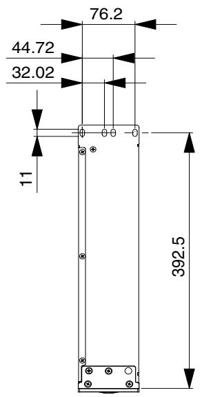
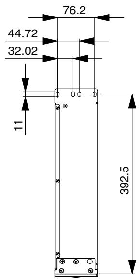
Dimensions
Unit: mm
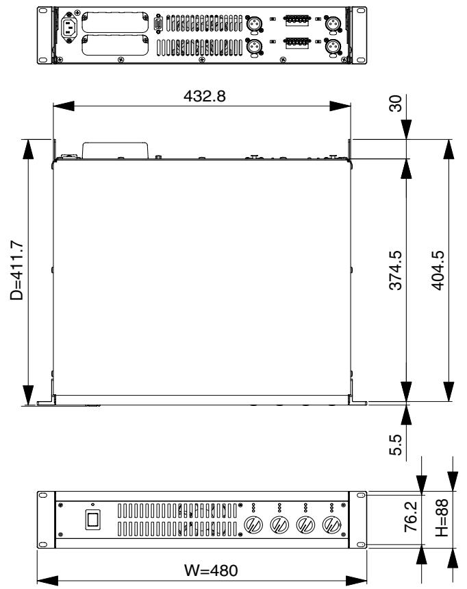
XM4180/XM4080
XH200
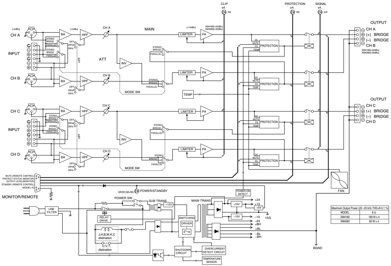
■ Block Diagram
- XM4180/XM4080
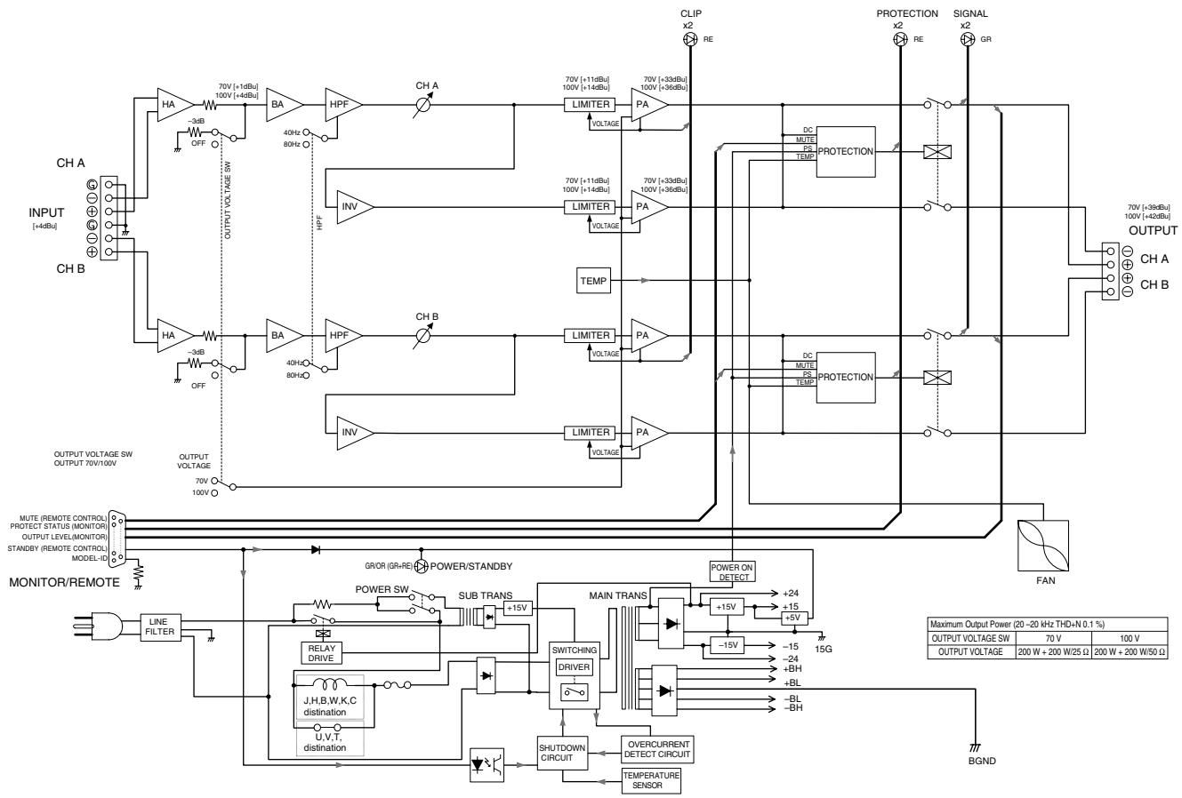
XH200
For details of products, please contact your nearest Yamaha representative or the authorized distributor listed below.
Yamaha Canada Music Ltd.
135 Milner Avenue, Scarborough, Ontario,
M1S 3R1, Canada
Tel: 416-298-1311
U.S.A.
Yamaha Corporation of America
6600 Orangethorpe Ave., Buena Park, Calif. 90620,
U.S.A.
Tel: 714-522-9011
CENTRAL & SOUTH AMERICA
MEXICO
Yamaha de Mexico S.A. de C.V.
Calz. Javier Rojo Gomez #1149,
Col. Guadalupe del Moral
C.P.09300, Mexico,D.F.,Mexico
Tel: 55-5804-0600
BRAZIL
Yamaha Musical do Brasil Ltda.
Rua Joaquim Floriano, 913 - 4' andar, Itaim Bibi,
CEP 04534-013 Sao Paulo, SP. BRAZIL
Tel: 011-3704-1377
ARGENTINA
Yamaha Music Latin America, S.A.
Sucursal de Argentina
Olga Cossettini 1553, Piso 4 Norte
Madero Este-C1107CEK
Buenos Aires, Arge
Tel: 011-4119-7000
PANAMA AND OTHER LATIN
AMERICAN COUNTRIES/
CARIBBEAN COUNTRIES
Yamaha Music Latin America, S.A.
Torre Banco General, Piso 7, Urbanizacion Marbella,
Calle 47 y Aquilino de la Guardia,
Ciudad de Panamá, Panama
Tel: +507-269-5311
EUROPE
THE UNITED KINGDOM
Yamaha Music U.K. Ltd.
Sherbourne Drive, Tilbrook, Milton Keynes,
MK7 8BL, England
Tel: 01908-366700
GERMANY
Yamaha Music Europe GmbH
Siemensstraße 22-34, 25462 Rellingen, Germany
Tel: 04101-3030
Yamaha Music Europe GmbH
Branch Switzerland in Zurich
Seefeldstrasse 94, 8008 Zürich, Switzerland
Tel: 01-383 3990
AUSTRIA
Yamaha Music Europe GmbH Branch Austria
Schleiergasse 20, A-1100 Wien, Austria
Tel: 01-60203900
CZECH REPUBLIC/SLOVAKIA/
HUNGARY/SLOVENIA
Yamaha Music Europe GmbH Branch Austria
Schleiergasse 20, A-1100 Wien, Austria
Tel: 01-602039025
POLAND
YS Copenhagen Liaison Office
Generatorvej 6A, DK-2730 Herlev, Denmark
Tel: 44 92 49 00
NORWAY
Yamaha Music (Russia)
Office 4015, entrance 2, 21/5 Kuznetskii
Most street, Moscow, 107996, Russia
Tel: 495 626 0660
OTHER EUROPEAN COUNTRIES
Yamaha Music Europe GmbH
Siemensstraße 22-34, 25462 Rellingen, Germany
Tel: +49-4101-3030
AFRICA
Yamaha Corporation,
Asia-Pacific Music Marketing Group
Nakazawa-cho 10-1, Naka-ku, Hamamatsu,
Japan 430-8650
Tel: +81-53-460-2313
MIDDLE EAST
TURKEY/CYPRUS
Yamaha Music Europe GmbH
Siemensstraße 22-34, 25462 Rellingen, Germany
Tel: 04101-3030
OTHER COUNTRIES
Yamaha Music Gulf FZE
LOB 16-513, P.O.Box 17328, Jubei Ali,
Dubai, United Arab Er
Tel: +971-4-881-5868
ASIA
THE PEOPLE'S REPUBLIC OF CHINA
Yamaha Music & Electronics (China) Co.,Ltd.
2F, Yunhedasha, 1818 Xinzha-lu, Jingan-qu,
Shanghai, China
Tel: 021-6247-2211
INDIA
Yamaha Music India Pvt. Ltd.
5F Ambience Corporate Tower Ambience Mall Complex Ambience Island, NH-8, Gurgaon-122001, Haryana, India Tel: 0124-466-5551
INDONESIA
PT. Yamaha Music Indonesia (Distributor)
PT. Nusantik
Gedung Yamaha Music Center, Jalan Jend. Gatot
SubROTO Kav. 4, Jakarta 12930, Indonesia
Tel: 21-520-2577
KOREA
Yamaha Music Korea Ltd.
8F, 9F, Dongsung Bldg. 158-9 Samsung-Dong,
Kangnam-Gu, Seoul, Korea
Tel: 080-004-0022
MALAYSIA
Yamaha Music Malaysia, Sdn., Bhd.
Lot 8, Jalan Perbandaran, 47301 Kelana Jaya,
Petaling Jaya, Selangor, Malaysia
Tel: 3-78030900
SINGAPORE
Yamaha Music Asia Pte., Ltd.
03-11 A-Z Building
140 Paya Lebor Road, Singapore 409015
Tel: 747-4374
TAIWAN
Yamaha KHS Music Co., Ltd.
3F, #6, Sec.2, Nan Jing E. Rd. Taipei.
Taiwan 104, R.O.C.
Tel: 02-2511-8688
THAILAND
Siam Music Yamaha Co., Ltd.
4, 6, 15 and 16^th floor, Siam Motors Building,
891/1 Rama 1 Road, Wangmai
Pathumwan, Bangkok 10330, Thailand
Tel: 02-215-2626
OTHER ASIAN COUNTRIES
Yamaha Corporation,
Asia-Pacific Music Marketing Group
Nakazawa-cho 10-1, Naka-ku, Hamamatsu,
Japan 430-8650
Tel: +81-53-460-2317
OCEANIA
AUSTRALIA
Yamaha Music Australia Pty. Ltd.
Level 1, 99 Queensbridge Street, Southbank,
Victoria 3006, Australia
Tel: 3-9693-5111
COUNTRIES AND TRUST
TERRITORIES IN PACIFIC OCEAN
Yamaha Corporation,
Asia-Pacific Music Marketing Group
Nakazawa-cho 10-1, Naka-ku, Hamamatsu,
Japan 430-8650
Tel: +81-53-460-2313
- Explanation of Graphical Symbols
- IMPORTANT SAFETY INSTRUCTIONS
- PRECAUTIONS
- PLEASE READ CAREFULLY BEFORE PROCEEDING
- WARNING
- Power supply/Power cord
- Do not open
- Water warning
- If you notice any abnormality
- CAUTION
- Location
- Connections
- Maintenance
- Handling caution
- IMPORTANT NOTICE FOR THE UNITED KINGDOM
- Connecting the Plug and Cord
- Main features include
- On the XM4180/XM4080:
- On the XM4180:
- On the XH200:
- On the XM4180/XM4080/XH200:
- Contents
- Front Panel
- ① POWER/STANDBY switch and indicator
- ② PROTECT/MUTE indicator
- When the amplifier is turned on
- If a DC voltage is detected at the amplifier's outputs
- If the amplifier overheats
- ③ CLIP/LIMIT indicator
- ④ SIGNAL indicator
- ⑤ VOLUME controls
- ⑥ Air intakes
- Security cover
- Rear Panel (XM4180/XM4080)
- ① XLR inputs connectors
- ② Euroblock connectors
- ③ HPF switches
- ④ MODE switch
- STEREO mode
- PARALLEL mode
- BRIDGED mode
- ⑤ MONITOR/REMOTE terminals
- ⑥ SPEAKERS terminals
- GND terminal
- ⑧ AC IN
- - Using as a four-channel mono amplifier with a mono input (XM4180/XM4080)
- - Using as a two-channel amplifier with a mono input for high-power applications (XM4180/XM4080)
- - Speaker connections (XM4180/XM4080)
- Connection configurations for STEREO and PARALLEL modes
- Connection configurations for BRIDGED mode
- When connecting high-impedance speakers in parallel (XM4180 only)
- Rear Panel (XH200)
- ① Euroblock connectors
- ② HPF switches
- ③ Output voltage switch
- ④ MONITOR/REMOTE terminals
- ⑤ SPEAKERS terminals
- ⑦ AC IN
- Speaker connections (XH200)
- Using a Euroblock connector
- Cable preparation
- Speaker Connection
- When using barrier strip terminals (XH200)
- Troubleshooting
- General Specifications
- - XM4180/XM4080
- Current Draw
- Dimensions
- ■ Block Diagram
- U.S.A.
- CENTRAL & SOUTH AMERICA
- MEXICO
- BRAZIL
- ARGENTINA
- PANAMA AND OTHER LATIN
- AMERICAN COUNTRIES/
- CARIBBEAN COUNTRIES
- EUROPE
- THE UNITED KINGDOM
- GERMANY
- AUSTRIA
- CZECH REPUBLIC/SLOVAKIA/
- HUNGARY/SLOVENIA
- POLAND
- NORWAY
- OTHER EUROPEAN COUNTRIES
- AFRICA
- MIDDLE EAST
- TURKEY/CYPRUS
- OTHER COUNTRIES
- ASIA
- THE PEOPLE'S REPUBLIC OF CHINA
- INDIA
- INDONESIA
- KOREA
- MALAYSIA
- SINGAPORE
- TAIWAN
- THAILAND
- OTHER ASIAN COUNTRIES
- OCEANIA
- AUSTRALIA
- COUNTRIES AND TRUST
- TERRITORIES IN PACIFIC OCEAN
Brand : YAMAHA
Model : XM-4080
Category : Audio Amplifier