LT903P - Video camera LG - Free user manual and instructions
Find the device manual for free LT903P LG in PDF.

| Product Type | Video Camera |
| Brand | LG |
| Model | LT903P |
| Dimensions (Approx.) | 4.7 x 2.8 x 2.4 in (120 x 70 x 60 mm) |
| Weight | 10.6 oz (300 g) including battery |
| Power Source | Rechargeable Li-ion battery (7.2 V, 1230 mAh) |
| Recording Media | Internal flash memory (16 GB) and SD/SDHC card slot |
| Video Resolution | Full HD 1920 x 1080 (60 fps) |
| Lens | 10x optical zoom, F1.8 – 2.8, 35mm equivalent: 35 – 350 mm |
| Image Stabilization | Optical image stabilization |
| Display | 3.0-inch LCD touchscreen (230K dots) |
| Focus | Auto focus and manual focus |
| Exposure | Auto, program AE, manual, various scene modes |
| Connectivity | USB 2.0, HDMI (micro), AV output |
| Wireless | Built-in Wi-Fi for remote control and file transfer |
| Microphone | Built-in stereo microphone |
| Speaker | Built-in monaural speaker |
| Battery Life (Approx.) | 2 hours continuous recording |
| Maintenance & Cleaning | Clean lens with soft microfiber cloth; keep away from dust and moisture |
| Safety Precautions | Do not disassemble, avoid extreme temperatures, use only LG chargers |
| Spare Parts & Repairability | Battery pack, AC adapter, remote control, HDMI cable; average repairability, contact LG service |
| General Information | Warranty 1 year, user manual available online, support via LG website |
Frequently Asked Questions - LT903P LG
User questions about LT903P LG
0 question about this device. Answer the ones you know or ask your own.
Ask a new question about this device
Download the instructions for your Video camera in PDF format for free! Find your manual LT903P - LG and take your electronic device back in hand. On this page are published all the documents necessary for the use of your device. LT903P by LG.
USER MANUAL LT903P LG
Dome Camera Owner's Manual
MODEL: LT903
Before installing and using the camera, please read this owner's manual carefully and retain for future reference.


CAUTION
RISK OF ELECTRIC SHOCK DO NOT OPEN

CAUTION: TO REDUCE THE RISK OF ELECTRIC SHOCK
DO NOT REMOVE COVER (OR BACK) NO USER-SERVICEABLE PARTS INSIDE REFER SERVICING TO QUALIFIED SERVICE PERSONNEL.

This lightning flash with arrowhead symbol within an equilateral triangle is intended to alert the user to the presence of uninsulated dangerous voltage within the product's enclosure that may be of sufficient magnitude to constitute a risk of electric shock to persons.

The exclamation point within an equilateral triangle is intended to alert the user to the presence of important operating and maintenance (servicing) instructions in the literature accompanying the product.
FCC WARNING : This equipment may generate or use radio frequency energy. Changes or modifications to this equipment may cause harmful interference unless the modifications are expressly approved in the instruction manual. The user could lose the authority to operate this equipment if an unauthorized change or modification is made.
REGULATORY INFORMATION: FCC Part 15
This equipment has been tested and found to comply with the limits for a Class A digital device, pursuant to Part 15 of the FCC Rules. These limits are designed to provide reasonable protection against harmful interference when the equipment is operated in a commercial environment.
This equipment generates, uses, and can radiate radio frequency energy and, if not installed and used in accordance with the instruction manual, may cause harmful interference to radio communications.
Operation of this equipment in a residential area is likely to cause harmful interference in which case the user will be required to correct the interference at his own expense.
- A suitable conduit entries, knock-outs or glands shall be provided in the cable entries of this product in the end user.
- Caution: Danger of explosion if battery is incorrectly replaced. Replaced only with the same or equivalent type recommended by the manufacturer. Dispose of used batteries according to the manufacturer's instructions.
- Holes in metal, through which insulated wires pass, shall have smooth well rounded surfaces or shall be provided with brushings.
Warning: Do not install this equipment in a confined space such as a bookcase or similar unit.
Warning: Wiring methods shall be in accordance with the National Electric Code, ANSI/NFPA 70.
Warning: This is a class A product. In a domestic environment this product may cause radio interference in which case the user may be required to take adequate measures.
Warning: To reduce a risk of fire or electric shock, do not expose this product to rain or moisture.
Caution: This installation should be made by a qualified service person and should conform to all local codes.
Caution: To avoid electrical shock, do not open the cabinet. Refer servicing to qualified personnel only.
Caution: The apparatus shall not be exposed to water (dripping or splashing) and no objects filled with liquids, such as vases, shall be placed on the apparatus.

Disposal of your old appliance
- When this crossed-out wheeled bin symbol is attached to a product it means the product is covered by the European Directive 2002/96/EC.
- All electrical and electronic products should be disposed of separately from the municipal waste stream via designated collection facilities appointed by the government or the local authorities.
- The correct disposal of your old appliance will help prevent potential negative consequences for the environment and human health.
- For more detailed information about disposal of your old appliance, please contact your city office, waste disposal service or the shop where you purchased the product.
CE
This product is manufactured to comply with EMC Directive 2004/108/EC and Low Voltage Directive 2006/95/EC.
European representative:
LG Electronics Service Europe B.V. Veluwezoom 15, 1327 AE Almere, The Netherlands
(Tel : +31-036-547-8940)
Important Safety Instructions
- Read these instructions.
- Keep these instructions.
- Heed all warnings.
- Follow all instructions.
- Do not use this apparatus near water.
- Clean only with dry cloth.
- Do not block any ventilation openings. Install in accordance with the manufacturer's instructions.
- Do not install near any heat sources such as radiators, heat registers, stoves, or other apparatus (including amplifiers) that produce heat.
- Do not defeat the safety purpose of the polarized or grounding-type plug. A polarized plug has two blades with one wider than the other. A grounding type plug has two blades and a third grounding prong. The wide blade or the third prong are provided for your safety. If the provided plug does not fit into your outlet, consult an electrician for replacement of the obsolete outlet.
- Protect the power cord from being walked on or pinched particularly at plugs, convenience receptacles, and the point where they exit from the apparatus.
- Only use attachments/accessories specified by the manufacturer.
- Use only with the cart, stand, tripod, bracket, or table specified by the manufacturer, or sold with the apparatus. When a cart is used, use caution when moving the cart/apparatus combination to avoid injury from tip-over.

- Unplug this apparatus during lightning storms or when unused for long periods of time.
- Refer all servicing to qualified service personnel. Servicing is required when the apparatus has been damaged in any way, such as power-supply cord or plug is damaged, liquid has been spilled or objects have fallen into the apparatus, the apparatus has been exposed to rain or moisture, does not operate normally, or has been dropped.
Contents
Introduction ....5
About Dome Camera ....5
Features 5
Safety Precautions ......6
Identification of Camera 7
Installation 8
Precautions 8
Removing the Protection Tape ....8
Mounting the Camera 9
Dipswitch Setting 11
Alarm Output Mode Setting 12
Camera ID Setting 12
Connection ....15
Precautions ......15
Connection preview ......15
RS-485 connection 15
Connecting monitor ....15
Connecting power source 15
ALARM IN connections ......16
ALARM OUT connections ....18
Connecting LKD1000 controller ....19
System Connection ....20
Operation 21
Setup Menu Overview ......21
Menu navigation ......22
General Operation ......23
Focus setting 23
Exposure settings ......25
White Balance setting 26
Day/Night setting 27
Motion Detection setting 27
Privacy Mask setting 28
3D-DNR setting 28
Special menu settings ......28
Language setting ....30
Reset settings ....30
Reference 31
Specifications ......31
Introduction
About Dome Camera
The dome cameras are designed for installation in an indoor or outdoor video surveillance system.
The camera incorporates the digital signal processor, pan/tilt mechanism, x37 zoom lens and RS-485 communication interface in a compact outdoor enclosure.
Features
○ High Sensitivity Support
The camera provides the high quality picture with 1/4" EX-view HAD CCD.
○ Preset Position
Preset position is the function to register camera monitoring positions (preset positions). By using LKD1000 controller, you can register presets with position number. Maximum 128 Preset Position are available. By entering the position numbers, you can move cameras to the preset positions. The moving speed and holding time are adjustable.
○ Preset Tour
Preset Tour is the function to go through all the registered camera monitoring positions (preset positions).
○ Preset Group Tour
A preset tour is composed of a group of preset positions that the operator can program to be linked together in a sequence. A preset group should have a maximum of 8 preset positions.
○ Pattern recording function
A routine of manual operations can be stored and reproduced repeatedly. The Pan, Tilt and Zoom controls are available for pattern recording.
Note:
The available total time of pattern differs depending on camera's operation. When the pattern recording is full, the pattern recording will automatically stop.
○ Privacy Mask
Privacy zone feature enables users to veil unwanted zones. This setting is used for masking unwanted zones, hiding them from display on the monitor screen. Up to 8 zones can be registered.
○ Auto Pan
The camera has an Auto Pan function that enables to keep surveillance on every detail occurring around the specific area, which is preset to watch in advance.
The camera can pan among the maximum 8 points you will set. The moving speed and holding time are adjustable.
○ Auto Flip
When the camera is operated to tilt through the 90^ , it can be watched the opposite side of the locations by Auto Flip of a 180^ horizontally.
○ Optical Zoom
The optical zoom range is 1x to 37x.
Digital Zoom
Digital zoom enhances the systems zoom range to 12 times beyond the 37x optical zoom limit. By utilizing the digital zoom function, the total system zoom range increases further from 37x (1x digital zoom) to 444x (12x digital zoom)
○ Sensor Linkage
The camera is capable of capturing a subject by the focus of camera moving promptly toward the subject at the rate of 120^/sec when the camera works with a detector (magnetic, beam, infrared rays), and a subject moving within a detection area is captured by a detector.
○ Alarm In function (8 channels)
Alarm input signals are supplied from external devices through the ALARM IN connector to activate 'go to preset' function.
○ Alarm Out function (4 channels)
When alarm inputs are supplied via the alarm input connector on the camera, the camera sends output signals via the alarm output connector on the camera.
Controls by General Controller
This camera can be controlled by RS-485. Especially the camera has an excellent cost-saving effect because it can be controlled by the general RX point of contact signal.
○ Connects with the maximum 256 cameras
This camera can be utilized after being connected with maximum 256 cameras.
Therefore, it is capable of performing an excellent job in the large buildings or department stores.
○ Day & Night Function
This camera can be selected Color or Black & White. You can set Color in the daytime and Black & White at night due to the low illumination. (Filter Conversion type)
○ DSS (Digital Slow Shutter) function
It is possible to highly sensitive surveillance because of DSS(Digital Slow Shutter) function.
○ WDR (Wide Dynamic Range) function
The camera can be best condition to watch easily inside or outside in the strong back light.
Power Supply
This camera must always be operated a AC 24V Certified/Listed, class 2 power supply only.
Safety Precautions
○ Do not attempt to disassemble the camera
To prevent electric shock, do not remove screws or covers. There are no user serviceable parts inside. Ask a qualified service personnel for servicing.
○ Avoid the camera with direct sunlight
Do not aim the camera at bright objects. Whether the camera is in use or not, never face it with direct sunlight or other extremely bright objects. Otherwise blooming or smear may be caused.
○ Handle the camera with care
Do not abuse the camera. Avoid striking, shaking, etc. The camera could be damaged by improper handling or storage.
○ Do not use strong solvents or detergents
Use a dry cloth to the camera when it is dirty. If it is hard to remove the dirt on the camera, use a mild detergent and wipe it gently.
○ Do not install this camera upside down
This camera is designed for mounting on the ceiling or wall. If you install this camera upside down, for example, mounted on the floor, it may cause malfunction.
○ Do not use the camera in such places as shown below.
The lens may become cloudy due to condensation if the camera is used under the following conditions.
- Rapid temperature fluctuation by switching an air conditioner on and off.
- Rapid temperature fluctuation due to frequent door opening and closing.
- Use in an environment where eyeglasses become foggy.
- Use in a room filled with cigarette smoke or dust.
If the lens becomes cloudy due to condensation, remove the dome cover and wipe all moist surfaces with a soft cloth.
Before operating, please check proper temperature, humidity and power source ratings.
Use the camera under conditions where temperature is between -10\~50 °C and humidity is below 80%. The input power source is AC 24V.
Consumables
Parts having contacts such as the lens-drive motors, cooling fan built inside the camera are subject to wear with time. About replacement and maintenance of such parts, please ask the nearest service center.
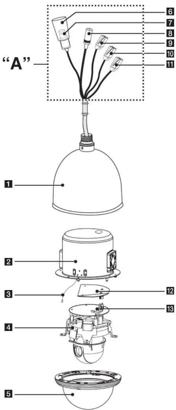
Identification of Camera
text_image
"A" 1 2 3 4 5 6 7 8 9 10 11 12 131 Dome camera body
2 Camera mounting bracket
3 Fall Prevention Wire
Be sure to hook the fall prevention wire into a bracket.
Caution:
When you fix the dome cover to the dome camera body, you must insert the wire in the dome camera body. If not, the wire may obstruct the camera's moving.
4 Mechanics assembly
5 Dome cover assembly
6 BNC connector cover cap
7 Video output cable with BNC connector Connects with the video connector of the monitor.
8 Power cable (AC 24V)
9 Data Communication Port (RJ45) - RS-485 and Alarm Input
10 Data Communication Port (RJ45) - RS-485 and Alarm Input
11 Data Communication Port (RJ45) - Alarm Output
12 IF board
13 Main control board
“A” Do not expose the power and data cable to moisture, this may cause leakage into the housing and damage the camera. If you must, please make sure that the connections are sealed tightly.
Installation
Precautions
The following steps of installation and connection work should be done by qualified service personnel or system installers and should conform to all local codes.
Before you install and connect the camera, check and prepare the required peripheral devices and cables.
Before you connect the camera, turn off all devices to be connected, such as this camera and DVR.
Note:
Do not touch the dome cover's window.
Camera Installation Location
Discuss the installation location for the camera with your retailer, and select a place that is strong enough for the installation.
• Install the camera on a ceiling (concrete, etc.) at a location that is sufficiently strong to support it.
• Install the camera body on the foundation section of the building or sections having sufficient bearing strength.
Never install or use the camera in the following locations
- Do not install it in areas exposed to direct sunlight or rain.
- Do not install the camera near the air outlet of an air conditioner.
- Near a swimming pool or other areas where chemicals are used.
- Food preparation areas and other locations where there are large amounts of steam vapor and oil, in flammable atmospheres, other special environments.
- Areas where radiation, X-rays, strong electric waves, or magnetism is generated.
- At sea, in coastal areas, or in areas where corrosive gas is being generated.
- Areas outside of the allowable ambient operating temperature range.
About Static Electricity Removal
Before installing the camera, touch a metal case or other metallic parts with your hand to remove static electricity from your body.
Do not install in areas subjected to high amounts of humidity or dust.
Doing so may cause internal components to damage more easily or malfunction.
Do not wire cables near power lines.
Tightening the Screws
Screws should be tightened sufficiently in accordance with the materials and structure of the installation location. After tightening the screws, visually inspect them to make sure there is no unevenness and that each screw is tight.
Removing the Protection Tape
Before using the camera, remove the protection tape.
Caution: Remove the protection tape carefully.
- Loosen the screws using the wrench and remove the dome cover as shown below.
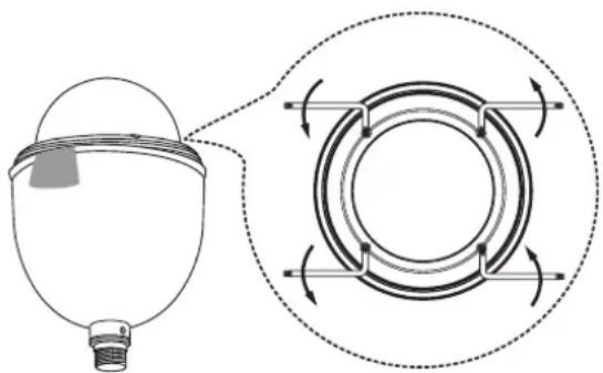
natural_image
Diagram of a medical device with a circular component and directional arrows indicating rotation or flow (no text or symbols)- Remove the protection tape and attach the dome cover.
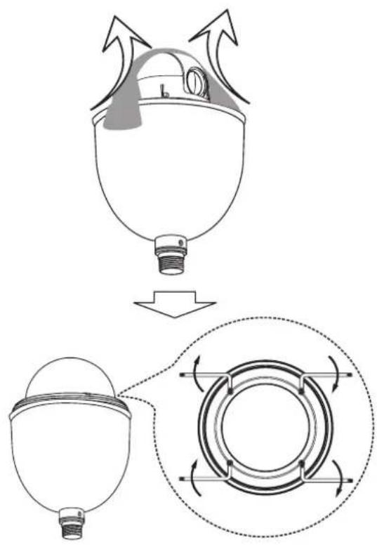
natural_image
Diagram of a mechanical component with arrows indicating motion, showing a top-down view and internal rotation (no text or symbols)Mounting the Camera
The figures show an example of the camera mounted on a wall with a locally procured bracket.
Note:
The camera have not been evaluated for wall or ceiling mounting.
Pendant mount (Optional)
Install pipe and camera as shown below.

text_image
"A"Wall mount (Optional)
Install the camera in the following order.
-
Drill holes on the wall where you want to install the pipe.
-
Install the pipe and camera as shown below.

text_image
"A"How to install
“A” Pipe threads should be clean and rust free. Use a sealer (such as Teflon™ tape and silicone sealer) on the threads.
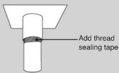
text_image
Add thread sealing tapeNote:
The pipes and brackets for mounting are not supplied.
Reference: Specifications of LG Standard pipe.
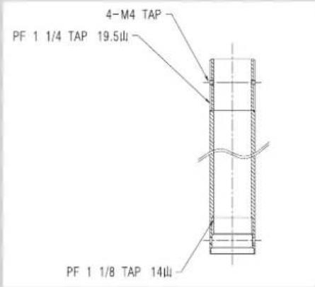
text_image
4-M4 TAP PF 1 1/4 TAP 19.5山 PF 1 1/8 TAP 14山Dipswitch Setting
The camera has one 8 bit switches that determine the protocol and baud rate of the data communication. Settings are loaded when the camera boots up. Be sure to turn the camera off, change the dipswitch settings, then power back up to load the changes.
- Turn off the camera.
- Remove the dome cover from the housing.
- Set the dipswitches inside the housing as per the table below.
- Power up the camera to load the changes.

text_image
SW2 on main board ON 12345678 ON OFF| Switch position (5-8) Protocol | |
 (OFF OFF OFF OFF) (OFF OFF OFF OFF) | LG Multix |
 (ON OFF OFF OFF) (ON OFF OFF OFF) | Reserved 1 |
 (OFF ON OFF OFF) (OFF ON OFF OFF) | Pelco D |
 (ON ON OFF OFF) (ON ON OFF OFF) | Pelco P |
Note:
If you are not using the controller with LG Multix protocol, there may be some limitation of function control.
| Switch position (1-4) BAUD RATE | |
| (OFF OFF OFF OFF) | 9,600 BPS |
| (ON OFF OFF OFF) | 1,200 BPS |
| (OFF ON OFF OFF) | 2,400 BPS |
| (ON ON OFF OFF) | 4,800 BPS |
| (OFF OFF ON OFF) | 19,200 BPS |
| (ON OFF ON OFF) | 38,400 BPS |
| (OFF ON ON OFF) | 57,600 BPS |
| (ON ON ON OFF) | 115,200 BPS |
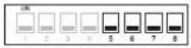
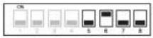
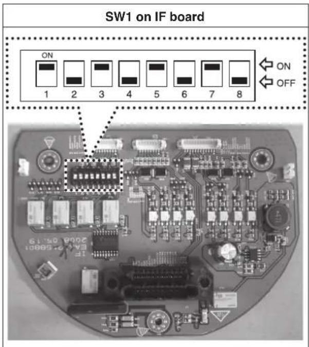
Alarm Output Mode Setting
You can set the Alarm Output to the normal open or normal close mode.
text_image
SW1 on IF board ON 1 2 3 4 5 6 7 8 ON OFF 2008-05-19 3A:2.68001| Alarm Output Number | Switch Number (Position) | Function Effect |
| 1 | 1 (ON), 2 (OFF) | Normal Open mode |
| 1 (OFF), 2 (ON) | Normal Close mode | |
| 2 | 3 (ON), 4 (OFF) | Normal Open mode |
| 3 (OFF), 4 (ON) | Normal Close mode | |
| 3 | 5 (ON), 6 (OFF) | Normal Open mode |
| 5 (OFF), 6 (ON) | Normal Close mode | |
| 4 | 7 (ON), 8 (OFF) | Normal Open mode |
| 7 (OFF), 8 (ON) | Normal Close mode |
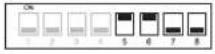
Camera ID Setting
If you want to use multiple cameras, you should set camera IDs differently by using the 8-bit Dip switch for each camera.
Set the camera ID setting referring to the pictures and the table on the below.
• The default setting of the camera ID is 0.

text_image
SW1 on main board ON 12345678 ON OFFThe table for the camera ID setting
- The connections should be made by qualified service personnel or system installers in accordance with all local codes.
• AC 24V can be used.
Note:
When powered up, the unit performs a self-check (including one panning, tilting, zooming and focusing operation).
Connection preview
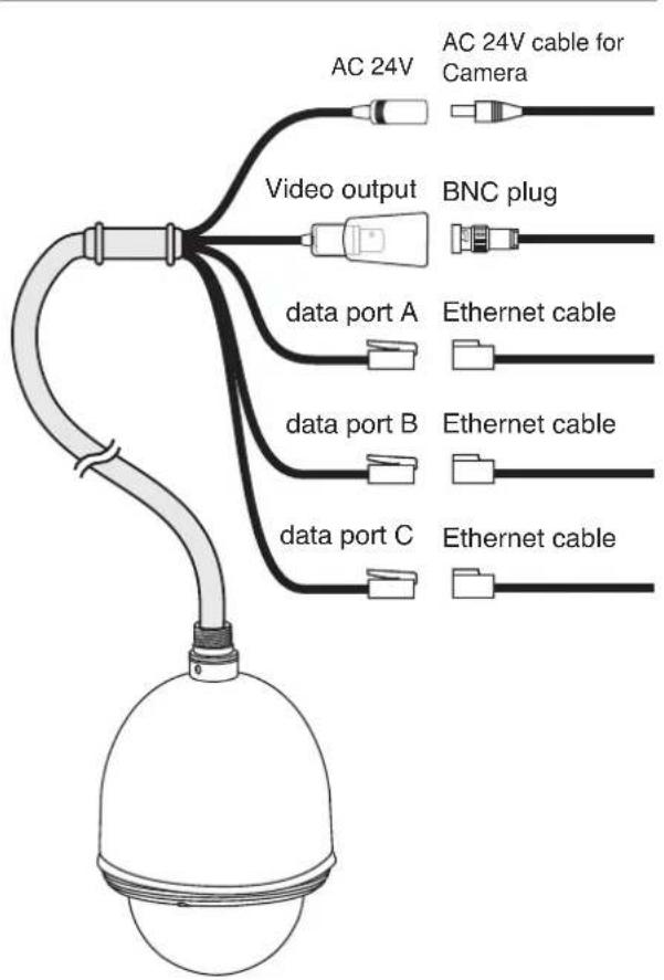
flowchart
graph TD
    A["AC 24V"] --> B["Video output"]
    B --> C["BNC plug"]
    C --> D["data port A"]
    C --> E["Ethernet cable"]
    D --> F["data port B"]
    F --> G["Ethernet cable"]
    G --> H["data port C"]
    H --> I["Ethernet cable"]
    style A fill:#f9f,stroke:#333
    style B fill:#ccf,stroke:#333
    style C fill:#cfc,stroke:#333
    style D fill:#fcc,stroke:#333
    style E fill:#cff,stroke:#333
    style F fill:#ffc,stroke:#333
    style G fill:#cfc,stroke:#333
    style H fill:#fcc,stroke:#333
RS-485 connection
Use the cable that is described below for RS-485 site communication.
• Shielded, twisted pair cable
- Low impedance
- Wire gauge size is thicker than AWG #22 (0.33 mm ^2 ).
Connecting monitor
The video signal connection between the camera and the monitor.
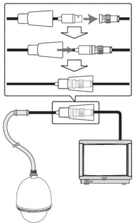
flowchart
graph TD
    A["Wireless Cable"] --> B["Switch"]
    B --> C["Connector"]
    C --> D["Switch"]
    D --> E["Connector"]
    E --> F["Switch"]
    F --> G["Monitor"]
Connecting power source
Connect a AC 24 V power source to the power input terminal.
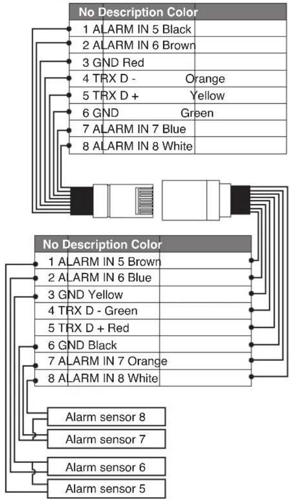
ALARM IN connections
Connect external sensors to the 8-pin hanes connector. Each alarm sensor should be connected with G (GND). Input specifications are low-active, non-voltage contact (ON when active) or open collector (Low when active).
Cautions
- Alarm input connection must be connected to only one port of two communication ports.
- Do not connect one alarm sensor to the several camera's alarm input connector.

flowchart
graph TD
    A["Data Port A Adapter"] --> B["Alarm sensors (1-4)"]
    A --> C["Data Port B Adapter"]
    C --> D["Alarm sensors (5-8)"]
Connection of the data port and adapter for alarm input
- Data Port A
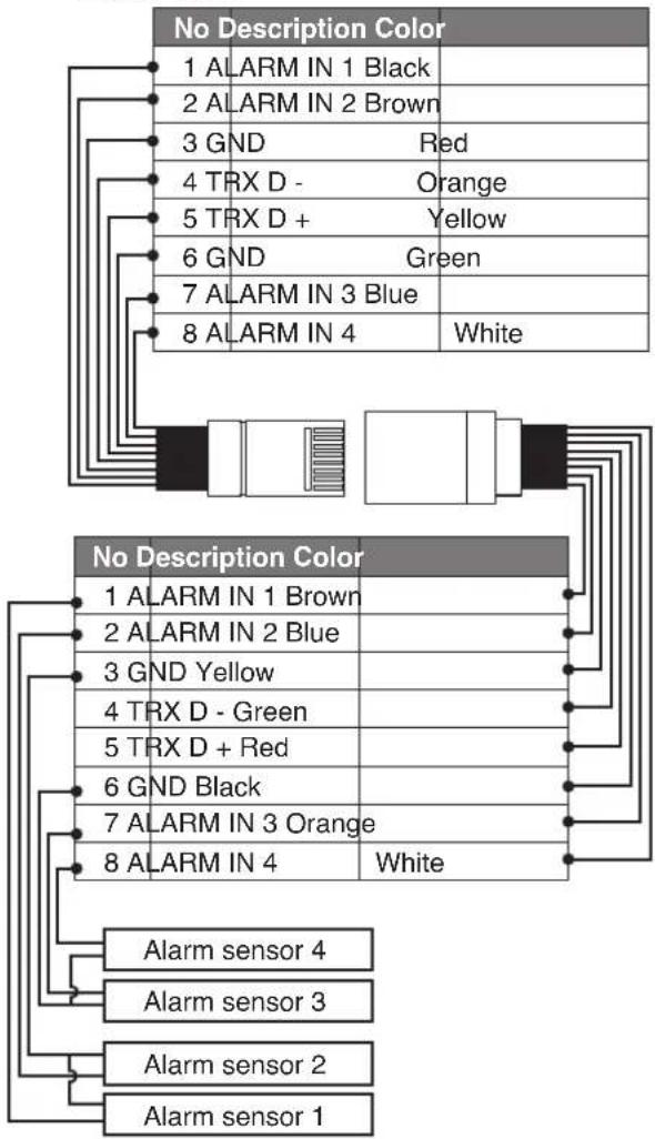
flowchart
graph TD
    A["No Description Color"] --> B["1 ALARM IN 1 Black"]
    A --> C["2 ALARM IN 2 Brown"]
    A --> D["3 GND Red"]
    A --> E["4 TRX D - Orange"]
    A --> F["5 TRX D + Yellow"]
    A --> G["6 GND Green"]
    A --> H["7 ALARM IN 3 Blue"]
    A --> I["8 ALARM IN 4 White"]

    J["No Description Color"] --> K["1 ALARM IN 1 Brown"]
    J --> L["2 ALARM IN 2 Blue"]
    J --> M["3 GND Yellow"]
    J --> N["4 TRX D - Green"]
    J --> O["5 TRX D + Red"]
    J --> P["6 GND Black"]
    J --> Q["7 ALARM IN 3 Orange"]
    J --> R["8 ALARM IN 4 White"]

    S["Alarm sensor 4"] --> T["Alarm sensor 3"]
    S --> U["Alarm sensor 2"]
    S --> V["Alarm sensor 1"]
Data Port B
flowchart
graph TD
    A["No Description Color"] --> B["1 ALARM IN 5 Black"]
    A --> C["2 ALARM IN 6 Brown"]
    A --> D["3 GND Red"]
    A --> E["4 TRX D - Orange"]
    A --> F["5 TRX D + Yellow"]
    A --> G["6 GND Green"]
    A --> H["7 ALARM IN 7 Blue"]
    A --> I["8 ALARM IN 8 White"]
    J["No Description Color"] --> K["1 ALARM IN 5 Brown"]
    J --> L["2 ALARM IN 6 Blue"]
    J --> M["3 GND Yellow"]
    J --> N["4 TRX D - Green"]
    J --> O["5 TRX D + Red"]
    J --> P["6 GND Black"]
    J --> Q["7 ALARM IN 7 Orange"]
    J --> R["8 ALARM IN 8 White"]
    S["Alarm sensor 8"] --> T["Alarm sensor 7"]
    U["Alarm sensor 6"] --> V["Alarm sensor 5"]
Alarm Input function
This speed dome camera has a terminal that can sense the alarm signals.
If the alarm sensor that has installed in a door, window, safe etc. sense a touch or shock, the alarm sensor send the alarm signal to the camera and the camera will observe the sensed position.
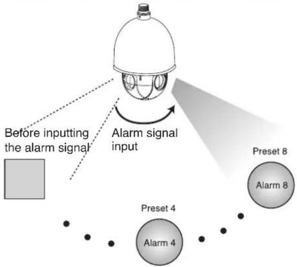
There are "Manual mode" and "Auto mode" for the Alarm Input function.
- Manual mode: Change the observe position to a sensor that senses a touch or shock then keep observe the sensed position. (Set the Duration Time of Alarm Input function to "0" using the LKD1000 controller.)
flowchart
graph TD
    A["Before inputting the alarm signal"] --> B["Alarm signal input"]
    B --> C["Preset 4"]
    B --> D["Alarm 4"]
    B --> E["Preset 8"]
    E --> F["Output"]
| Function status | Manual mode |
| While observe a specific position. | Change the observe position to the alarmed position then keep observe the alarmed position and you cannot control the camera. If you want to control the camera, you should set the Duration Time of Alarm Input function to "1 to 255" using the LKD1000 controller. |
| While operating Preset Tour function. | Stop preset touring and change the observe position to the alarmed position then keep observe the alarmed position. |
| While operating Auto Pan function. | Stop auto panning and change the observe position to the alarmed position then keep observe the alarmed position. |
| While operating Pattern function. | Stop operating pattern function and change the observe position to the alarmed position then keep observe the alarmed position. |
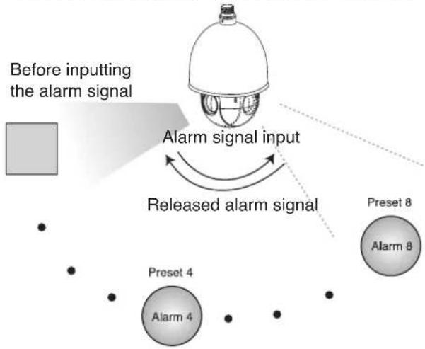
- Auto mode: Change the observe position to a sensor that senses a touch or shock then return to the position that previously observed. (Set the Duration Time of Alarm Input function to "1 to 255".)
flowchart
graph TD
    A["Before inputting the alarm signal"] --> B["Alarm signal input"]
    B --> C["Released alarm signal"]
    C --> D["Preset 4"]
    C --> E["Preset 8"]
    D --> F["Alarm 4"]
    E --> G["Alarm 8"]
| Function status | Auto mode |
| While observe a specific position. | Change the observe position to the alarmed position then return to the position that previously observed. |
| While operating Preset Tour function. | Stop preset touring and change the observe position to the alarmed position then restart the preset touring again. |
| While operating Auto Pan function. | Stop auto panning and change the observe position to the alarmed position then restart the auto panning again. |
| While operating Pattern function. | Stop operating pattern function and change the observe position to the alarmed position then restart the pattern function again. |
Note:
The Alarm In 1 is Preset 1, Alarm In 2 is Preset 2, Alarm In 3 is Preset 3,...,Alarm In 7 is Preset 7 and Alarm In 8 is Preset 8.
ALARM OUT connections
Connect an external device, for example, a buzzer or lamp, to this connector. Output specifications are low-active, open-collector and a drive capacity of 30V DC 0.5A maximum.
Alarm output numbers 1 to 4 are linked to alarm inputs 1 to 4 respectively. If alarm input 1 comes in, the camera sends output signals via the alarm output 1 connector on the camera.
Note:
Use a relay if the voltage or current of the connected device exceeds the ratings.

text_image
Data Port C Adapter Alarm devices (1-4)Connection of the data port and adapter for alarm output
- Data Port C

flowchart
graph TD
    A["No Description Color"] --> B["1 ALARM OUT 1 Black"]
    A --> C["2 COM 1 Brown"]
    A --> D["3 ALARM OUT 2 Red"]
    A --> E["4 COM 2 Orange"]
    A --> F["5 ALARM OUT 3 Yellow"]
    A --> G["6 COM 3 Green"]
    A --> H["7 ALARM OUT 4 Blue"]
    A --> I["8 COM 4 White"]
    J["No Description Color"] --> K["1 ALARM OUT 1 Brown"]
    J --> L["2 COM 1 Blue"]
    J --> M["3 ALARM OUT 2 Yellow"]
    J --> N["4 COM 2 Green"]
    J --> O["5 ALARM OUT 3 Red"]
    J --> P["6 COM 3 Black"]
    J --> Q["7 ALARM OUT 4 Orange"]
    J --> R["8 COM 4 White"]
    S["Alarm device 4"] --> T["Alarm device 3"]
    U["Alarm device 2"] --> V["Alarm device 1"]
Connecting LKD1000 controller
Connecting the LKD1000 controller to control the camera. (Refer to the manuals of the LKD1000 controller for more details.).

text_image
Data Port A or B Adapter LKD1000 controllerConnection of the data port and adapter with LKD1000 controller
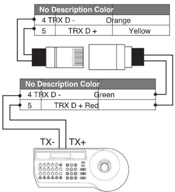
flowchart
graph TD
    A["No Description Color"] --> B["4 TRX D - Orange"]
    A --> C["5 TRX D + Yellow"]
    D["No Description Color"] --> E["4 TRX D - Green"]
    D --> F["5 TRX D + Red"]
    G["TX- TX+"] --> H["Display"]
System Connection
Note:
When any peripheral is turned off and turned on again, the camera is also turned off and turned back on.
Caution:
Do not connect the alarm connectors to the another camera's alarm connectors.

flowchart
graph TD
    A["Controller"] --> B["A"]
    C["DVR"] --> D["A"]
    D --> E["or"]
    E --> F["To Alarm devices"]
    G["Alarm In #1"] --> H["A"]
    I["Alarm In #2"] --> J["A"]
    K["Alarm In #3"] --> L["A"]
    M["Alarm In #4"] --> N["A"]
    O["Caution: Connect the supplied termination adapter to the final camera's data port (B) to prevent the RS-485 communication error."] --> P["B"]
    Q["To Alarm devices"] --> R["C"]
Operation
Setup Menu Overview
The following table shows the list of menu items and options. You can adapt the camera to your requirements by setting up the respective items in these menus.
| Main Menu Sub Menu Contents | |||
| FOCUS | FOCUS MODE | AUTO/ ONE PUSH/ ZOOM TRIG/ MANUAL | |
| FOCUS DIST 5 | 0CM, 1.8M, 3M, 6M | ||
| ZOOM START x1~x36 | |||
| ZOOM END x2~x444 | |||
| ZOOM SPEED $ | LOW/ MIDDLE/ QUICK | ||
| ZTRK MODE | AUTO/ MANUAL/ AUTO ONLY | ||
| INITIAL SET | |||
| EXIT RET/TOP/END | |||
| EXPOSURE | IRIS AUTO/MANUAL | ||
| AGC OFF/LOW/MIDDLE/HIGH | |||
| WDR/BLC OFF/WDR/BLC/HSBLC | |||
| BRIGHTNESS 0~100 | |||
| SHUTTER | X512, ~, x2, AUTO, OFF, A.FLK, 1/160, ~, 1/90000 | ||
| SENS-UP | OFF, AUTO x2 ~ AUTO x128 | ||
| INITIAL SET | |||
| EXIT RET/TOP/END | |||
| WHITE BALANCE | ATW | ||
| AUTO | |||
| ONE PUSH | |||
| MANUAL | COLOR TEMP | INDOOR, OUTDOOR | |
| RED -100 | ~ 100 | ||
| BLUE -100 | ~ 100 | ||
| INITIAL SET | |||
| EXIT | RET/TOP/ END | ||
| Main Menu Sub Menu Contents | |||
| DAY/NIGHT | AUTO | D/N LEVEL | LOW/MIDDLE/HIGH |
| DWELL TIME | 5, 10, 15,30, 60 sec | ||
| INITIAL SET | |||
| EXIT | RET/TOP/END | ||
| DAY | |||
| NIGHT | |||
| MOTION DET | OFF | ||
| ON | ZONE NUMBER | ZONE1 ~ZONE4 | |
| ZONE STATE | OFF, ON | ||
| WIDTH | |||
| HEIGHT | |||
| MOVE X | |||
| MOVE Y | |||
| SENSITIVITY | |||
| INITIAL SET | |||
| EXIT | RET/TOP/END | ||
| PRIVACY MASK | OFF | ||
| ON | MASK NUMBER | MASK1 ~MASK8 | |
| MASK STATE | OFF, ON | ||
| MASK COLOR | BLACK,GRAY,WHITE | ||
| WIDTH | |||
| HEIGHT | |||
| MOVE X | |||
| MOVE Y | |||
| RESET MASK | |||
| INITIAL SET | |||
| EXIT | RET/TOP/END | ||
| 3D-DNR | OFF | ||
| LOW | |||
| MIDDLE | |||
| HIGH | |||
| Main Menu Sub Menu Contents | |||
| SPECIAL | CAMERA ID 0~255 | ||
| D-EFFECT Not supported. | |||
| COLOR | OFF | ||
| ON COLOR LEVEL | |||
| FREEZE OFF/ ON | |||
| SHARPNESS 0~68 | |||
| STABILIZER OFF/ ON | |||
| OSD | OFF | ||
| ON | USER TITLE | ||
| ZOOM MAG | |||
| FUNCTION | |||
| CAMERA ID | |||
| LANGUAGE | ENG (The supported language can be different depending on the model.) | ||
| INITIAL SET | |||
| EXIT RET/TOP/END | |||
| RESET | FACTORY RESET | ||
| S/W VERSION | |||
| REBOOT | |||
| EXIT RET/TOP/END | |||
| EXIT | |||
Note:
The Preset, Auto Pan, Pattern, Alarm functions could not be set on the OSD menu. To set these functions, use LKD1000 controller.
Menu navigation
We use the LKD1000 controller in this manual to explain the features of the LG Dome camera because of the LKD1000's ability to control all of the LG Dome camera's advanced features. (For detailed controller instructions, refer to the LKD1000 Controller Manual.)
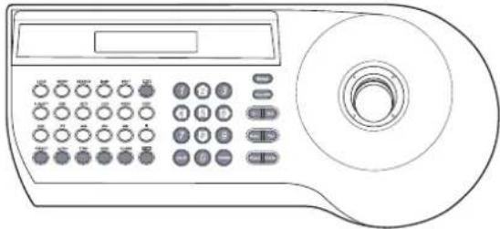
natural_image
Line drawing of a handheld electronic device with control panel and CD (no text or symbols)| Buttons Function | ||
 | Cam OSD button | Displays the setup menu or cancels operation of the setup menu. |
 | ZOOM IN button | Use to move upper direction on the menu screen. |
| ZOOM OUT button | Use to move lower direc-tion on the menu screen. | |
 | FOCUS NEAR but-ton | Use for increase the value of the option. |
| FOCUS FAR button | Use for decrease the value of the option. | |
 | Open/Close(Enter) buttons | Executes selections and displays a submenu for an item with the mark. |
Accessing setup menus
To access the setup menus using the keys on a LKD1000 controller, do the following:
- Select CAM (Camera) icon in the main menu and then press ENTER. The camera ID input menu will be displayed.
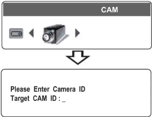
flowchart
graph TD
    A["CAM"] --> B["Camera Icon"]
    B --> C["Down Arrow"]
    C --> D["Please Enter Camera ID\nTarget CAM ID: _"]
- Enter the connected camera ID to control the camera connected to the LKD1000 controller directly and then press ENTER. The camera control menu will be displayed.

text_image
PRESET /CAM1- Press [Cam OSD] button to display the camera setup menu.
text_image
At this point, you have access to the camera setup menu.
General Operation
- Use [In] or [Out] button to select an option then press [Open] or [Close] button. Submenu appears on the monitor.
- Use [In] or [Out] button to select a submenu option.
- Use [Near] or [Far] button to select a value.
- Select [EXIT] option then press [Open] or [Close] to exit the setup menu. In the submenu, use [In] or [Out] button to select the [EXIT] then use [Near] or [Far] button to select a mode and press [Open] or [Close] to exit the setup menu.
• RET: Return to the previous.
- TOP: Return to the CAMERA SETTING menu screen.
• END: Exit the setup menu.
Focus setting
Focus Mode setting

text_image
The camera adjusts the focus automatically by sensing the center of the picture.
Select [FOCUS MODE] option on the [FOCUS] menu, then select the following mode.
• AUTO: Auto-focus is activated automatically.
- ONE PUSH: The focus is activated manually. If the camera is received auto-focus command, the camera is activated Auto-focus mode and the focus is set automatically and then the focus mode is automatically changed to manual mode.
- ZOOM TRIG: The focus is activated manually. If you change the zoom, the focus is activated Automatically and then the focus mode is automatically changed to manual mode.
- MANUAL: Focus is activated only when the FOCUS (NEAR or FAR) keys on the controller is pressed.
Focus Distance setting
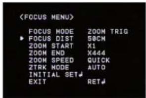
text_image
Selects the minimum shooting distance for the focus. Select [FOCUS DIST] option on the [FOCUS] menu, then select a focus distance value (50CM, 1.8M, 3M, 6M).
Zoom Start setting
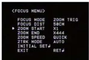
text_image
You can set the zoom start position of the camera. When the zoom function is operated, the zoom always will start at the selected zoom start position.
Select [ZOOM START] option on the [FOCUS] menu, then set a zoom start position (x1 - x36).
Zoom End setting
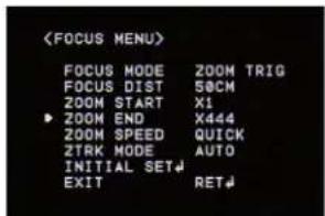
text_image
You can set the zoom end position of the camera. If you set the zoom end position, the zoom is operated up to the selected zoom end position.
Select [ZOOM END] option on the [FOCUS] menu, then set the zoom end position ("Zoom Start position+1" \~ x444).
Zoom Speed setting
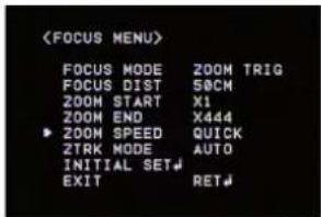
text_image
Selects a zoom speed. Select [ZOOM SPEED] option on the [FOCUS] menu, then select a zoom speed (SLOW, MIDDLE or QUICK).
Zoom Tracking Mode setting
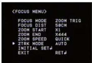
text_image
Selects a zoom tracking mode. Zoom tracking means focused zooming state.
Select [ZTRK MODE] option on the [FOCUS] menu, then select a zoom tracking mode (AUTO or MANUAL).
If the FOCUS MODE is set to [AUTO], the ZTRK MODE is set to [AUTO] and you can not change the ZTRK MODE.
Exposure settings
Iris setting

text_image
Select the desired lens iris value for camera exposure. Select [IRIS] option on the [EXPOSURE] menu, then select a value. (AUTO or MANUAL).
• AUTO: The lens iris is set automatically.
- MANUAL: Use [Near] or [Far] button to select the DC Iris level.
AGC (Automatic Gain Control) setting
If the images are too dark, change the maximum [AGC] value to make the images lighter.
- Select [AGC] option on the [EXPOSURE] menu.

text_image
- Use [Near] or [Far] button to select a mode. (OFF←→ LOW←→MIDDLE←→HIGH)
WDR/BLC setting
Use WDR/BLC option to set the options for BLC or WDR camera.
- Select [WDR/BLC] option on the [EXPOSURE] menu.

text_image
- Use [Near] or [Far] button to select a mode then press [Open] or [Close].
• WDR: Set the WDR limit.
- WDR LEVEL: LOW ↔ MIDDLE ↔ HIGH
• BLC: Set the BLC limit.
- BLC LEVEL: LOW ↔ MIDDLE ↔ HIGH
- HSBLC: Use for adjusting brightness the specific area of picture. The HSBLC mode is automatically activated only in low illuminance scene.
- AREA SETTING: Use [Near] or [Far] button to select a area then use [In] or [Out] button to select a ON or OFF. Press [Open] or [Close] to exit the area setting menu.
- GRAY SCALE: Use [Near] or [Far] button to select a gray scale. (GRAY↔D.GRAY↔BLACK).
- HS LEVEL: Use [Near] or [Far] button to select a bright level. (5 level)
- MASK STATE: Use [Near] or [Far] button to select [ON] or [OFF]. If you set the MASK STATE to ON, the mask function is activate only when the HSBLC is activated by auto mode.
• OFF: Not used.
BRIGHTNESS setting
You can increase the brightness of the darkened video. If you set the brightness to lower value, the image is darkened. If you set the brightness to higher value, the image gets bright.
- Select [BRIGHTNESS] option on the [EXPOSURE] menu.
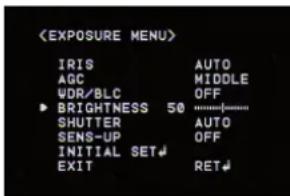
text_image
- Use [Near] or [Far] button to set the bright level.
SHUTTER (Shutter Speed) setting
Select the desired shutter speed for camera exposure. You can change the shutter speed to higher speed to capture fast-moving subjects, though the image becomes darker.
- Select [SHUTTER] option on the [EXPOSURE] menu.
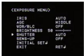
text_image
- Use [Near] or [Far] button to set shutter speed. (x512\~x2 ↔ AUTO↔ OFF ↔ A.FLK ↔ 1/160 \~ 1/90000)
SENS-UP setting
If pictures are not clear due to darkness, use for increase the sensitivity of picture.
- Select [SENS-UP] option on the [EXPOSURE] menu.
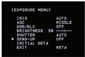
text_image
- Use [Near] or [Far] button to set the SENS-UP limit (OFF, AUTO x2 \~ AUTO x128). To setting the SENS-UP function, select the [AUTO] on the [SHUTTER].
Note:
If you set to one of the SHUTTER options except AUTO on the [SHUTTER] menu, the [SENS-UP] setting is not available and [---] mark is displayed.
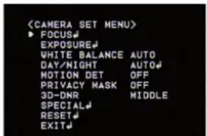
White Balance setting
Select the method by which the camera shifts its output colors to compensate for the color of a light source.
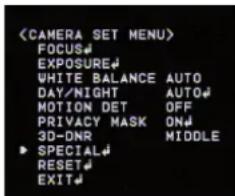
- Select [WHITE BALANCE] option on the [CAMERA SET] menu.

text_image
-
Use [Near] or [Far] button to select a mode then press [Open] or [Close].
-
ATW (Auto-Tracing White Balance): In this mode, the color temperature range for the proper white balance is approximately 1,800 - 10,500°K. Proper white balance may not be obtained under the following conditions:
- When the color temperature is out of the 1,800 - 10,500°K range.
- When the scene contains mostly high color temperature objects, such as a blue sky or sunset.
- When the scene is dim.
- AUTO: In this mode, the color temperature range for the proper white balance is approximately 2,700 - 5,400°K. Proper white balance may not be obtained under the following conditions:
- When the color temperature is out of the 2,700 - 5,400°K range.
- When the scene contains mostly high color temperature objects, such as a blue sky or sunset.
- When the scene is dim.
- ONE PUSH: If you select the ONE PUSH mode, you will be able to set up the White Balance automatically using [Open] or [Close] button.
- MANUAL: You can set the white balance options manually.
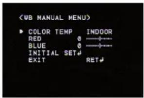
text_image
- COLOR TEMP: Use [Near] or [Far] button to select a function.
INDOOR: The color temperature range for the proper white balance is approximately 3,200^ >OUTDOOR: The color temperature range for the proper white balance is approximately 5,100^
- RED: Set the desired red value. (-100\~100)
- BLUE: Set the desired blue value. (-100\~100)
Day/Night setting
- Select [DAY/NIGHT] option on the [CAMERA SET] menu.

text_image
- Use [Near] or [Far] button to select mode for day/night function.
- AUTO: You will be able to change the Day/Night mode automatically.

text_image
- D/N LEVEL: Use [Near] or [Far] button to select a level. (LOW←→MIDDLE←→HIGH)
- DWELL TIME: Use [Near] or [Far] button to select a dwell time. (5, 10, 15, 30 or 60 sec.)
Note:
If you set the AGC to [OFF] or the SHUTTER
is set to one of the SHUTTER options except AUTO on the [EXPOSURE] menu, the AUTO mode of the DAY/NIGHT function is not available and [---] mark is displayed.
• DAY: Color mode enabled.
• NIGHT: Black-and-white mode enabled.
Motion Detection setting
The motion detection detects the moving objects in the scene by monitoring changes in brightness level. You can select the level of sensitivity for motion detection to 4 zone.
- Select [MOTION DET] option on the [CAMERA SET] menu.
- Use [Near] or [Far] button to select a [ON] and press [Open] or [Close]. The MOTION DETECTION menu appears.
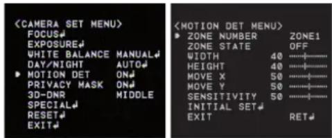
text_image
- Use [Near] or [Far] button to select a zone number (ZONE1 \~ ZONE4) on the [ZONE NUMBER] option.
- Use [Near] or [Far] button to set up the ON or OFF on the [ZONE STATE] option. If you set to ON, the zone frame appears on the center of the monitor.
-
Use [In] or [Out] to select an option then use [Near] or [Far] button to adjust the option
-
WIDTH: Enlarge or decrease the horizontal size of the zone frame.
-
HEIGHT: Enlarge or decrease the vertical size of the zone frame.
• MOVE X: Moves horizontal position of the zone frame.
• MOVE Y: Moves vertical position of the zone frame. -
Use [SENSITIVITY] option to obtain the optimum detection level.
Privacy Mask setting
This function is aiming at the protection of personal privacy, selecting a screen part black not to be displayed in the screen. Up to 8 zones can be registered.
- Select [PRIVACY MASK] option on the [CAMERA SET] menu.
- Use [Near] or [Far] button to select a [ON] and press [Open] or [Close]. The PRIVACY MASK menu appears.
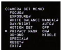
text_image
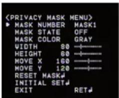
text_image
- Use [Near] or [Far] button to select a zone number (MASK1 \~ MASK8) on the [MASK NUMBER] option.
- Use [Near] or [Far] button to set up the ON or OFF on the [MASK STATE] option. If you already registered the mask zone and set to ON, the mask zone box appears on the monitor.
- Use [Near] or [Far] button to select the color of the mask zone box on the [MASK COLOR] option.
- Select [RESET MASK] and press [Open] or [Close]. If you register the mask zone for the first time, the mask zone box appears on the center of the monitor. If you already registered mask zone, it will be returned to its initial state and appear on the center of the monitor.
-
Use [In] or [Out] to select an option then use [Near] or [Far] button to adjust the option.
-
WIDTH: Enlarge or decrease the horizontal size of the mask zone box.
- HEIGHT: Enlarge or decrease the vertical size of the mask zone box.
• MOVE X: Moves horizontal position of the mask zone box. - MOVE Y: Moves vertical position of the mask zone box.
Notes:
- If you want to reset the mask zone position, select RESET MASK option and press [Open] or [Close] button.
- The parts with the registered mask numbers from MASK1 to MASK4 have the same color. (So do the parts with the numbers from MASK5 to MASK8). If you change the mask color, the reg-
istered mask color will be changed automatically with the same color for each of group (MASK1\~4, MASK5\~8).
3D-DNR setting
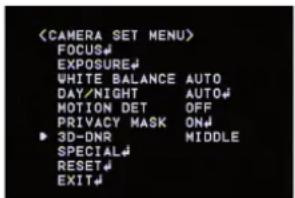
text_image
- Select [3D-DNR] option. If pictures are not clear due to brightness, use for reduce the noise of picture.
- Use [Near] or [Far] button to select a option. (OFF←LOW←MIDDLE←HIGH)
Notes:
• If you set the AGC to [OFF] on the [EXPOSURE] menu, the [3D-DNR] function is not available.
- When you use this function, the afterimage may occur.
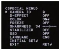
Special menu settings
Camera Identification setting
Only displays the camera's ID. Use the internal 8 bit-DIP switch if you want to set ID.
text_image
text_image
D-EFFECT (Digital effect) setting
This model does not support the D-EFFECT function.
Color setting
You can switch the displayed picture to grayscale or color.
- Select [COLOR] option on the [SPECIAL] menu.
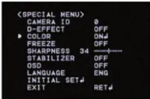
text_image
- Use [Near] or [Far] button to change a color effect.
- ON: To display the picture with color. Select ON and Press [Open] or [Close] to display the submenu. You can adjust the color level using the [Near] or [Far] button.
• OFF: To display the picture with grayscale.
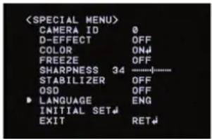
Freeze setting
- Select [FREEZE] option on the [SPECIAL] menu.
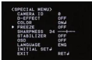
text_image
(SPECIAL MENU) CAMERA ID 0 D-EFFECT OFF COLOR ON FREEZE OFF SHARPNESS 34 ------------------ STABILIZER OFF OSD OFF LANGUAGE ENG INITIAL SET EXIT RET- Use [Near] or [Far] button to set up the ON or OFF.
Sharpness setting
Sharpens the image outline.
- Select [SHARPNESS] option on the [SPECIAL] menu.
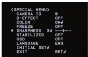
text_image
- Use [Near] or [Far] button to change a adjust the option. If you set the sharpness value to higher, the image outline becomes sharp. If you set to lower value, the image outline becomes dim.
Stabilizer setting
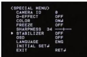
text_image
The image stabilizer function minimizes the appearance of shaky images caused by low-frequency vibration.
This function is useful for outdoor surveillance. Select [STABILIZER] option and set to ON or OFF.
Note:
If you set the [STABILIZER] to ON, the Digital zoom is set to [x1.1] automatically.
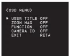
OSD setting
You can set the Function On-Screen Display options using the [OSD] menu.
The Function On-Screen Display of this camera can be turned on or off.
- Select [OSD] option on the [SPECIAL] menu.
- Use [Near] or [Far] button to select a [ON] and press [Open] or [Close]. The OSD menu appears.
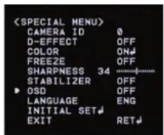
text_image

text_image
- Use [In] or [Out] to select an option then use [Near] or [Far] button to set the option.
• ON: Displays the Function OSD on the screen.
- OFF: The Function OSD does not appear on the screen.
User title setting
You can use the camera identification to assign a number and character to the camera (0 - 9, A-Z, a-z). The USER TITLE is displayed on the upper left of the screen.
To disappear the user title, select [OFF].
- Select [USER TITLE] option on the [SPECIAL] screen.
- Use [Near] or [Far] button to select a [ON] then press [Open] or [Close]. The USER TITLE menu appears.
text_image

text_image
-
Use [In], [Out], [Near] or [Far] button to select a character or number.
-
CLR: If you enter the wrong code, select CLR then press [Open] or [Close].
- POS: Use [Near] or [Far] button to move position of USER TITLE on the screen.
- END: Confirm your selection.
- 1(Blank): Insert a space at the cursor position.
- / Moves cursor to left or right.
Language setting
Select a language for setup menu and information display.
text_image
Reset settings
- Select [RESET] option.
- Press [Open] or [Close] button and the RESET menu appears.

text_image

text_image
-
Use [In] or [Out] to select option.
-
FACTORY RESET: Clear certain settings and information and return to factory default settings.
- S/W VERSION: Displays the software version on the monitor.
-
REBOOT: Reboot the camera system.
-
Press [Open] or [Close] to confirm your selection.
Reference
Specifications
| Signal System NTSC (High Resolution) | PAL (High Resolution) | |
| Pick-Up Device 1/4" EX-view HAD CCD | ||
| Total Pixels No 410K 470K | ||
| Horizontal Resolution More Than 540 TV Lines | ||
| Lens x37 Zoom ( F1.5(Wide Angle), F4.1(Tele)), f = 3.5mm ~ 129mm | ||
| S/N Ratio More Than 50dB (AGC Off) | ||
| Day & Night Day / Night / Auto | ||
| Min. Illumination(Lux) Color: 0.003 (0.6, Sens-up Off), B/W: 0.0001 (0.1, Sene-up Off) | ||
| Digital Zoom X 12 | ||
| Sync System Internal | ||
| White Balance Auto / ATW/ ONE PUSH / Manual(1,800 °K ~ 10,500 °K) | ||
| Control method RS-485 Control | ||
| Alarm Input | 8 Channel | |
| Alarm Output | 4 Channel | |
| Video Output Composite Output | 1Vp-p (75Ω Terminated) | |
| Electronic Shutter | 1/60 - 1/90,000 Sec | 1/50 - 1/90,000 Sec |
| Iris Control | Auto / Manual | |
| Wide Dynamic Range | Dual Shutter Control (60dB) | |
| Panning Range (Speed) | 0°~360°, Max. 240°/Sec | |
| Tilting Range (Speed) | 0° ~ 180°, Max. 240°/Sec | |
| Privacy Zone 8 Area Active Programmable Zone | ||
| Preset/ID | 128 Position / 256 | |
| Auto Panning | 2 - 8 points | |
| Pattern | Max. 8 minutes | |
| Group Tour | Max. 9 Groups | |
| Operation Temperature | -10~50 °C (Humidity: 0%RH~80%RH) | |
| Safekeeping Temperature | -30~60 °C (Humidity: 0%RH~85%RH) | |
| Power Supply | AC 24V | |
| Power Consumption Max. 20W | ||
| Dimension(ø x H ) | ø 230mm x 332mm(H) | |
| Weight | Approx 3.3Kg | |

LG