NTV-KIT751 - Kit automobile NAV-TV - Free user manual and instructions
Find the device manual for free NTV-KIT751 NAV-TV in PDF.

User questions about NTV-KIT751 NAV-TV
0 question about this device. Answer the ones you know or ask your own.
Ask a new question about this device
Download the instructions for your Kit automobile in PDF format for free! Find your manual NTV-KIT751 - NAV-TV and take your electronic device back in hand. On this page are published all the documents necessary for the use of your device. NTV-KIT751 by NAV-TV.
USER MANUAL NTV-KIT751 NAV-TV
natural_image
Interior view of a Audi car dashboard and steering wheel (no visible text or symbols)Overview
The AUDI-DYN INT Kit interfaces a backup camera (with dynamic guidelines) and one additional video input (front cam, etc) to the factory media screen in select Audi vehicles with the Concert media system (MMi controls on vercal radio face, not console).
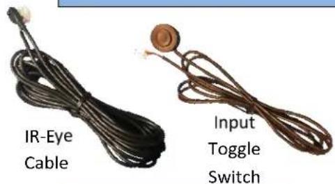
Kit Contents
text_image
IR-Eye Cable Input Toggle Switch
text_image
NORTY AUDI DYNAMIC INT. IOT NTV-KIT700
natural_image
Coiled black cable with yellow connectors, no visible text or symbolsVIDEO Input RCA

natural_image
Two brown cable connectors with gold contacts, labeled 'N Cable' below (no other text or symbols)AUDI-DYN INT Interface
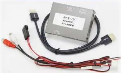
HD-LINK Oponal KIT800
natural_image
Exterior view of a gray industrial control unit with black and red cables, connectors, and a white label (no readable text on main subject)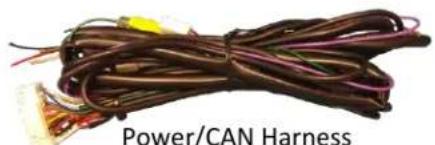
natural_image
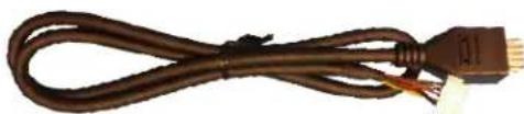
Coiled brown electrical wires with terminal connectors, labeled 'Power/CAN Harness' below (no other text or symbols visible)LVDS-IN Cable

OSD Menu
Remote
LVDS-OUT Cable
Agreement: End user agrees to use this product in compliance with all State and Federal laws. NAV-TV Corp. would not be held liable for misuse of its product. If you do not agree, please discontinue use immediately and return product to place of purchase. This product is intended for off-road use and passenger entertainment only.
BHM
11/21/17
NTV-DOC242
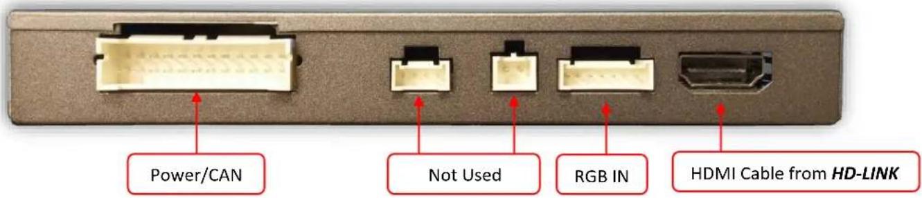
Interface Connectors
text_image
Power/CAN Not Used RGB IN HDMI Cable from HD-LINK
text_image
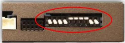
LVDS-IN LVDS-OUT Not Used Dip SwitchesDip Switch Sengs
| Dip SW: | 1 | 2 | 3 | 4 | 5 | 6 | 7 | 8 | 9 | 10 |
| UP | SkipsRGB | SkipsV1 | SkipsV2 | RVC OFF | N.C. | N.C. | N.C. | N.C. | HIGHRES | KeepDown |
| DOWN | EnablesRGB | EnablesV1 | EnablesV2 | RVC ON | N.C. | N.C. | N.C. | N.C. | LOWRES | KeepDown |
Upon buon presses
natural_image
Close-up of a black electronic component with a red oval highlight on its side (no visible text or symbols)Note: If the dip switches are not congured prior to installaon you must remove power to the unit prior to making adjustments to the dip switches.
Agreement: End user agrees to use this product in compliance with all State and Federal laws. NAV-TV Corp. would not be held liable for misuse of its product. If you do not agree, please discontinue use immediately and return product to place of purchase. This product is intended for off-road use and passenger entertainment only.
AUDI-DYN-INT Installaon
ATTENTION INSTALLER: All connecons (including CAN) must be made BEFORE connecng the power harness to this unit for proper startup operaon.
- Remove the factory screen. This requires removing the plasc screen bezel and then (4x) Torx T20 screws. Disconnect the 10-pin harness from the screen and set the screen aside.
-
Remove the factory radio (CD player). Disconnect all harnesses and set the radio aside.
-
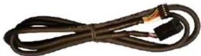
Connect the provided LVDS-OUT Cable to the OEM screen. This connector is keyed and will only t in one direcon. The other end of this cable connects to the interface at the port labeled 'LVDS OUT'.
natural_image
Coiled black cable with two connectors, no visible text or symbols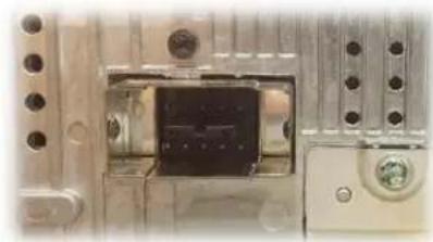
natural_image
Close-up of a mechanical or electronic component with no visible text or symbols- Connect the provided LVDS-IN Cable to OEM 10-pin square connector previously
connected to the screen (removed in step 1). The other end of this cable connects to the interface at the port labeled 'LVDS IN'.
natural_image
Coiled brown cable with connectors and a small connector at the end (no text or symbols visible)- Oponal: If adding an additional video input (front camera etc.), connect the provided Video Input RCA to the port on the AUDI interface labeled 'AV IN'. Connect the video signal to this RCA, be certain the video source is powered with an ACC source.

natural_image
Coiled black cable with yellow connectors, no visible text or symbols- Oponal: If this car is not equipped with OEM rear parking sensors, you may turn the visual overlay o in the OSD menu system (see page 5 for menu informaon).
Note: If adjusng any OSD menu sengs, temporarily connecng the provided AV toggle switch and IR-Eye is required. Both harness connectors are located among the main power harness (2-pin & 3-pin).

natural_image
Two types of cordages with black and brown wires, no text or symbols visibleAgreement: End user agrees to use this product in compliance with all State and Federal laws. NAV-TV Corp. would not be held liable for misuse of its product. If you do not agree, please discontinue use immediately and return product to place of purchase. This product is intended for off-road use and passenger entertainment only.
- Grab the provided Power/CAN Harness from the AUDI-DYN-INT kit. Use the chart below to locate and solder (splice, don't cut) the following wires to the car (you may have to extend a pair of CAN wires for some vehicles):
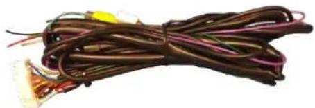
natural_image
Coiled brown electrical wires with various connectors (no visible text or symbols)| Vehicle | Interface wires | Connect to AUDI Wire: | Wire Locaon |
| ALL | GROUND (Black) | Brown (Ground -) | CAN Gateway |
| POWER (Red) | Black/White (ACC +) | CAN Gateway | |
| A4/A5/Q5 | CAN 1 HI (Blue) | CAN HI (Orange/Blue) | CAN Gateway (Right side of radio. Must remove glove box for access.) |
| CAN 1 LO (White) | CAN LO (Orange/Brown) | ||
| CAN 2 HI (Green) | CAN HI (Orange/Green) | CAN Gateway (Right side of radio. Must remove glove box for access.) | |
| CAN 2 LO (Pink) | CAN LO (Orange/Brown) |
AUDI A4, A5 CAN & Power Wires Locaon
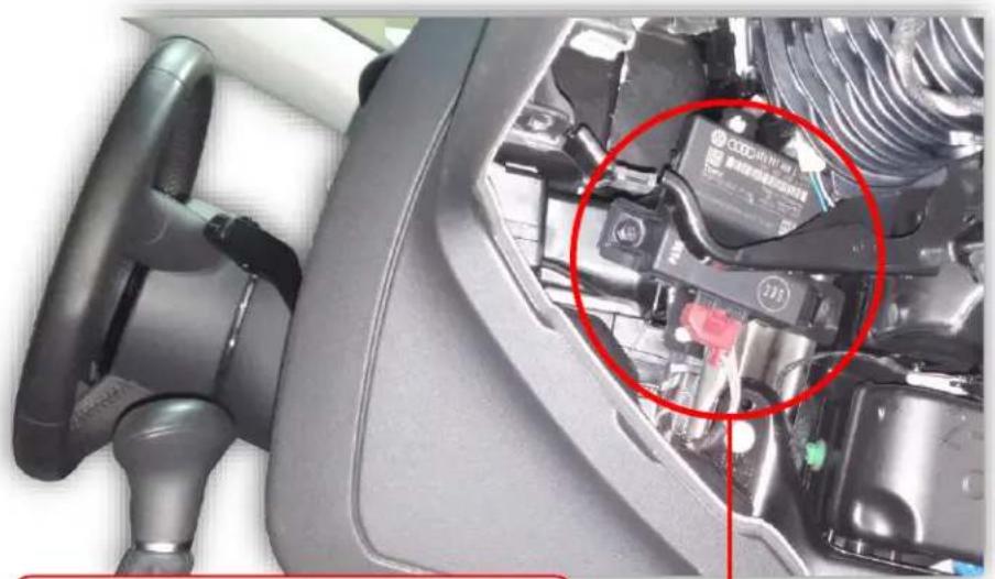
natural_image
Interior view of a car showing the engine compartment with a red circle highlighting a component (no visible text or symbols)CAN Gateway locaon ALL INT MMI: Right side of radio (drop glove box)
CAN Gateway
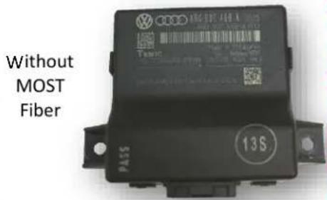
text_image
Without MOST Fiber PASS 13SAgreement: End user agrees to use this product in compliance with all State and Federal laws. NAV-TV Corp. would not be held liable for misuse of its product. If you do not agree, please discontinue use immediately and return product to place of purchase. This product is intended for off-road use and passenger entertainment only.
- Install your reverse camera and run signal, power and ground wires up front to the AUDI interface from step 7.
- Power your camera with an ACC source or the purple 12v reverse output wire (500 mA MAX). Find a solid ground (-) for the camera as well. NOTE: if using KIT381 (AUDI handle cam), cut o the connector and use black wire for ground and red for power.
- Connect the signal for your camera to the yellow RCA among the Power/CAN Harness labeled 'CAMERA'.
- Connect the 24-pin white plug from the Power/CAN Harness to the port on the AUDI-DYN INT interface labeled 'POWER/CAN'.
- Start the car and test for proper funconality before replacing dash pieces. If menu adjustments are needed (to remove sensor overlay, etc.), proceed to 'Menu Adjustments'
Note: All other included harnesses not menoned in this manual are not needed for most installaons. If you would like to know more about the full capability of this interface, contact NAV-TV tech support at 561-955-9770. Additional features not menoned in this manual are not supported by NAV-TV at this me.
Installaon Diagram
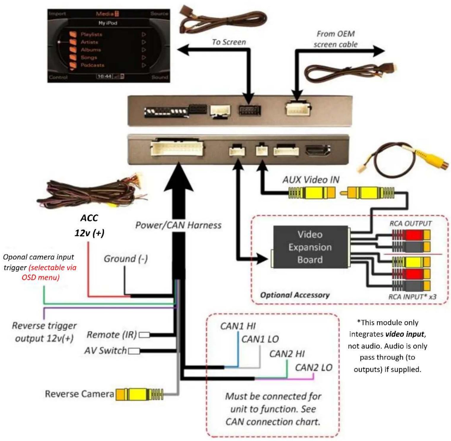
flowchart
graph TD
    A["Import Media Source"] -->|To Screen| B["Audio System"]
    C["From OEM screen cable"] -->|To Screen| B
    B --> D["AUX Video IN"]
    D --> E["Video Expansion Board"]
    E --> F["Optional Accessory"]
    F --> G["CAN1 HI"]
    F --> H["CAN2 LO"]
    F --> I["CAN2 HI"]
    F --> J["CAN2 LO"]
    G --> K["Power/CAN Harness"]
    H --> K
    I --> K
    J --> K
    K --> L["Ground (-)"]
    L --> M["Oponal camera input trigger (selectable via OSD menu)"]
    M --> N["Reverse trigger output 12v(+)"]
    N --> O["Remote (IR)"]
    O --> P["AV Switch"]
    P --> Q["Reverse Camera"]
    Q --> R["Power/CAN Harness"]
    R --> S["Power/CAN Harness"]
    S --> T["Power/CAN Harness"]
    T --> U["Power/CAN Harness"]
    U --> V["AUX Video IN"]
    V --> W["Video Expansion Board"]
    W --> X["Optional Accessory"]
    X --> Y["RCA OUTPUT"]
    X --> Z["RCA INPUT* x3"]
    style A fill:#f9f,stroke:#333
    style C fill:#f9f,stroke:#333
    style D fill:#ccf,stroke:#333
    style E fill:#cfc,stroke:#333
    style F fill:#fcc,stroke:#333
    style G fill:#ffc,stroke:#333
    style H fill:#ffc,stroke:#333
    style I fill:#ffc,stroke:#333
    style J fill:#ffc,stroke:#333
    style K fill:#ffc,stroke:#333
    style L fill:#fff,stroke:#333
    style M fill:#fff,stroke:#333
    style N fill:#fff,stroke:#333
    style O fill:#fff,stroke:#333
    style P fill:#fff,stroke:#333
    style Q fill:#fff,stroke:#333
    style R fill:#fff,stroke:#333
    style S fill:#fff,stroke:#333
Agreement: End user agrees to use this product in compliance with all State and Federal laws. NAV-TV Corp. would not be held liable for misuse of its product. If you do not agree, please discontinue use immediately and return product to place of purchase. This product is intended for off-road use and passenger entertainment only.
Menu Adjustments
Before you start:
- The IR-Eye must be connected, the AV toggle switch must be connected (main harness)
- Make sure the car's ignition is on and radio is on
- You must be in Reverse Camera mode OR AUX Video mode.
• Reverse Camera Mode adjusts Reverse Camera Sengs
- AUX Video Mode adjusts AUX Video Sengs
- Press the OK BUTTON 4 mes (while in reverse OR AUX VID mode: press momentary buon), then press POWER.
- The OSD Menu will appear on screen (auto-me out in about 5 seconds if no acon occurs).
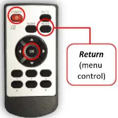
text_image
POWER I U HOME NOES OK 1 2 3 4 5 6 Return (menu control)
flowchart
graph TD
    A["FPG ON/OFF"] --> B["Funconal Parking Guidelines ON/OFF F"]
    C["PDC ON/OFF"] --> D["Parking Distance Control ON/OFF (while in reverse)"]
    E["FPG POSITION"] --> F["Adjust FPG Posion"]
    G["PDC POSITION"] --> H["Adjust PDC Posion"]
    I["WARNING ON/OFF"] --> J["'Safe to move?' ON/OFF"]
text_image
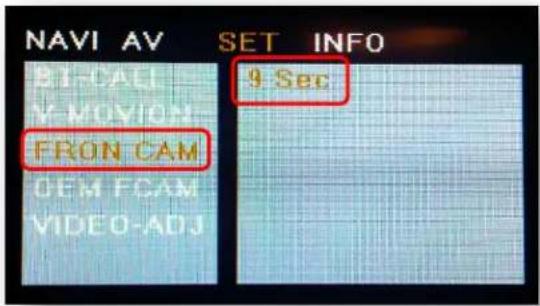
NAVI AV SET INFO BT-CALL Y-MOVION- FRON CAM OEM FCAM VIDEO-ADJ 9 SecTo enter the AUX menu, DIP SWITCH #2 must be DOWN. Press the provided momentary buon once aer connecting to module. Once 'AV1' shows on the screen, press the OK Button (remote) 4x, then press power.
SET – FRON CAM must be turned on if adding a front camera and the user wishes for automac front camera switching (displays aer leaving reverse gear).
Opons for 5, 7, 9 or 11 seconds are user selectable for the length of me the front camera input stays acve once the vehicle is placed out of reverse (OEM similar).
If the user wants only a forced AUX video input (no mer function), leave this opon 'OFF' and use DIP SWITCH 2 for adding AUX Video input, selectable via the provided push buon switch.
Adding HD-LINK Adapter (HDMI Input)
Follow the instrucons below when adding the HDMI adapter (HD-LINK) to enable HDMI input to the OEM screen:

text_image
OK 1U MUTS- Put dip switch #1 in the DOWN posion.
- Acvate the 'NAV INPUT' by pressing the provided push buon (must be connected to module).
-
Once 'NAV INPUT' shows on the screen, on the remote press the OK BUTTON 4 mes, then press POWER.
-
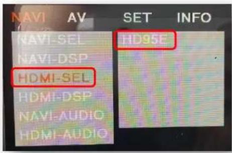
Navigate to the 'NAVI' secon.
a. Select 'HDMI-SEL'
b. Choose 'HD95E'
c. Press MODE on the remote to return and exit the OSD menu (or let it me out).
- Replace dip switch #1 to the UP posion.
- Connect the black wire to ground (-) and the red wire to ACC power (+) from the main power connector on the HD-LINK adapter. The RCA's on this plug provide audio from the HDMI source.
text_image
NAVI AV SET INFO NAVI-SEL HD95E NAVI-DSP HDMI-SEL HDMI-DSP NAVI-AUDIO HDMI-AUDIO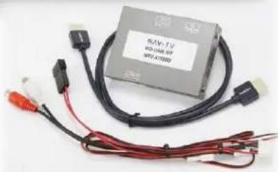
natural_image
Electronic component with black cable, red connectors, and connector pin (no visible text or symbols)Green Trigger wire setup
This module includes a green input wire for analog triggering of either the Reverse camera input or the 'AVIN' input (yellow RCAs), selectable through the AV menu. This allows for adding mulple cameras through the use of an SVS-6 switcher, etc. Follow the steps below adjust this feature. NOTE: by default, the green wire will trigger the Reverse camera input RCA.
- Put dip switch #1 in the DOWN posion. When this secon is complete, return switch #1 UP.
- Acvate the 'NAV INPUT' by pressing the push buon provided with the kit (connect to module).
-
Once 'NAV INPUT' shows on the screen, on the remote press the OK BUTTON 4 mes, then press POWER.
-
Navigate to the 'SET' secon.
○ Select 'REVERSE WIRE'
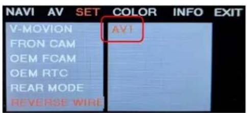
○ Choose 'AV1', 'REAR' or 'REAR MODE' (explanaons below)
- Press MODE on the remote to return and exit the OSD menu (or let it me out).
- Test by sending temporary power (12v +) to the green wire labeled reverse.
text_image
NAVI AV SET COLOR INFO EXIT V-MOVION AV1 FRON CAM OEM FCAM OEM RTC REAR MODE REVERSE WIREAV1 shows the 'AVIN' RCA when the green reverse wire is triggered.

text_image
NAVI AV SET COLOR INFO EXIT V-MOVION REAR FRON CAM OEM FCAM OEM RTC REAR MODE REVERSE WIREREAR shows the 'CAMERA' RCA (with no lines) when the green reverse wire is triggered.
text_image
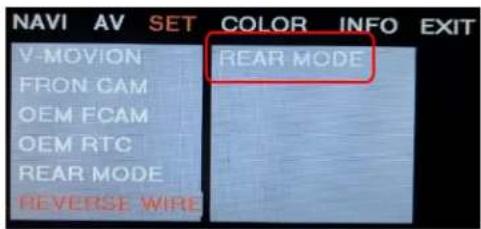
NAVI AV SET COLOR INFO EXIT V-MOVION REAR MODE FRON CAM OEM FCAM OEM RTC REAR MODE REVERSE WIREREAR MODE shows the 'CAMERA' RCA (with dynamic lines) when the green reverse wire is triggered.
Agreement: End user agrees to use this pro reverse wire is triggered. AV-TV green reverse wire is misuse of its product. If you do not agree, please discontinue use immediately and return product to place of purchase. This product is intended for off-road use and passenger entertainment only.
AUDI DYN-INT Operaon
- Once all connecons have been properly made, placing the vehicle in reverse will show the connected rear camera image with Dynamic Guidelines which correspond with the steering wheel geometry.
- If a front camera was added and Automac front-camera switching was turned on, whenever the vehicle leaves reverse (aer showing reverse image once) the connected front camera will display for the user-set amount of me (5, 7, 9 or 11 seconds).
- If no front camera switching is wanted, use the iNAV buon on the steering wheel for AUX Video switching (not supported in all vehicles). Alternatively, pressing the provided toggle switch will switch between AUX Video modes in this order: (OEM-RGB[NAVI]-AV1-AV2-OEM) when connected (dip switch dependent).
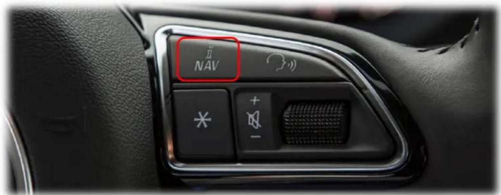
text_image
NAV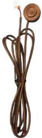
natural_image
Coiled brown cable with a circular head and bulb, no visible text or symbolsFAQs
Q. The unit will not power on, I have no indicaon of proper operaon.
A. This module will not power on properly or display anything (reverse image or AUX video IN) until CAN is properly connected.
Q. All I see on the display is a black screen (no factory image pass-through).
A. Verify the video cables (IN/OUT) are connected at the proper locaon (at the screen).
B. Verify the video cables are seated all the way.
C. Verify the Dip Switches are set correctly.
Q. Rear camera image does NOT appear.
A. Make certain Dip Switch #4 in set down for aermarket camera, or up for a factory camera.
B. Verify the CAN wires. This module uses CAN data to trigger the reverse image on the screen.
C. Make certain the camera is properly powered. Check voltage at the camera itself.
D. Try an alternate video source, don't assume the power/ground is correct unless you've checked it with a mul-meter!
E. If this is a CAN-connected module and you've connected the CAN wires, try using the green wire instead of the CAN conneccon for reverse acvaon.
Q. Unwanted A/V mode is displayed upon a toggle press (A/V source switching order: OEM->RGB->AV1->AV2->OEM).
A. Check DIP Switch Sengs. Refer to page 2.