
P3500S - Power amplifier YAMAHA - Free user manual and instructions
Find the device manual for free P3500S YAMAHA in PDF.
| Product Type | Professional 2-channel power amplifier |
| Brand | YAMAHA |
| Model | P3500S |
| Output Power (8 Ω) | 350 W per channel |
| Output Power (4 Ω) | 500 W per channel |
| Bridge Power (8 Ω) | 1000 W |
| Frequency Response | 10 Hz - 30 kHz (+0.5/-3 dB) |
| Total Harmonic Distortion (THD) | <0.05% |
| Input Impedance | 20 kΩ (balanced), 10 kΩ (unbalanced) |
| Input Sensitivity | 0.775 V (4 dBu) |
| Signal-to-Noise Ratio | >100 dB |
| Power Supply | 220-240 V AC, 50/60 Hz |
| Power Consumption | 600 W |
| Dimensions (W x H x D) | 480 x 88 x 400 mm |
| Weight | 12 kg |
| Cooling | Variable speed fan |
| Protections | Current, thermal, DC, soft start |
| Inputs | XLR and TRS balanced |
| Outputs | Screw terminals (banana plug) |
| Bridge Mode | Yes, via switch |
| Maintenance | Clean with dry cloth; avoid solvents |
| Safety | Do not open the device; unplug before maintenance |
Frequently Asked Questions - P3500S YAMAHA
User questions about P3500S YAMAHA
0 question about this device. Answer the ones you know or ask your own.
Ask a new question about this device
Download the instructions for your Power amplifier in PDF format for free! Find your manual P3500S - YAMAHA and take your electronic device back in hand. On this page are published all the documents necessary for the use of your device. P3500S by YAMAHA.
USER MANUAL P3500S YAMAHA
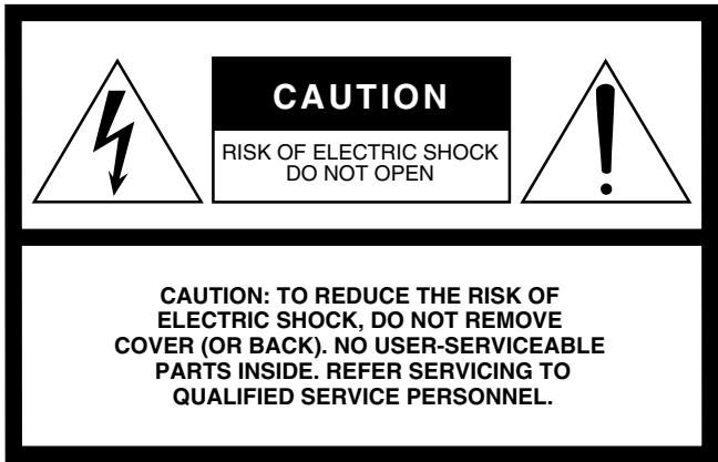
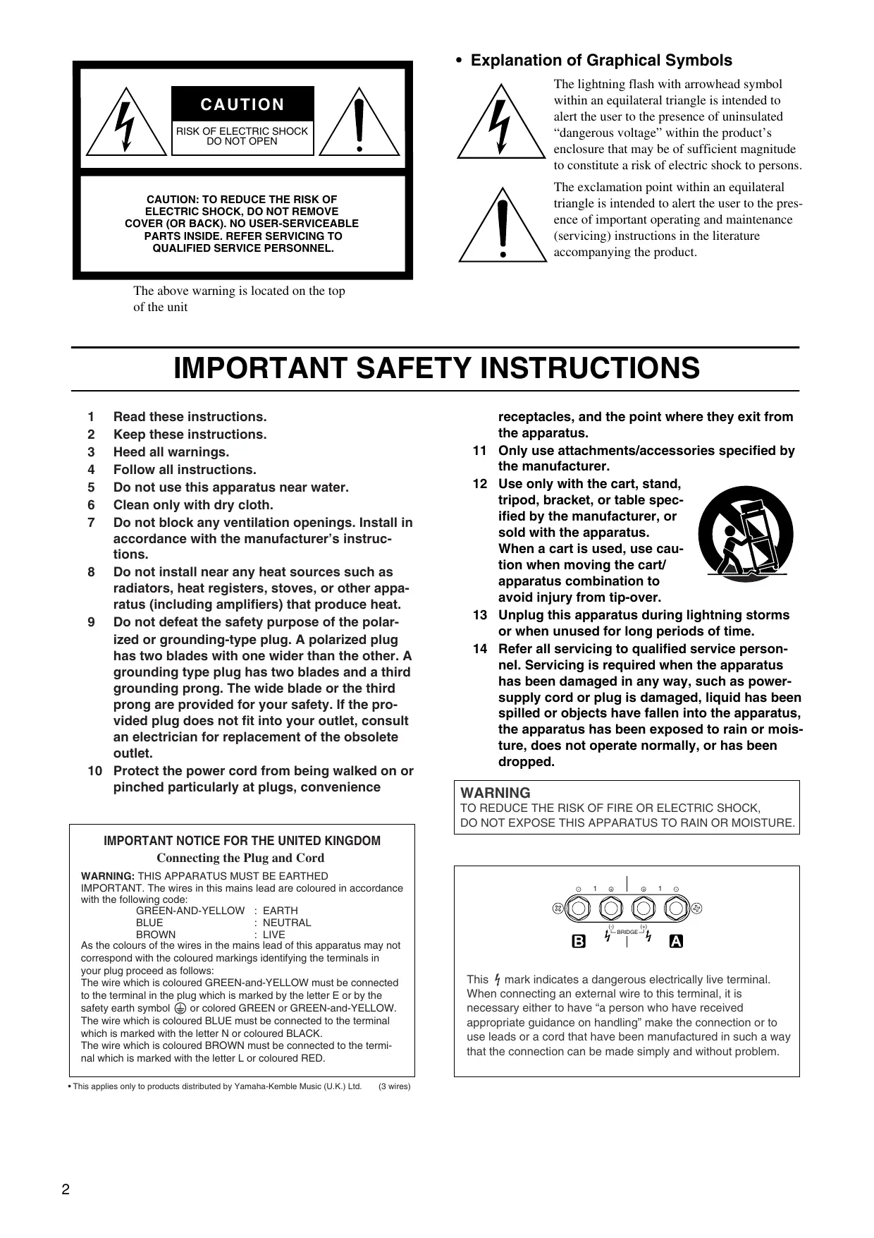
The above warning is located on the top of the unit
- Explanation of Graphical Symbols
The lightning flash with arrowhead symbol within an equilateral triangle is intended to alert the user to the presence of uninsulated "dangerous voltage" within the product's enclosure that may be of sufficient magnitude to constitute a risk of electric shock to persons.
The exclamation point within an equilateral triangle is intended to alert the user to the presence of important operating and maintenance (servicing) instructions in the literature accompanying the product.
IMPORTANT SAFETY INSTRUCTIONS
1 Read these instructions.
2 Keep these instructions.
3 Heed all warnings.
4 Follow all instructions.
5 Do not use this apparatus near water.
6 Clean only with dry cloth.
7 Do not block any ventilation openings. Install in accordance with the manufacturer's instructions.
8 Do not install near any heat sources such as radiators, heat registers, stoves, or other apparatus (including amplifiers) that produce heat.
9 Do not defeat the safety purpose of the polarized or grounding-type plug. A polarized plug has two blades with one wider than the other. A grounding type plug has two blades and a third grounding prong. The wide blade or the third prong are provided for your safety. If the provided plug does not fit into your outlet, consult an electrician for replacement of the obsolete outlet.
10 Protect the power cord from being walked on or pinched particularly at plugs, convenience
IMPORTANT NOTICE FOR THE UNITED KINGDOM
Connecting the Plug and Cord
WARNING: THIS APPARATUS MUST BE EARTHED
IMPORTANT. The wires in this mains lead are coloured in accordance with the following code:
GREEN-AND-YELLOW : EARTH
BLUE : NEUTRAL
BROWN : LIVE
As the colours of the wires in the mains lead of this apparatus may not correspond with the coloured markings identifying the terminals in your plug proceed as follows:
The wire which is coloured GREEN-and-YELLOW must be connected to the terminal in the plug which is marked by the letter E or by the safety earth symbol ⑤ or colored GREEN or GREEN-and-YELLOW.
The wire which is coloured BLUE must be connected to the terminal which is marked with the letter N or coloured BLACK.
The wire which is coloured BROWN must be connected to the terminal which is marked with the letter L or coloured RED.
This applies only to products distributed by Yamaha-Kemble Music (U.K.) Ltd. (3 wires)
receptacles, and the point where they exit from the apparatus.
11 Only use attachments/accessories specified by the manufacturer.
12 Use only with the cart, stand, tripod, bracket, or table specified by the manufacturer, or sold with the apparatus.

When a cart is used, use caution when moving the cart/ apparatus combination to avoid injury from tip-over.
13 Unplug this apparatus during lightning storms or when unused for long periods of time.
14 Refer all servicing to qualified service personnel. Servicing is required when the apparatus has been damaged in any way, such as power-supply cord or plug is damaged, liquid has been spilled or objects have fallen into the apparatus, the apparatus has been exposed to rain or moisture, does not operate normally, or has been dropped.
WARNING
TO REDUCE THE RISK OF FIRE OR ELECTRIC SHOCK, DO NOT EXPOSE THIS APPARATUS TO RAIN OR MOISTURE.
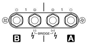
This mark indicates a dangerous electrically live terminal. When connecting an external wire to this terminal, it is necessary either to have "a person who have received appropriate guidance on handling" make the connection or to use leads or a cord that have been manufactured in such a way that the connection can be made simply and without problem.
— For safe operation —
WARNING
Installation
- Connect this unit's power cord only to an AC outlet of the type stated in this Owner's Manual or as marked on the unit. Failure to do so is a fire and electrical shock hazard.
- Do not allow water to enter this unit or allow the unit to become wet. Fire or electrical shock may result.
- Do not place a container with liquid or small metal objects on top of this unit. Liquid or metal objects inside this unit are a fire and electrical shock hazard.
- Do not place heavy objects, including this unit, on top of the power cord. A damaged power cord is a fire and electrical shock hazard. In particular, be careful not to place heavy objects on a power cord covered by a carpet.
- Be sure to connect to an appropriate outlet with a protective grounding connection. Improper grounding can result in electrical shock.
Operation
- Do not scratch, bend, twist, pull, or heat the power cord. A damaged power cord is a fire and electrical shock hazard.
-
Do not remove the unit's cover. You could receive an electrical shock. If you think internal inspection, maintenance, or repair is necessary, contact your dealer.
-
Do not modify the unit. Doing so is a fire and electrical shock hazard.
- If lightning begins to occur, turn off the power switch of the unit as soon as possible, and unplug the power cable plug from the electrical outlet.
- If there is a possibility of lightning, do not touch the power cable plug if it is still connected. Doing so may be an electrical shock hazard.
In case an abnormality occurs during operation
- If the power cord is damaged (i.e., cut or a bare wire is exposed), ask your dealer for a replacement. Using the unit with a damaged power cord is a fire and electrical shock hazard.
- Should this unit be dropped or the cabinet be damaged, turn the power switch off, remove the power plug from the AC outlet, and contact your dealer. If you continue using the unit without heeding this instruction, fire or electrical shock may result.
- If you notice any abnormality, such as smoke, odor, or noise, or if a foreign object or liquid gets inside the unit, turn it off immediately. Remove the power cord from the AC outlet. Consult your dealer for repair. Using the unit in this condition is a fire and electrical shock hazard.
CAUTION
Installation
-
Keep this unit away from the following locations:
-
Locations exposed to oil splashes or steam, such as near cooking stoves, humidifiers, etc.
- Unstable surfaces, such as a wobbly table or slope.
- Locations exposed to excessive heat, such as inside a car with all the windows closed, or places that receive direct sunlight.
-
Locations subject to excessive humidity or dust accumulation.
-
Do not place the power cord close to a heater. It may melt, causing fire or electrical shock.
- Hold the power cord plug when disconnecting it from an AC outlet. Never pull the cord. A damaged power cord is a potential fire and electrical shock hazard.
- Do not touch the power plug with wet hands. Doing so is a potential electrical shock hazard.
-
This unit has ventilation holes at the front and rear to prevent the internal temperature rising too high. Do not block them. Restricted ventilation holes are a fire hazard. In particular, do not
-
place the unit on its side or upside down,
- place the unit in any poorly-ventilated location such as a book-case or closet (other than on the dedicated rack),
-
cover the unit with a table cloth or place it on a carpet or bed.
-
Allow enough free space around the unit for normal ventilation. This should be: 5cm at the sides, 10cm behind, and 10cm above. If the airflow is not adequate, the unit will heat up inside and may cause a fire.
-
To mount several of these units in a standard EIA rack, refer to the rack mounting instructions on page 11.
-
To relocate the unit, turn the power switch off, remove the power plug from the AC outlet, and remove all connecting cables. Damaged cables may cause fire or electrical shock.
- When setting up the product, make sure that the AC outlet you are using is easily accessible. If some trouble or malfunction occurs, immediately turn off the power switch and disconnect the plug from the outlet. Even when the power switch is turned off, electricity is still flowing to the product at the minimum level. When you are not using the product for a long time, make sure to unplug the power cord from the wall AC outlet.
- Do not place the device in a location where it may come into contact with corrosive gases or salt air. Doing so may result in malfunction.
Operation
- Use only speaker cables when connecting speakers to amplifier outputs. Using other types of cables is a fire hazard.
- Turn off all musical instruments, audio equipment, and speakers when connecting to this unit. Use the correct connecting cables and connect as specified.
- Always lower the volume control to minimum before turning on the power to this unit. A sudden blast of sound may damage your hearing.
- Do not use this amplifier for any purpose other than driving loudspeakers.
- If you know you will not use this unit for a long period of time, such as when going on vacation, remove the power plug from the AC outlet. Leaving it connected is a potential fire hazard.
— For correct operation —
Connector pin assignments
- XLR-type connectors are wired as follows
Pin 1: ground; Pin 2: hot (+); Pin 3: cold (-).
Interference from Cell Phones
- Use of a mobile phone near this unit may induce noise. If noise occurs, move the phone further from the unit.
Always turn the power off when the amplifier is not in use.
Illustrations in this manual are for explanatory purposes only, and may not match the actual appearance of the product during operation.
Company names and product names used in this Owner's Manual are trademarks or registered trademarks of their respective owners.
FCC INFORMATION (U.S.A.)
1. IMPORTANT NOTICE: DO NOT MODIFY THIS UNIT!
This product, when installed as indicated in the instructions contained in this manual, meets FCC requirements. Modifications not expressly approved by Yamaha may void your authority, granted by the FCC, to use the product.
-
IMPORTANT: When connecting this product to accessories and/or another product use only high quality shielded cables. Cable/s supplied with this product MUST be used. Follow all installation instructions. Failure to follow instructions could void your FCC authorization to use this product in the USA.
-
This applies only to products (P7000S, P5000S) distributed by YAMAHA CORPORATION OF AMERICA.
Thank you for your purchase of the YAMAHA P7000S, P5000S, P3500S or P2500S power amplifier. These P-series amplifiers fully incorporate Yamaha's renown technological expertise, and offer high reliability, rock-solid stability, and superb acoustic characteristics—all in a trim, 2U-sized package.
Features
- With two types of input jacks (balanced XLR and balanced phone) and three types of output jacks (Speakon, 5-way binding post, and phone), the P series is suitable for a wide variety of applications and installed systems.
- The unit offers three operating modes: STEREO (where Channels A and B operate independently), PARALLEL (where the unit outputs a mono source through twin amplifier systems), and BRIDGE (where the unit operates as a single high-power amp).
- Each channel is equipped with an independent OFF/LOW CUT/SUBWOOFER switch—where LOW CUT engages a high-pass filter, and SUBWOOFER engages a low-pass filter. With LOW CUT or SUBWOOFER selected, you can adjust the cutoff frequency from 25 to 150Hz .
Each channel has its own SIGNAL and CLIP indicators. - The PROTECTION indicator lights up—and sound output is automatically muted—whenever the unit's protective circuitry is operating. The TEMP indicator lights up if the unit is running hot.
- Variable-speed low-noise fans ensure high reliability.
This Owner's Manual covers the four models: P7000S, P5000S, P3500S and P2500S power amplifiers. Please read through this manual carefully before beginning use, so that you will be able to take full advantage of the amplifier's superlative features and enjoy trouble-free operation for years to come. After reading through the manual, please store it in a safe place.
Contents
Controls and Functions 6
Front Panel 6
Rear Panel 7
Speaker Connections 9
Speaker impedance 9
Wiring 10
Rack Mounting 11
Specifications 12
General Specifications 12
Block Diagram 13
Dimensions 14
Current Draw 14
Troubleshooting 15
■ Front Panel
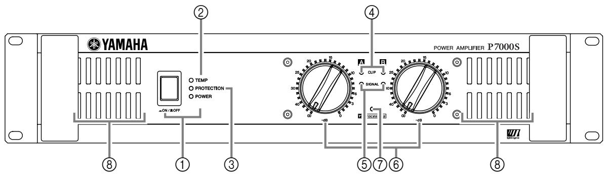
① POWER switch and indicator
Press to toggle the power on or off. The POWER indicator lights up green when the power is ON.
② TEMPindicator
Lights up red if the heat sink temperature exceeds 85^ (185^) .
③ PROTECTION indicator
Lights up red to indicate that protection is in effect. Specifically, lights up if the heat sink overheats, or if a DC voltage is detected at the amplifier outputs. Also lights up for about three seconds at time of power-on, as the amp gets ready to operate. To provide protection, the unit will not output any sound from the speakers while this indicator is lit up. When start-up is completed or the problem is corrected, the indicator goes off and normal operation resumes.
④ CLIP indicator
Lights up red when the output signal distortion on the corresponding channel rises above 1% -indicating that "clipping" has occurred because the signal level is too high.
⑤ SIGNAL indicator
Lights up green when the corresponding channel's output level exceeds 2 Vrms (equivalent to 1/2W into an 8 load, or 1W into a 4 load).
⑥ Volume control knobs
Each control knob adjusts the volume of the corresponding channel, in 31 steps from - dB to 0dB
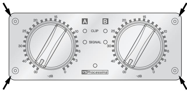
NOTE:
If you wish to lock in the knob settings, you can fasten the supplied security cover over the knobs so that the settings will not be disturbed.
How to install the security cover
(1) Use the supplied hex wrench to remove the four attachment screws from the amplifier.
(2) Adjust the security cover to the position of screw holes. Fasten it into place using the same screws.
⑦ YSProcessing indicator
Lights up yellow if the YS PROCESSING switch on the rear panel is set ON. (See page 7.)
⑧ Air intakes
The amplifier uses forced-air cooling. The cooling fans draw air in from the front and exhaust it through the rear. Please be sure that you do not block the air intakes or exhaust vents.
NOTE:
The fans do not come on at initial power-on, but will switch on automatically when the temperature of the heat sink rises above 50^ (122^) . The fan speed will then vary automatically as the temperature changes.
Rear Panel
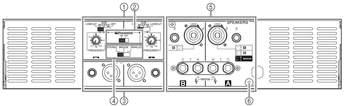
① FILTER switch and FREQUENCY adjustment knob (One pair for each channel)
Use these controls to select the filter type and adjust the cutoff frequency on each channel (A and B). You use the FILTER switch to select the filter, as follows.

OFF............ Do not use any filter.
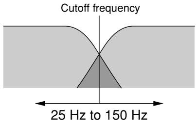
SUBWOOFER.... Use a low-pass filter. The amplifier outputs the frequencies that are lower than the cutoff set by the FREQUENCY adjustment knob.
LOW CUT ........ Use a high-pass filter. You can use this setting to filter out unneeded low or subsonic frequencies.
If you select SUBWOOFER or LOW CUT, you can then use the FREQUENCY adjustment knob to adjust the cutoff frequency. The adjustment range is 25Hz to 150Hz .
NOTE:
If the amplifier is set to BRIDGE mode, only the switch and knob for Channel A are effective. (The Channel B frequency controls are disabled.)
② YSProcessing ON/OFF switch
If you set this switch ON, the amplifier adds low-frequency compensation so as to enhance speaker output. The results (the actual change in the low-frequency balance) will vary according to the speaker type. Note that this switch is effective only if the FILTER switch is set to OFF.
NOTE:
This feature provides improved frequency reponse on speakers such as the YAMAHA S112 and S115.
③ INPUT jacks (Channels A, B)
Two jack types are provided for each channel. Note that if you are using BRIDGE or PARALLEL mode, only the Channel A jacks are effective.
- XLR-3-31 jack
The XLR-3-31 input jacks are wired as shown below.

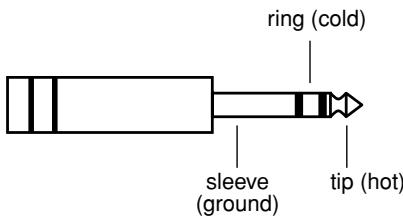
- Phone jack
Phone jacks are wired as follows.
④ STEREO/PARALLEL/BRIDGE switch
Use this switch to select the operating mode.
- STEREO mode
Channels A and B operate independently (as with a conventional stereo amplifier). The Channel A input goes to the Channel A output jacks, and the Channel B input goes to the Channel B output jacks.
PARALLEL mode
The Channel A input signal is output through both the Channel A and Channel B output jacks. The Channel B input jacks do not function. Channel A and B volumes can be independently adjusted.
BRIDGE mode
The Channel A input signal is output from the BRIDGE output jacks. To adjust the volume, you must use the Channel A volume control knob.
⑤ SPEAKER jacks
Neutrik NL4FC Speakon output connectors,
5-way binding post output jacks,
Phone output jacks
For minimum speaker impedence values, see page 9.
⑥ GND terminal
This is a screw-type ground terminal. If you are having a problem with hum or noise, use this terminal to connect to ground or to connect to the chassis of the mixer, preamp, or other device in your system.
■ Speaker impedance
Speakers can be connected to the amplifier as shown below. Note that speaker impedance will vary according to the connection method and the number of speakers. Please be sure that your speakers' impedance is not less than the relevant minimum value indicated below.
Connection configurations for STEREO and PARALLEL modes
When using 5-way binding post output jacks
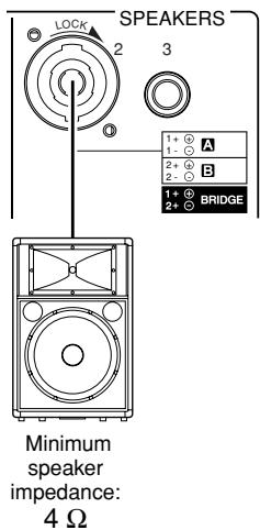
When using Speakon connector
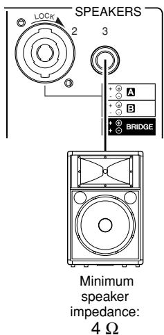
When using phone jack
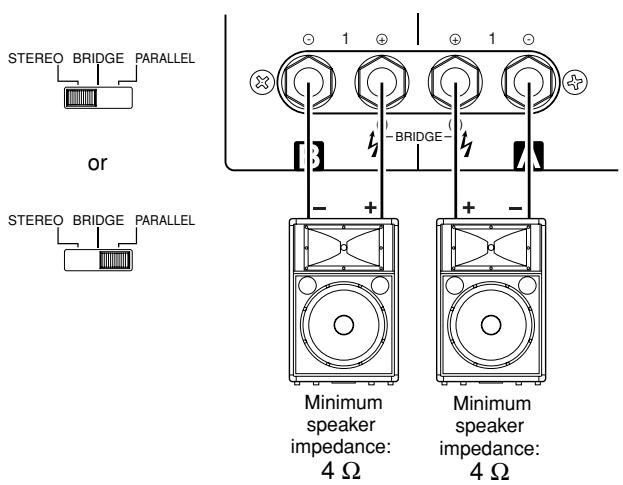
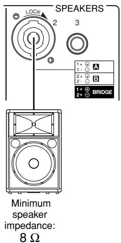
Connection configurations for BRIDGE mode
When using 5-way binding post output jacks
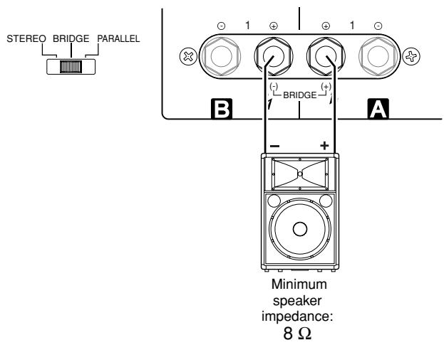
When using Speakon connector
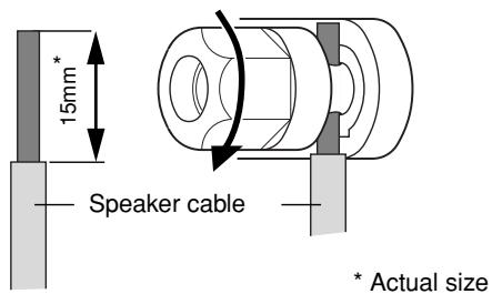
■ Wiring
5-way binding post
(1) Turn off the POWER switch.
(2) Remove the cover attachment screws and remove the protective cover from the speaker terminals.

(3) Remove about 15mm of insulation from the end of each speaker cable, and pass the bare wire through the holes in the appropriate speaker terminals. Tighten the terminals to securely clamp the wires. Refer to page 9 for speaker polarities.
Note to users in the USA:
Please use Class 3 wiring. (P7000S, P5000S)
Please use Class 2 wiring. (P3500S, P2500S)
Be sure that the bare wire ends do not jut out from the terminals and touch the chassis. The following shows how the cable should look when correctly attached.
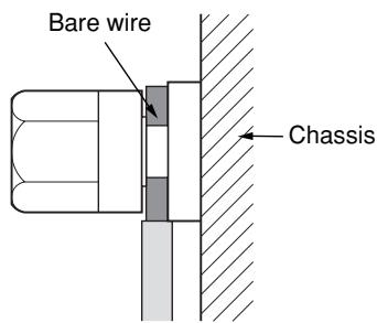
(4) Reattach the protective cover over the speaker terminals.
Speakon connector
(1) Turn off the POWER switch.
(2) Insert the Neutrik NL4FC plugs into the Speakon connector on the rear of the amplifier, and turn clockwise to lock.
Neutrik NL4FC plugs
| CHANNEL A STEREO or PARALLEL BRIDGE | |
| 1+ | A+ |
| 1- | A- |
| 2+ | B+ |
| 2- | B- |
| CHANNEL B | |
| 1+ | B+ |
| 1- | B- |
Phone jack
(1) Turn off the POWER switch.
(2) Insert the phone plug into the jack on the rear of the amplifier.
Mounting in a standard EIA rack
If you are mounting multiple power amplifiers in a rack, be sure to install ventilation panel(s) as shown below. Also be sure to use metal brackets (one on each side) to support the rear of each amplifier.
Note: EIA stands for Electronic Industries Alliance.
Ventilation panel(s)
Use 1U-size blank panel(s).
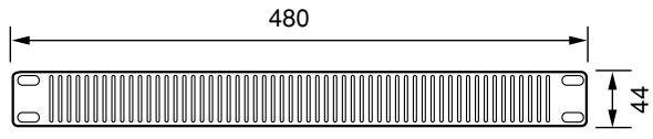
Unit: mm
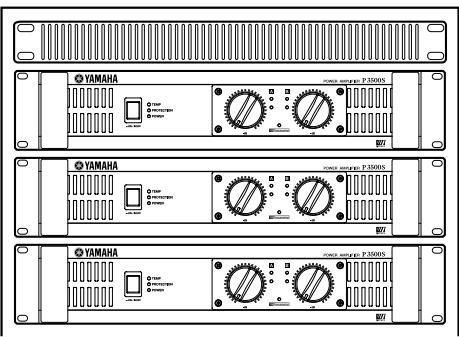
If mounting up to four amplifiers in an open-backed rack
Install a ventilation panel as shown below.
Ventilation panel (Attach to the front or rear of the rack.)
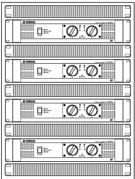
When mounting five or more amplifiers in an open-backed rack, and when mounting any number of amplifiers in a close-backed rack
Install ventilation panels above and below each amplifier, as shown below.
General Specifications
| P7000S | P5000S | P3500S | P2500S | ||
| Power Output Level (Rated Power) | 8 Ω/STEREO | 750 W × 2 | 525 W × 2 | 390 W × 2 | 275 W × 2 |
| 1 kHz | 4 Ω/STEREO | 1100 W × 2 | 750 W × 2 | 590 W × 2 | 390 W × 2 |
| THD + N = 1% | 8 Ω/BRIDGE | 2200 W × 1 | 1500 W × 1 | 1180 W × 1 | 780 W × 1 |
| 8 Ω/STEREO | 700 W × 2 | 500 W × 2 | 350 W × 2 | 250 W × 2 | |
| 650 W × 2 (European Model) | |||||
| 20 Hz - 20 kHz | 4 Ω/STEREO | 950 W × 2 | 700 W × 2 | 450 W × 2 | 310 W × 2 |
| THD + N = 0.1% | 8 Ω/BRIDGE | 1900 W × 1 | 1400 W × 1 | 900 W × 1 | 620 W × 1 |
| 1 kHz | 2 Ω/STEREO | 1600 W × 2 | 1300 W × 2 | 1000 W × 2 | 650 W × 2 |
| 20 ms non-clip | 4 Ω/BRIDGE | 3200 W × 1 | 2600 W × 1 | 2000 W × 1 | 1300 W × 1 |
| Power Bandwidth | Half Power | 10 Hz - 40 kHz (THD + N = 0.5%) | |||
| Total Harmonic Distortion (THD + N) | 4 Ω - 8 Ω/STEREO | ≤ 0.1% | |||
| 20 Hz - 20 kHz, Half Power | 8 Ω/BRIDGE | ||||
| Frequency Response | RL = 8 Ω, Po = 1 W | 0 dB, +0.5 dB, -1 dB f = 20 Hz - 50 kHz | |||
| Intermodulation distortion (IMD) | 4 Ω - 8 Ω/STEREO | ≤ 0.1% | |||
| 60 Hz:7 kHz, 4:1, Half Power | 8 Ω/BRIDGE | ||||
| Channel Separation | Half Power RL = 8 Ω 1 kHz input 600 Ω shunt | ≥ 70 dB | |||
| Vol. max | |||||
| Residual Noise Vol. min. | 20 Hz - 20 kHz (DIN AUDIO) | ≤ -70 dB | |||
| SN Ratio | 20 Hz - 20 kHz (DIN AUDIO) | 104 dB | 103 dB | 102 dB | 100 dB |
| Damping Factor | RL = 8 Ω, 1 kHz | ≥ 350 | ≥ 200 | ||
| Sensitivity (Vol. max.) Rated Power 8 Ω | +8 dBu | +6 dBu | +4 dBu | +3 dBu | |
| Voltage Gain (Vol. max.) | 32.1 dB | ||||
| Input Impedance | 30 kΩ/balanced, 15 kΩ/unbalanced | ||||
| Controls | Front Panel | POWER switch (Push on/Push off)Two 31-step Volume control knobs (one per ch) | |||
| Rear Panel | MODE switch (STEREO/PARALLEL/BRIDGE)Two FILTER switches (SUBWOOFER/LOW CUT/OFF)Two fc knobs (25 to 150 Hz, 12 dB/octave)YS Processing switch (ON/OFF) | ||||
| Connectors | INPUT | XLR-3-31 jacks (one per ch)1/4-inch TRS phone jacks (one per ch) | |||
| OUTPUT | Speakon jacks (one per ch)5-way binding posts1/4-inch phone jacks (one per ch) | ||||
| Indicators | POWER | ×1 (Green)×1 (Red) | |||
| PROTECTION | ×1 (Red) (heatsink temp ≥ 85°C) | ||||
| TEMP | ×2 (Red) | ||||
| CLIP | ×2 (Green) | ||||
| SIGNAL | ×1 (Yellow) | ||||
| YS Processing | |||||
| Load protection | POWER switch ON/OFF muting | ||||
| DC-fault power supplyshutdown | DC detection | ||||
| Amp. protection | Temp. detection (heat sink temp ≥ 90°C), VI limiter (RL ≤ 1 Ω) | ||||
| Limiter | Comp: THD ≥ 0.5% | ||||
| Cooling | Dual variable-speed fan | Single variable-speed fan | |||
| Power Requirements | United States & Canada | 120 V, 60 Hz | |||
| Europe | 230 V, 50 Hz | ||||
| Australia | 240 V, 50 Hz | ||||
| Power Consumption | Idling | 35 W | 35 W | 30 W | 25 W |
| Output power, 4 Ω | 650 W | 500 W | 450 W | 320 W | |
| Dimensions (W × H × D) | 480 × 88 × 456 mm | ||||
| Weight | 12 kg | 12 kg | 15 kg | 14 kg | |
| Included Accessories | Security cover (with a hex wrench), Owner's Manual | ||||
0 dBu=0.775 Vrms, Half Power=1/2 Power Output Level (Rated Power)
Specifications and descriptions in this owner's manual are for information purposes only. Yamaha Corp. reserves the right to change or modify products or specifications at any time without prior notice. Since specifications, equipment or options may not be the same in every locale, please check with your Yamaha dealer.
European models
Purchaser/User Information specified in EN55103-1 and EN55103-2.
Inrush Current: 25A (P7000S, P5000S)/66A (P3500S)/68A (P2500S)
Conforms to Environments: E1, E2, E3 and E4
■ Block Diagram
P7000S, P5000S
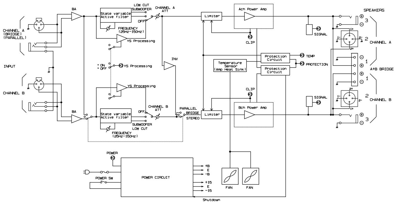
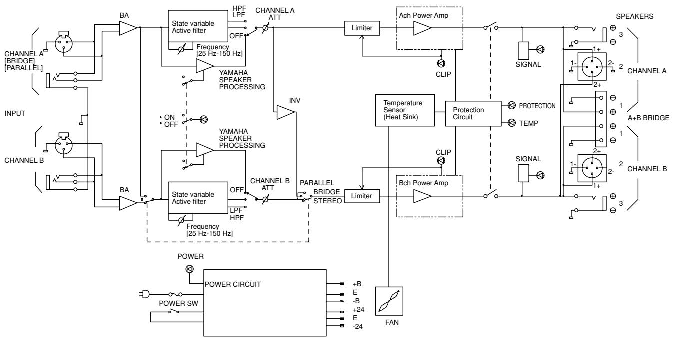
P3500S, P2500S
Dimensions
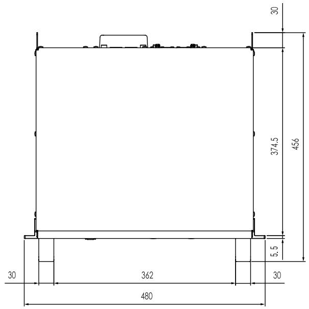
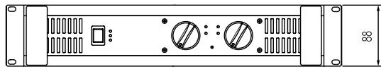
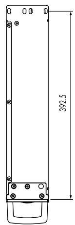
Unit: mm
Current Draw
P7000S
| Line Current (A) | Power (W) | Thermal Dissipation | ||||||
| 100/120V | 230/240V | In | Out | Dissipated | Btu/h | kcal/h | ||
| standby | 0.08 | 0.04 | 5 | 0 | 5 | 17 | 4 | |
| idle | 1.0 | 0.5 | 35 | 0 | 35 | 119 | 30 | |
| 1/8 power | 8Ω/ch | 5.4 | 3.0 | 379 | 188 | 191 | 653 | 165 |
| 4Ω/ch | 8.5 | 4.7 | 611 | 275 | 336 | 1150 | 289 | |
| 1/3 power | 8Ω/ch | 12.8 | 7.0 | 918 | 500 | 418 | 1430 | 360 |
| 4Ω/ch | 20.6 | 11.3 | 1481 | 733 | 748 | 2550 | 643 | |
P5000S
| Line Current (A) | Power (W) | Thermal Dissipation | ||||||
| 100/120V | 230/240V | In | Out | Dissipated | Btu/h | kcal/h | ||
| standby | 0.08 | 0.04 | 5 | 0 | 5 | 17 | 4 | |
| idle | 1.0 | 0.5 | 35 | 0 | 35 | 119 | 30 | |
| 1/8 power | 8Ω/ch | 4.0 | 2.2 | 277 | 131 | 146 | 499 | 126 |
| 4Ω/ch | 6.2 | 3.4 | 436 | 188 | 249 | 848 | 214 | |
| 1/3 power | 8Ω/ch | 9.3 | 5.1 | 673 | 350 | 323 | 1100 | 278 |
| 4Ω/ch | 14.7 | 8.1 | 1057 | 500 | 557 | 1900 | 479 | |
P3500S
| Line Current (A) | Power (W) | Thermal Dissipation | ||||||
| 100/120V | 230/240V | In | Out | Dissipated | Btu/h | kcal/h | ||
| standby | 0.08 | 0.04 | 5 | 0 | 5 | 17 | 4 | |
| idle | 1.0 | 0.5 | 30 | 0 | 30 | 102 | 26 | |
| 1/8 power | 8Ω/ch | 3.2 | 1.7 | 227 | 98 | 130 | 443 | 112 |
| 4Ω/ch | 5.0 | 2.8 | 378 | 148 | 231 | 787 | 198 | |
| 1/3 power | 8Ω/ch | 7.3 | 4.0 | 551 | 260 | 291 | 993 | 250 |
| 4Ω/ch | 12.2 | 6.7 | 917 | 393 | 524 | 1790 | 450 | |
P2500S
| Line Current (A) | Power (W) | Thermal Dissipation | ||||||
| 100/120V | 230/240V | In | Out | Dissipated | Btu/h | kcal/h | ||
| standby | 0.08 | 0.04 | 5 | 0 | 5 | 17 | 4 | |
| idle | 1.0 | 0.5 | 25 | 0 | 25 | 85 | 22 | |
| 1/8 power | 8Ω/ch | 2.4 | 1.3 | 174 | 69 | 105 | 358 | 90 |
| 4Ω/ch | 3.6 | 2.0 | 271 | 98 | 173 | 592 | 149 | |
| 1/3 power | 8Ω/ch | 5.6 | 3.1 | 421 | 183 | 238 | 811 | 204 |
| 4Ω/ch | 8.8 | 4.8 | 657 | 260 | 397 | 1350 | 341 | |
1/8 power is typical of program material with occasional clipping. Refer to these figures for most applications.
1/3 power represents program material with extremely heavy clipping.
Test signal: Pink Noise, bandwidth limited from 22Hz to 22kHz
1W = 0.860kcal / h 1BTU = 0.252kcal
Note that Line Voltage [V] x Line Current [A] = [VA] not equals to [W].
Inrush current
P7000S, P5000S: 11A (100V), 13A (120V), 25A (240V)
P3500S: 71A (100V), 87A (120V), 66A (240V)
P2500S: 103A (100V), 150A (120V), 68A (240V)
Troubleshooting
The following table lists the main causes of abnormal operation and the corrective measures required, as well as the protective circuit operation in each case.
| Indicator(s) | Possible Cause | Remedy | Protection Circuit |
| CLIP indicator lights. | There is a short at a speaker terminal, amplifier terminal, or wire. | Locate and correct the cause of the short. | The PC limiter circuit operates to protect the power transistors. |
| The amplifier load is excessive. | Use a speaker system with an impedance of at least 4 Ω (STEREO/PARALLEL mode) or 8 Ω (BRIDGE mode). | ||
| TEMP indicator lights. | The heat sink temperature has exceeded 85°C (185°F). | Check the ventilation slots, and provide better airflow around the amplifier. | The TEMP indicator lights up to indicate temperature warning. |
| PROTECTION indicator lights. | The heat sink temperature has exceeded 95°C (203°F). | Check the amplifier ventilation conditions and take appropriate measures to improve the airflow around the amplifier. | The thermal protection circuit operates to protect the power transistors. |
P3500S, P2500S
| Indicator(s) | Possible Cause | Remedy | Protection Circuit |
| PROTECTION indicator lights. | A DC voltage of ±2 V or greater was generated in the power amplifier's output circuit. | Consult your dealer or the nearest Yamaha service center. | The relay operates to protect the speaker system. |
P7000S, P5000S
| Indicator(s) | Possible Cause | Remedy | Protection Circuit |
| Power has been shut down. (All indicators are off.) | A DC voltage of ±2 V or greater was generated in the power amplifier's output circuit. | Consult your dealer or the nearest Yamaha service center. | The protection circuitry shut off the power to protect the speaker system. |
For details of products, please contact your nearest Yamaha representative or the authorized distributor listed below.
Yamaha Canada Music Ltd.
135 Milner Avenue, Scarborough, Ontario,
M1S 3R1, Canada
Tel: 416-298-1311
U.S.A.
Yamaha Corporation of America
6600 Orangethorpe Ave., Buena Park, Calif. 90620,
U.S.A.
Tel: 714-522-9011
CENTRAL & SOUTH AMERICA
MEXICO
Yamaha de Mexico S.A. de C.V.
Calz.Javier Rojo Gomez #1149
Col. Guadalupe del Moral
C.P.09300, Mexico,D.F.,Mexico
Tel: 55-5804-0600
BRAZIL
Yamaha Musical do Brasil Ltda.
Rua Joaquim Floriano, 913 - 4' andar, Itaim Bibi,
CEP 04534-013 Sao Paulo, SP. BRAZIL
Tel: 011-3704-1377
ARGENTINA
Yamaha Music Latin America, S.A.
Sucursal de Argentina
Olga Cossettini 1553, Piso 4 Norte
Madero Este-C1107CEK
Buenos Aires, Argentina
Tel: 011-4119-7000
PANAMA AND OTHER LATIN
AMERICAN COUNTRIES/
CARIBBEAN COUNTRIES
Yamaha Music Europe GmbH
Branch Switzerland in Zurich
Seefeldstrasse 94, 8008 Zurich, Switzerland
Tel: 01-383 3990
AUSTRIA
Yamaha Music Europe GmbH Branch Austria
Schleiergasse 20, A-1100 Wien, Austria
Tel: 01-60203900
CZECH REPUBLIC/SLOVAKIA/
HUNGARY/SLOVENIA
Yamaha Music Europe GmbH Branch Austria
Schleiergasse 20, A-1100 Wien, Austria
Tel: 01-602039025
POLAND
YS Copenhagen Liaison Office
Generatorvej 6A, DK-2730 Herlev, Denmark
Tel: 44 92 49 00
NORWAY
Yamaha Music (Russia)
Office 4015, entrance 2, 21/5 Kuznetskii
Most street, Moscow, 107996, Russia
Tel: 495 626 0660
OTHER EUROPEAN COUNTRIES
Yamaha Music Europe GmbH
Siemensstraße 22-34, 25462 Rellingen, Germany
Tel: +49-4101-3030
AFRICA
Yamaha Corporation,
Asia-Pacific Music Marketing Group
Nakazawa-cho 10-1, Naka-ku, Hamamatsu,
Japan 430-8650
Tel: +81-53-460-2313
MIDDLE EAST
TURKEY/CYPRUS
Yamaha Music Europe GmbH
Siemensstraße 22-34, 25462 Rellingen, Germany
Tel: 04101-3030
OTHER COUNTRIES
Yamaha Music Gulf FZE
LOB 16-513, P.O.Box 17328, Jubel Ali,
Dubai, United Arab Emirates
Tel: +971-4-881-5868
ASIA
THE PEOPLE'S REPUBLIC OF CHINA
Yamaha Music & Electronics (China) Co.,Ltd.
2F, Yunhedasha, 1818 Xinzha-lu, Jingan-qu,
Shanghai, China
Tel: 021-6247-2211
INDIA
Yamaha Music India Pvt. Ltd.
5F Ambience Corporate Tower Ambience Mall Complex
Ambience Island, NH-8, Gurgaon-122001, Haryana, India
Tel: 0124-466-5551
INDONESIA
PT. Yamaha Music Indonesia (Distributor)
PT. Nusantik
Gedung Yamaha Music Center, Jalan Jend. Gatot
SubROTO Kav. 4, Jakarta 12930, Indonesia
Tel: 21-520-2577
KOREA
Yamaha Music Korea Ltd.
8F, 9F, Dongsung Bldg. 158-9 Samsung-Dong,
Kangnam-Gu, Seoul, Korea
Tel: 080-004-0022
MALAYSIA
Yamaha Music Malaysia, Sdn., Bhd.
Lot 8, Jalan Perbandaran, 47301 Kelana Jaya,
Petaling Jaya, Selangor, Malaysia
Tel: 3-78030900
SINGAPORE
Yamaha Music Asia Pte., Ltd.
03-11 A-Z Building
140 Paya Lebor Road, Singapore 409015
Tel: 747-4374
TAIWAN
Yamaha KHS Music Co., Ltd.
3F, #6, Sec.2, Nan Jing E. Rd. Taipei.
Taiwan 104, R.O.C.
Tel: 02-2511-8688
THAILAND
Siam Music Yamaha Co., Ltd.
4, 6, 15 and 16^th floor, Siam Motors Building,
891/1 Rama 1 Road, Wangmai
Pathumwan, Bangkok 10330, Thailand
Tel: 02-215-2626
OTHER ASIAN COUNTRIES
Yamaha Corporation,
Asia-Pacific Music Marketing Group
Nakazawa-cho 10-1, Naka-ku, Hamamatsu,
Japan 430-8650
Tel: +81-53-460-2317
OCEANIA
AUSTRALIA
Yamaha Music Australia Pty. Ltd.
Level 1, 99 Queensbridge Street, Southbank,
Victoria 3006, Australia
Tel: 3-9693-5111
COUNTRIES AND TRUST
TERRITORIES IN PACIFIC OCEAN
Yamaha Corporation,
Asia-Pacific Music Marketing Group
Nakazawa-cho 10-1, Naka-ku, Hamamatsu,
Japan 430-8650
Tel: +81-53-460-2313
HEAD OFFICE
Yamaha Corporation, Pro Audio & Digital Musical Instrument Division
Nakazawa-cho 10-1, Naka-ku, Hamamatsu, Japan 430-8650
Tel: +81-53-460-2441
Yamaha Pro Audio global web site
http://www.yamahaproaudio.com/
Yamaha Manual Library