
DTX-900 - Electronic drum YAMAHA - Free user manual and instructions
Find the device manual for free DTX-900 YAMAHA in PDF.

| Product type | Electronic drum module |
| Brand | Yamaha |
| Model | DTX-900 |
| Dimensions (W x D x H) | approx. 482 x 227 x 98 mm |
| Weight | approx. 2.3 kg |
| Power supply | AC adapter (12 V DC, 1.5 A) |
| Power consumption | 18 W |
| Maximum polyphony | 64 notes |
| Number of voices | 1383 internal sounds |
| Number of drum kits | 50 preset kits + 50 user |
| Sequencer | Built-in, 6 tracks |
| Trigger inputs | 14 inputs (including 3 cymbal, 2 hi-hat) |
| Audio outputs | Headphone output, L/R outputs on 6.35 mm jacks |
| MIDI | In/Out/Thru |
| Main functions | Training, recording, audio file playback (WAV/AIFF) |
| Care and cleaning | Use a soft, dry cloth. Do not use solvents. |
| Safety | Do not expose to water, excessive heat, or strong impacts. |
| Spare parts and repairability | Contact authorized Yamaha after-sales service. |
Frequently Asked Questions - DTX-900 YAMAHA
User questions about DTX-900 YAMAHA
0 question about this device. Answer the ones you know or ask your own.
Ask a new question about this device
Download the instructions for your Electronic drum in PDF format for free! Find your manual DTX-900 - YAMAHA and take your electronic device back in hand. On this page are published all the documents necessary for the use of your device. DTX-900 by YAMAHA.
USER MANUAL DTX-900 YAMAHA
This product utilizes batteries or an external power supply (adapter). DO NOT connect this product to any power supply or adapter other than one described in the manual, on the name plate, or specifically recommended by Yamaha.
WARNING: Do not place this product in a position where anyone could walk on, trip over, or roll anything over power or connecting cords of any kind. The use of an extension cord is not recommended! If you must use an extension cord, the minimum wire size for a 25' cord (or less) is 18 AWG. NOTE: The smaller the AWG number, the larger the current handling capacity. For longer extension cords, consult a local electrician.
This product should be used only with the components supplied or; a cart, rack, or stand that is recommended by Yamaha. If a cart, etc., is used, please observe all safety markings and instructions that accompany the accessory product.
SPECIFICATIONS SUBJECT TO CHANGE:
The information contained in this manual is believed to be correct at the time of printing. However, Yamaha reserves the right to change or modify any of the specifications without notice or obligation to update existing units.
This product, either alone or in combination with an amplifier and headphones or speaker/s, may be capable of producing sound levels that could cause permanent hearing loss. DO NOT operate for long periods of time at a high volume level or at a level that is uncomfortable. If you experience any hearing loss or ringing in the ears, you should consult an audiologist.
IMPORTANT: The louder the sound, the shorter the time period before damage occurs.
Some Yamaha products may have benches and / or accessory mounting fixtures that are either supplied with the product or as optional accessories. Some of these items are designed to be dealer assembled or installed. Please make sure that benches are stable and any optional fixtures (where applicable) are well secured BEFORE using. Benches supplied by Yamaha are designed for seating only. No other uses are recommended.
NOTICE:
Service charges incurred due to a lack of knowledge relating to how a function or effect works (when the unit is operating as designed) are not covered by the manufacturer's warranty, and are therefore the owners responsibility. Please study this manual carefully and consult your dealer before requesting service.
ENVIRONMENTAL ISSUES:
Yamaha strives to produce products that are both user safe and environmentally friendly. We sincerely believe that our products and the production methods used to produce them, meet these goals. In keeping with both the letter and the spirit of the law, we want you to be aware of the following:
Battery Notice:
This product MAY contain a small non-rechargeable battery which (if applicable) is soldered in place. The average life span of this type of battery is approximately five years. When replacement becomes necessary, contact a qualified service representative to perform the replacement.
This product may also use "household" type batteries. Some of these may be rechargeable. Make sure that the battery being charged is a rechargeable type and that the charger is intended for the battery being charged.
When installing batteries, do not mix batteries with new, or with batteries of a different type. Batteries MUST be installed correctly. Mismatches or incorrect installation may result in overheating and battery case rupture.
Warning:
Do not attempt to disassemble, or incinerate any battery. Keep all batteries away from children. Dispose of used batteries promptly and as regulated by the laws in your area. Note: Check with any retailer of household type batteries in your area for battery disposal information.
Disposal Notice:
Should this product become damaged beyond repair, or for some reason its useful life is considered to be at an end, please observe all local, state, and federal regulations that relate to the disposal of products that contain lead, batteries, plastics, etc. If your dealer is unable to assist you, please contact Yamaha directly.
NAME PLATE LOCATION:
The name plate is located on the bottom of the product. The model number, serial number, power requirements, etc., are located on this plate. You should record the model number, serial number, and the date of purchase in the spaces provided below and retain this manual as a permanent record of your purchase.
Model
Serial No.
Purchase Date
92-BP (bottom)
PLEASE KEEP THIS MANUAL
FCC INFORMATION (U.S.A.)
- IMPORTANT NOTICE: DO NOT MODIFY THIS UNIT!
This product, when installed as indicated in the instructions contained in this manual, meets FCC requirements. Modifications not expressly approved by Yamaha may void your authority, granted by the FCC, to use the product.
2. IMPORTANT: When connecting this product to accessories and/ or another product use only high quality shielded cables. Cable/s supplied with this product MUST be used. Follow all installation instructions. Failure to follow instructions could void your FCC authorization to use this product in the USA.
3. NOTE: This product has been tested and found to comply with the requirements listed in FCC Regulations, Part 15 for Class "B" digital devices. Compliance with these requirements provides a reasonable level of assurance that your use of this product in a residential environment will not result in harmful interference with other electronic devices. This equipment generates/uses radio frequencies and, if not installed and used according to the instructions found in the users manual, may cause interference harmful to the operation of other electronic devices. Compliance with FCC regulations does
not guarantee that interference will not occur in all installations. If this product is found to be the source of interference, which can be determined by turning the unit "OFF" and "ON", please try to eliminate the problem by using one of the following measures:
Relocate either this product or the device that is being affected by the interference.
Utilize power outlets that are on different branch (circuit breaker or fuse) circuits or install AC line filter/s.
In the case of radio or TV interference, relocate/reorient the antenna. If the antenna lead-in is 300 ohm ribbon lead, change the lead-in to co-axial type cable.
If these corrective measures do not produce satisfactory results, please contact the local retailer authorized to distribute this type of product. If you can not locate the appropriate retailer, please contact Yamaha Corporation of America, Electronic Service Division, 6600 Orangethorpe Ave, Buena Park, CA90620
The above statements apply ONLY to those products distributed by Yamaha Corporation of America or its subsidiaries.
- This applies only to products distributed by YAMAHA CORPORATION OF AMERICA.
(class B)
COMPLIANCE INFORMATION STATEMENT (DECLARATION OF CONFORMITY PROCEDURE)
Responsible Party : Yamaha Corporation of America
Address: 6600 Orangethorpe Ave., Buena Park, Calif. 90620
Telephone:714-522-9011
Type of Equipment: DRUM TRIGGER MODULE
Model Name:DTX900
This device complies with Part 15 of the FCC Rules.
Operation is subject to the following two conditions:
1) this device may not cause harmful interference, and
2) this device must accept any interference received including interference that may cause undesired operation.
See user manual instructions if interference to radio reception is suspected.
- This applies only to products distributed by YAMAHA CORPORATION OF AMERICA.
(FCC DoC)
IMPORTANT NOTICE FOR THE UNITED KINGDOM Connecting the Plug and Cord
IMPORTANT. The wires in this mains lead are coloured in accordance with the following code:
BLUE : NEUTRAL
BROWN : LIVE
As the colours of the wires in the mains lead of this apparatus may not correspond with the coloured makings identifying the terminals in your plug proceed as follows:
The wire which is coloured BLUE must be connected to the terminal which is marked with the letter N or coloured BLACK. The wire which is coloured BROWN must be connected to the terminal which is marked with the letter L or coloured RED.
Making sure that neither core is connected to the earth terminal of the three pin plug.
- This applies only to products distributed by Yamaha Music U.K. Ltd.
(2 wires)
Information for Users on Collection and Disposal of Old Equipment
This symbol on the products, packaging, and/or accompanying documents means that used electrical and electronic products should not be mixed with general household waste.
For proper treatment, recovery and recycling of old products, please take them to applicable collection points, in accordance with your national legislation and the Directives 2002/96/EC.
By disposing of these products correctly, you will help to save valuable resources and prevent any potential negative effects on human health and the environment which could otherwise arise from inappropriate waste handling.
For more information about collection and recycling of old products, please contact your local municipality, your waste disposal service or the point of sale where you purchased the items.
[For business users in the European Union]
If you wish to discard electrical and electronic equipment, please contact your dealer or supplier for further information.
[Information on Disposal in other Countries outside the European Union]
This symbol is only valid in the European Union. If you wish to discard these items, please contact your local authorities or dealer and ask for the correct method of disposal.
OBSERVERA!
- Please keep this manual in a safe place for future reference.

WARNING
Always follow the basic precautions listed below to avoid the possibility of serious injury or even death from electrical shock, short-circuiting, damages, fire or other hazards. These precautions include, but are not limited to, the following:
Power supply/AC power adaptor
- Do not place the power cord near heat sources such as heaters or radiators, and do not excessively bend or otherwise damage the cord, place heavy objects on it, or place it in a position where anyone could walk on, trip over, or roll anything over it.
- Only use the voltage specified as correct for the instrument. The required voltage is printed on the name plate of the instrument.
- Use the specified adaptor (page 155) only. Using the wrong adaptor can result in damage to the instrument or overheating.
- Check the electric plug periodically and remove any dirt or dust which may have accumulated on it.
Do not open
- This instrument contains no user-serviceable parts. Do not open the instrument or attempt to disassemble or modify the internal components in any way. If it should appear to be malfunctioning, discontinue use immediately and have it inspected by qualified Yamaha service personnel.
Water warning
- Do not expose the instrument to rain, use it near water or in damp or wet conditions, or place containers on it containing liquids which might spill into any openings. If any liquid such as water seeps into the instrument, turn off the power immediately and unplug the power cord from the AC outlet. Then have the instrument inspected by qualified Yamaha service personnel.
- Never insert or remove an electric plug with wet hands.
Fire warning
- Do not put burning items, such as candles, on the unit.
A burning item may fall over and cause a fire.
If you notice any abnormality
-
When one of the following problems occur, immediately turn off the power switch and disconnect the electric plug from the outlet. Then have the device inspected by Yamaha service personnel.
-
The power cord or plug becomes frayed or damaged.
- It emits unusual smells or smoke.
- Some object has been dropped into the instrument.
- There is a sudden loss of sound during use of the instrument.

CAUTION
Always follow the basic precautions listed below to avoid the possibility of physical injury to you or others, or damage to the instrument or other property. These precautions include, but are not limited to, the following:
Power supply/AC power adaptor
- Do not connect the instrument to an electrical outlet using a multiple-connector. Doing so can result in lower sound quality, or possibly cause overheating in the outlet.
- When removing the electric plug from the instrument or an outlet, always hold the plug itself and not the cord. Pulling by the cord can damage it.
- Remove the electric plug from the outlet when the instrument is not to be used for extended periods of time, or during electrical storms.
Location
-
Do not place the instrument in an unstable position where it might accidentally fall over.
-
Before moving the instrument, remove all connected cables.
- When setting up the product, make sure that the AC outlet you are using is easily accessible. If some trouble or malfunction occurs, immediately turn off the power switch and disconnect the plug from the outlet. Even when the power switch is turned off, electricity is still flowing to the product at the minimum level. When you are not using the product for a long time, make sure to unplug the power cord from the wall AC outlet.
- Use only the stand/rack specified for the instrument. When attaching the stand or rack, use the provided screws only. Failure to do so could cause damage to the internal components or result in the instrument falling over.
Connections
- Before connecting the instrument to other electronic components, turn off the power for all components. Before turning the power on or off for all components, set all volume levels to minimum.
- Be sure to set the volumes of all components at their minimum levels and gradually raise the volume controls while playing the instrument to set the desired listening level.
Handling caution
- Never insert or drop paper, metallic, or other objects into the gaps on the panel.
- Do not rest your weight on, or place heavy objects on the instrument, and do not use excessive force on the buttons, switches or connectors.
- Do not use the instrument/device or headphones for a long period of time at a high or uncomfortable volume level, since this can cause permanent hearing loss. If you experience any hearing loss or ringing in the ears, consult a physician.
Yamaha cannot be held responsible for damage caused by improper use or modifications to the instrument, or data that is lost or destroyed.
Always turn the power off when the instrument is not in use.
Even when the power switch is in the "STANDBY" position, electricity is still flowing to the instrument at the minimum level. When you are not using the instrument for a long time, make sure you unplug the power cord from the wall AC outlet.
NOTICE
To avoid the possibility of damage to the product, data or other property, follow the notices below.
■ Handling and Maintenance
- Do not use the instrument in the vicinity of a TV, radio, stereo equipment, mobile phone, or other electric devices. Otherwise, the instrument, TV, or radio may generate noise.
- Do not expose the instrument to excessive dust or vibrations, or extreme cold or heat (such as in direct sunlight, near a heater, or in a car during the day) to prevent the possibility of panel disfiguration or damage to the internal components.
- Do not place vinyl, plastic or rubber objects on the instrument, since this might discolor the panel or keyboard.
- When cleaning the instrument, use a soft, dry or slightly damp cloth. Do not use paint thinners, solvents, cleaning fluids, or chemical-impregnated wiping cloths.
Saving data
- DRAM data (page 76) is lost when you turn off the power to the instrument. Save the data to external USB storage device.
To protect against data loss through media damage, we recommend that you save your important data onto two USB storage devices.
■ About the latest Firmware Version
Yamaha may from time to time update firmware of the product without notice for improvement. We recommend that you check our web site for later releases and upgrade your firmware of the DTX900.
http://www.yamaha.co.jp/english/product/drums/ed/
Note that the explanations in this Owner's Manual apply to the version of firmware when this Owner's Manual was produced. For details about functions added in later releases, refer to the above website.
About the pads
This Owner's Manual described the model names of the drum pads which can be connected to the DTX900. Note that these were the latest models at the time this Owner's Manual was produced. For details about more recently released models, refer to the following website.
http://www.yamaha.co.jp/english/product/drums/ed/
Introduction
Thank you for purchasing the YAMAHA DTX900.
The new DTX900 incorporates the highly acclaimed AWM2 tone generator
and a sophisticated music sequencer.
In addition to the functions of its predecessor, DTX900 provides full support of the current
Yamaha trigger products and also sports a USB terminal for MIDI connections (in addition to conventional MIDI
connectors) and has a built-in sampling feature that allows you to create your own Drum Voices. The instrument is ideal for virtually any application live performance, rhythm training, music creation and studio recording. To get the most out of your DTX900, please read this manual carefully. After reading through the manual, make sure to store it in a safe place so that you can refer back to it again as needed.
Included Accessories
- AC Power Adaptor
- Module stand
- Module stand fastening screws (4; included)
-
Owner's Manual (this document)
Data List
DVD-ROM* (containing software) -
For details on the bundled DVD-ROM, see page 159.
Information
About copyrights
- Copying of the commercially available musical data including but not limited to MIDI data and/or audio data is strictly prohibited except for your personal use.
- This product incorporates and bundles computer programs and contents in which Yamaha owns copyrights or with respect to which it has license to use others' copyrights. Such copyrighted materials include, without limitation, all computer software, style files, MIDI files, WAVE data, musical scores and sound recordings. Any unauthorized use of such programs and contents outside of personal use is not permitted under relevant laws. Any violation of copyright has legal consequences. DON'T MAKE, DISTRIBUTE OR USE ILLEGAL COPIES.
■ About functions/data bundled with the instrument
- This device is capable of using various types/formats of music data by optimizing them to the proper format music data for use with the device in advance. As a result, this device may not play them back precisely as their producers or composers originally intended.
About this manual
- The contents of this Owner's Manual and the copyrights thereof are under exclusive ownership by Yamaha Corporation.
- The illustrations and LCD screens as shown in this manual are for instructional purposes only, and may appear somewhat different from those on your instrument.
- The company names and product names in this manual are the trademarks or registered trademarks of their respective companies.
Main Features
Designed primarily for professional drummers, the DTX900 has a Drum Trigger feature, a 64-note polyphonic Tone Generator, a built-in Sampling feature that lets you expand the available sounds, a high-performance Metronome (Click) feature and a built-in music sequencer that enables recording and playback of rhythm or accompaniment patterns, and even lets you create an entire Song. The DTX900 is an exceptionally versatile instrument that can be used in a variety of situations such as live performance, personal practice, and much more.
Drum Trigger
- The DTX900 drum trigger module is compatible with the new pads (XP series.)
- Built into the unit are 15 Trigger Input jacks and a Hi-Hat Controller jack.
- The instrument also features jacks that are compatible with two-zone or three-zone pads (pads that transmit different signals depending on the area that is hit). Moreover, the snare drum jack is compatible with pad-controller-equipped pads. This lets you adjust the 'virtual' snoares and the tuning—just as you would with a snare drum. All in all, the DTX900 offers virtually the same playability, expressiveness and functionality that you get in an acoustic drum kit.
- By combining the Stack function, which lets you play multiple voices (MIDI notes) at the same time, along with the Alternate function, which lets you play a sequence of the Stack program, you can create complex performances and play passages in realtime that would otherwise be impossible on conventional acoustic drums.
■ Tone Generator
- The DTX900 is equipped with a high-quality, 16-bit AWM2 (PCM) tone generator with 64-voice polyphony that produces dynamic voices or exceptional realism.
- The instrument has a wide variety of Voices including authentic acoustic drums, unique electronic percussion, sound effects, and normal keyboard Voices. It can also be used as a high-quality drum tone generator along with various MIDI devices, even without using the Drum Pads.
- Also included in the unit are 50 preset Drum Kits which contain natural, authentic sounding acoustic Drum Kits, and cover a wide range of music genres, such as rock, funk, jazz, reggae, Latin, etc. Moreover, User kit memory is available for storing 50 sets. With this, you can set up your own original Drum Kits using the various Drum Voices.
- The Sampling feature lets you record the audio signal to the DTX900 or load the audio file from the USB storage device to create your original Voice. The created Voice can be assigned to the Drum Kit as desired.
- The instrument is equipped with a Variation Effect which can be used for each Drum Kit as well as Reverb, Chorus and Master Effects which can be used for the entire DTX900. In addition, an Insertion Effect for the sound input via the AUX IN/SAMPLING IN jack is provided, allowing you to adjust the quality of AUX IN/SAMPLING IN sound or record an audio signal to which the Insertion Effect is applied to the DTX900 in the Sampling mode.
■ Music Sequencer (Song)
- The built-in sequencer contains a wide variety of Preset Songs. The Mute function lets you turn on/off the rhythm (drum & percussion sound) part, bass part and other accompaniment part individually, or turn each track on/off.
- The DTX900 also allows you to record your performance in real time and allows you to play along with the Song data while muting the original drum part.
- Four Pad Songs can be individually controlled and simultaneously played by trigger input from the pads.
High-performance Metronome (Click)
- The DTX900 provides a comprehensive, multi-function metronome, allowing various click settings such as voice and tuning for each beat timing. Furthermore, you can change the accent timing and use the Measure Break feature that alternates click playback between on and off (mute) repeatedly.
- The Groove Check Function checks and provides instant feedback on your rhythmic skills—a powerful tool for improving your technique. It includes a Rhythm Gate function that produces sounds only if your timing is accurate.
Chain
- Programming a Chain sequence lets you call up the Drum Kit number, Song number and Click settings (tempo and beat) in order during your live performance. Each step in the programmed Chain can be called up by hitting the pad.
Interfaces
- The USB terminal and MIDI connectors on the rear panel let you connect a computer and other MIDI devices to the DTX900. These enable fast, efficient and comprehensive music-creation capabilities, letting you play sounds from an external tone generator as well as record your own performance using the included Cubase AI.
- Each of the six INDIVIDUAL OUTPUT jacks can separately output any specified Drum Voice such as Snare and Tom to send each instrument signal to an external mixer for live performance or recording session. In addition, a Digital Output (S/PDIF) terminal lets you transfer the DTX900 stereo sounds to other devices with no noise and full digital quality.
- The instrument has a built-in AUX IN/SAMPLING IN jack which lets you connect a CD player to the DTX900—allowing you to play the instrument along with CD playback as well as use the powerful Sampling feature.
Contents
Introduction 6
Included Accessories 6
Main Features 7
Panel Controls. 10
Basic Operation 13
Setting Up 16
Connecting the Pads. 16
Setting Up the Power Supply. 18
Turning the Power On. 18
Connecting to Speakers or Headphones 19
Connecting to External Audio Equipment 19
Connecting External MIDI Devices 20
Connecting a USB Storage Device. 21
Selecting the Trigger Setup 22
Connecting a Computer 24
Setting up Cubase Remote Control 25
Creating a Song by Using a Computer 26
Adjusting the Sound and Display Contrast 27
Quick Guide 28
How to Play the Drum Pads 28
Playing the DTX900 30
Hitting the Pads. 30
Selecting a Drum Kit 30
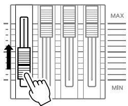
Adjusting the Volume by Using the Sliders 31
Playing Along With the Click 32
Start the Click (Metronome) 32
Changing the Tempo and Time Signature
(Beat) of the Click 33
Tap Tempo 34
Playing Along With a Song 35
SongPlayback 35
Adjusting the Volume of the Song
Accompaniment 38
Changing the Tempo of the Song 38
Song Part Mute Setting 39
Creating a Drum Kit 40
Recording Your Drum Performance to a Song... 43
Recording System. 43
Recording Methods. 43
Recording Your Drum Performance to a Song.....44
Recording Additional Notes to an
Already-recorded Track (Overhub) 46
Recording Along With the Preset Song 46
Re-recording a Track After Clearing 48
Assigning a Name to a User Song. 49
Using the Groove Check Function 50
Setting the Check Timing 50
Trying Out Groove Check. 51
Trying Out Rhythm Gate 52
Saving the Created Data to a USB Storage
Device 54
File/Folder Selection 54
Saving the Created Data to a USB Storage
Device. 55
Loading a File Saved to a USB Storage Device... 56
Reference 57
Basic Structure of the DTX900 57
The Functional Blocks 57
Pads (Trigger Input Sources) and
Trigger Signals 58
Tone Generator Block (Drum Kits and
Drum Voices) 62
Sampling. 65
Song 67
Effects 68
Internal Memory and File Management 76
Drum Kit Mode [DRUM KIT] 78
Basic Procedure in the Drum Kit Mode 78
Selecting a Drum Kit [F1] PLAY 79
Setting Drum Voice Parameters [F2] VOICE......79
Programming the Stack/Alternate [F3] STK/ALT..86
Effect Settings [F4] EFFECT 89
Pad Settings [F5] PAD. 92
Other Settings [F6] OTHER 95
Song Mode [SONG] 98
Song Play [F1] PLAY 98
Song Recording [F1] PLAY [REC] 98
Song Jobs [F2] JOB 98
Click Mode [CLICK] 104
Basic Procedure in the Click Mode. 104
Basic Settings of the Click Sound [F1] PLAY..... 105
Click Voice Settings [F2] VOICE 106
Tap Tempo Function [F3] TAP 106
Groove Check Function [F4] GROOVE 106
Click Sound Settings [F5] OTHER 107
Trigger Mode [TRIGGER] 108
Basic Procedure in the Trigger Mode 108
Selecting the Trigger Setup [F1] SELECT 109
Selecting the Pad Type [F2] TYPE 109
Trigger Sensitivity Settings [F3] SENS 109
Setting the Rejection [F4] REJECT 110
Other Settings [F5] OTHER 111
File Mode [FILE] 112
Terminology in the File Mode 112
File Types Compatible With the DTX900 113
Saving a File [F1] SAVE 114
Loading a File [F2] LOAD 116
Changing the Name of a File or Directory [F3] RENAME 121
Deleting a File or Directory [F4] DELETE 122
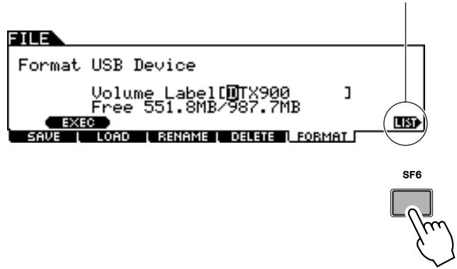
Formatting USB Storage Media [F5] FORMAT .. 123
Utility Mode [UTILITY] 124
Basic Procedure in the Utility Mode. 124
General Settings [F1] GENERAL 124
Pad Settings [F2] PAD. 126
Effect Settings [F3] EFFECT 127
External Audio Settings [F4] AUXIN 128
MIDI Settings [F5] MIDI 130
Resetting the User Memory to the Initial Factory Settings [F6] FACTSET 131
Chain Mode [CHAIN] 132
Using a Programmed Chain [F1] SELECT 132
Programming a Chain [F2] EDIT 133
Naming the Created Chain [F3] NAME 134
Sampling Mode [SAMPLING] 135
Sampling Setup 135
Sampling Operation and User Voice Assignment [F1] SELECT/[F2] SETTING 136
Trimming a User Voice [F3] TRIM 139
Sampling Jobs [F4] JOB 142
Appendix 147
Optional DIMM Installation 147
Troubleshooting 150
Display Messages 153
Specifications. 155
Index 156
About the Accessory Disk. 159
SOFTWARE LICENSE AGREEMENT 159
■ Front Panel
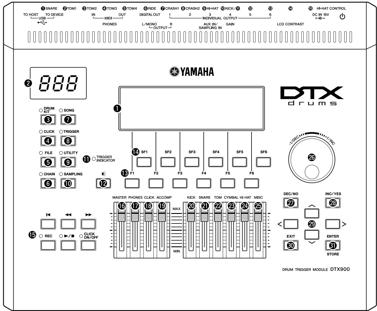
LCD display
The large LCD Display shows information and data needed to operate the DTX900.
NOTE
- Before use, be sure to remove the transparent film applied to the LCD display to protect it during transportation.
LED display
The LED display indicates the current Drum Kit or tempo value in three digits.
NOTE
- Before use, be sure to remove the transparent film applied to the LED display to protect it during transportation.
[DRUM KIT] button
Pressing this button enters the Drum Kit mode, allowing you to select the desired Drum Kit (pages 30 and 78).
4 [CLICK] button
Pressing this button enters the Click mode, allowing you to perform the Click (Metronome) setup (pages 32 and 104).
[FILE] button
Pressing this button enters the File mode, allowing you to manage data created in each of the modes (pages 54 and 112).
6 [CHAIN] button
Pressing this button enters the Chain mode, allowing you to program a Chain, which is a series of Drum Kits and Songs arranged in the order you want (page 132).
[SONG] button
Pressing this button enters the Song mode, allowing you to play an existing Song or record your drum performance (pages 35 and 98).
[TRIGGER] button
Pressing this button enters the Trigger mode, allowing you to select or program a Trigger Setup (pages 22 and 108).
[UTILITY] button
Pressing this button enters the Utility mode, allowing you to set parameters related to the entire system of the DTX900 (page 124).
[SAmplING] button
Pressing this button enters the Sampling mode, allowing you to record the external audio signal then create User Voices (page 135).
1 TRIGGER INDICATOR
This lamp indicates whether or not the DTX900 receives the trigger signal via the Trigger Input jacks. The lamp is turned on when receiving the trigger signal. This lamp is turned on also when pressing the Audition button (described below).
Audition button
You can use this button instead of the drum pad. Pressing this button is equivalent to receiving a signal from the currently selected trigger input source (page 58). When turning the power on, pressing this button is equivalent to striking the head of the snare pad (the pad connected to the SNARE jack).
[15] [F1] - [F6] (Function) buttons
These buttons located directly below the LCD display call up the corresponding functions indicated in the display. In the display hierarchy, these functions [F] rank just below the modes.
[SF1] - [SF6] (Sub-Function) buttons
These buttons located directly below the LCD display call up the corresponding sub functions indicated in the display. In the display hierarchy, these sub functions [SF] rank just below the functions [F].
Transport buttons (page 35)
These buttons control recording and playback of the Song sequence data.
Top) button
Instantly returns to the beginning of the current Song (i.e., the first beat of the first measure).
(Reverse) button
Press briefly to move back one measure at a time, or hold to continuously rewind.
Forward) button
Press briefly to move forward one measure at a time, or hold to continuously fast-forward.
REC (Record) button
Press this to enable Song recording. (The indicator lights.)
▶(Play/Stop) button
Press to start/stop recording or playback. Pressing this button during playback stops playback at the current point in the Song then pressing this again starts playback from that point. During recording and playback, the indicator lights.
CLICK ON/OFF button
Press this button to start/stop the metronome (click sound).
16 MASTER slider (page 31)
Adjusts the output volume of the stereo mix from the OUTPUT L/MONO and R jacks.
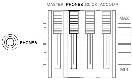
PHONES slider (page 31)
Adjusts the output volume of the stereo-mixed sounds for the PHONES jack. This is independent from the MASTER slider setting.
18 CLICK slider (page 31)
Adjusts the output volume of the click sound.
19 ACCOMP slider (page 31)
Adjusts the output volume of the accompaniment parts (those other than MIDI channel 10) in the Song.
20 KICK slider (page 31)
Adjusts the volume of the bass drum.
SNARE slider (page 31)
Adjusts the volume of the snare drum.
2 TOM slider (page 31)
Adjusts the volume of the toms.
25 CYMBAL slider (page 31)
Adjusts the volume of the cymbals.
HI-HAT slider (page 31)
Adjusts the volume of the hi-hat cymbals.
MISC slider (page 31)
Adjusts the volume of miscellaneous rhythm or percussion sounds – other than snare and bass drums, toms, hi-hats, and ride and crash cymbals.
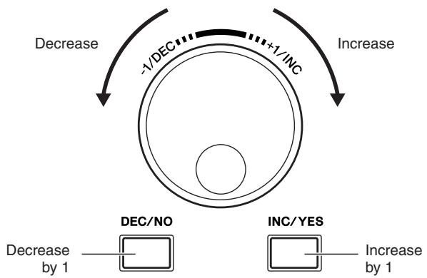
26 Data dial
For editing the currently selected parameter. To increase the value, turn the dial right (clockwise); to decrease the value, turn the dial left (counter-clockwise). If a parameter with a wide value range is selected, you can change the value in broader strokes by quickly turning the dial.
[DEC/NO] button (page 13)
For decreasing the value of the currently selected parameter. Also use it to cancel a Job or a Store operation.
[INC/YES] button (page 13)
For increasing the value of the currently selected parameter. Also use it to actually execute a Job or a Store operation.
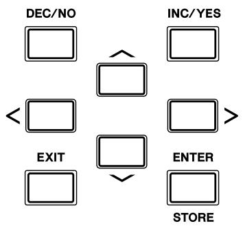
29 Cursor buttons (page 13)
The cursor buttons move the "cursor" around the LCD display screen, highlighting and selecting the various parameters.
[EXIT] button
Press this button to cancel an operation when a confirmation message is shown in the LCD. This button can be used also when the drum sound continues inadvertently or unexpectedly and you want to stop it.
[ENTER/STORE] button
As with the ENTER button, press this to enter the display of the selected Song Job/Sampling Job, for example.
As with the STORE button, press this to store the edited data in the Drum Kit mode, Click mode, Trigger mode, Utility mode, and Chain mode.
You can also use this button when executing the Song Job or Sampling Job.
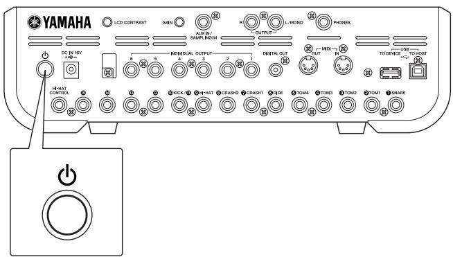
Rear Panel
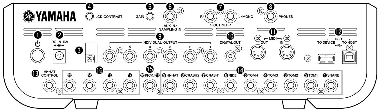
(Standby/On) switch
Press to turn the power ON or OFF.
DC IN terminal
Connect the AC power adaptor to this terminal.
3 Cable clip
Wrap the DC output cable of the adaptor around the cable clip to prevent accidental unplugging of the cable during operation.
4 LCD Contrast Control
Use this control to set the LCD display for optimum legibility.
GAIN knob
For adjusting the input gain of the audio at the AUX IN/SAMPLING IN jack. Depending on the connected device (microphone, CD player, etc.), you may need to adjust this for optimum level. Increase the gain by rotating the knob clockwise, and decrease it by rotating the knob counter-clockwise.
6 AUX IN/SAMPLING IN jack
External audio signals can be input via this phone jack (standard stereo phone plug). This is convenient for playing along with music from a CD player or other device. In the Sampling mode, this jack is used for capturing audio data as User Voices.
OUTPUT L/MONO and R jacks
External audio signals can be input via these phone jacks (1/4" mono phone plug). Various devices such as microphone, guitar, bass, CD player, can be connected to these jacks. For stereo signals (such as from audio equipment), use both jacks. For mono signals (such as from a microphone or guitar), use only the L jack.
⑧ PHONES jack
For connection to a pair of stereo headphones.
INDIVIDUAL OUTPUT 1-6 jacks
Line level audio signals are output from this instrument via these phone jacks (1/4" mono phone plug). These outputs are independent of the main output (at the L/MONO and R jacks), and can be freely assigned to any Drum Voice. This lets you route specific sounds for processing with a favorite outboard effect unit.
DIGITAL OUT connector
This is for connecting to a coaxial digital input (S/P DIF) on an external audio device. This jack digitally outputs stereo audio signals identical to those from the OUTPUT L/MONO and R jacks, but is not affected by the 16 MASTER volume slider setting (the digital jack always outputs audio signals at the maximum volume level).
1 MIDI IN/OUT connectors
These jacks are for the transfer of MIDI data to and from external MIDI devices.
USB terminals
This instrument is equipped with two types of USB terminals on the rear panel - USB TO HOST and USB TO DEVICE. The USB TO HOST terminal is used to connect this instrument to the computer via the USB cable. The USB connection between the instrument and the computer can only be used for transfer of MIDI data. No audio data can be transferred via USB. The USB TO DEVICE terminal is used to connect this instrument to a USB storage device (flash memory, hard disk drive, etc.) via the USB cable. This lets you save the data created on this instrument to an external USB storage device as well as load data from the device to the instrument. Save/Load operations can be performed in the File mode.
HI-HAT CONTROL jack
This jack is used to connect a hi-hat controller. Depending on the setting on the Drum Kit mode (page 78), you can transmit the MIDI messages such as Control Change by using the Hi-Hat Controller.
Trigger Input Jacks (SNARE - HI-HAT)
These jacks, which are compatible with stereo pads (two-zone and three-zone pads) as well as mono pads, receive the Trigger Signal transmitted from the drum pads. Furthermore, the ① SNARE - ⑤ TOM4 jacks are also compatible with the Pad Controller (page 59).
15 Trigger Input jack (10/11 KICK)
This jack is designed to accept two separate trigger signals from two mono (single) pad by using a Y-shaped cable (stereo phone plug for this jack and two mono plugs for the two pads). When using the KP125W/KP65 equipped with the PAD INPUT jack, the Trigger Signals of another pad connected to the PAD INPUT jack and KP itself can be transferred via a single stereo cable (no need for a Y-shaped cable) to the DTX900. In this case, the stereo cable is plugged into the OUTPUT jack of a pad and this Trigger Input jack.
16 Trigger Input jacks (12 - 15)
These jacks, which are compatible with stereo pads (two-zone and three-zone pads) as well as mono pads, receive the Trigger Signal transmitted from the drum pads.
Moving the Cursor
Use these four buttons to navigate through the display, moving the cursor around the various selectable items and parameters in the screen. When selected, the relevant item is highlighted (the cursor appears as a dark block with inverse characters). You can change the value of the item (parameter) at which the cursor is located by using the data dial, [INC/YES] and [DEC/NO] buttons.
Changing or Editing Parameter Values
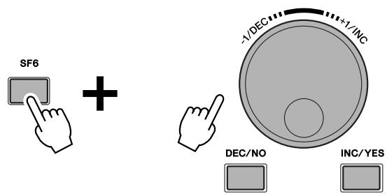
Rotating the data dial to the right (clockwise) increases the value, while rotating it to the left (counter-clockwise) decreases it. For parameters with large value ranges, you can increase the value by 10 by simultaneously holding down the [INC/YES] button and pressing the [DEC/NO] button. To decrease by 10, do the opposite; simultaneously hold down the [DEC/NO] button and press the [INC/YES] button.
Functions and Sub-Functions
Each mode described above contains various displays, with various functions and parameters. To navigate your way through these displays and select a desired function, use the [F1] - [F6] buttons and the [SF1] - [SF6] buttons. When you select a mode, the available displays or menus appear directly above the buttons at the bottom of the display (as shown below).
Depending on the currently selected mode, up to six functions are available and can be called up with the [F1] - [F6] buttons. Keep in mind that the available functions differ depending on the selected mode.
Depending on the currently selected mode, up to six functions (sub-functions) are also available and can be called up with the [SF1] – [SF6] buttons. Keep in mind that the available functions differ depending on the selected mode.
(Some displays may not have any sub-functions for these buttons.)
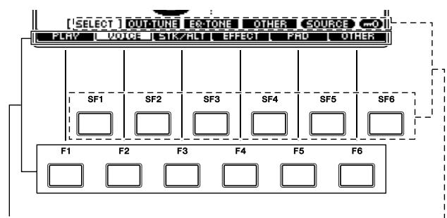
These functions can be selected via the corresponding button ([F1] - [F6]).
These functions can be selected via the corresponding button ([SF1] - [SF6]).
Modes
In order to make operation of the DTX900 as comprehensive and as smooth as possible, all functions and operations have been grouped in "modes." To enter the desired mode, press the corresponding Mode button.
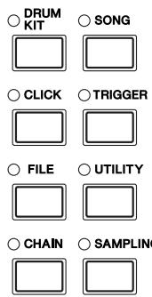
The function of each mode is as follows:
| Mode | Function | Page |
| Drum Kit | Selecting/editing a Drum Kit. | 78 |
| Click | Setting the Click (Metronome) related parameters and performing the Groove Check function. | 104 |
| File | Managing files and directories (Folders). | 112 |
| Chain | Programming a Chain sequence. | 132 |
| Song | Selecting/recording a Song. | 98 |
| Trigger | Selecting/editing a Trigger Setup. | 108 |
| Utility | Setting the system related parameters. | 124 |
| Sampling | Recording audio signals to create a User Voice. | 135 |
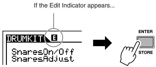
Edit Indicator
You can adjust or set various parameters by using the data dial, [INC/YES] button and [DEC/NO] button in each mode. When changing the value of the parameter in these modes, the [E] (Edit Indicator) will appear on the top left corner of the LCD display. This indicates that the current program (Drum Kit, etc.) has been modified but not yet stored. If you wish to store the status or sound obtained by editing, be sure to store the current program to internal User memory by pressing the [ENTER/STORE] button before selecting another program.
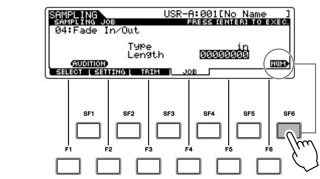
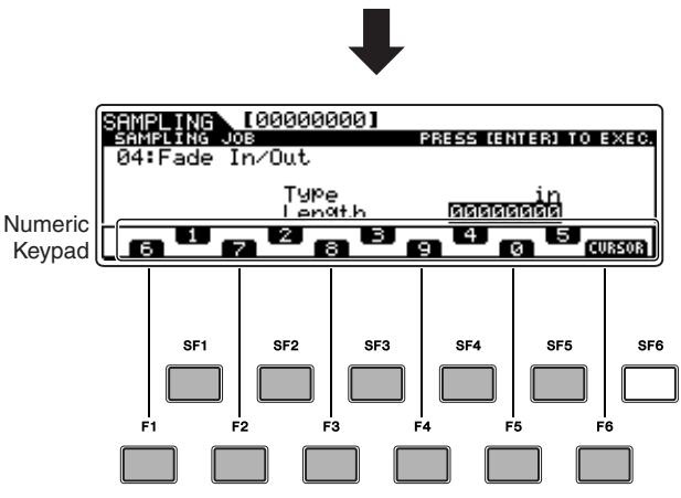
Inputting a Number Directly
For parameters having large value ranges, you can also enter the value directly, using the buttons below the LCD display as a numeric keypad. When the cursor is located on such a parameter, the [NUM] icon appears at the lower right corner of the LCD display. When the [SF6] NUM button is pressed in this status, each digit (1 - 9,0) is assigned to the [SF1] – [SF5] and [F1] – [F5] buttons as shown below, allowing you to input a number directly by using these buttons.
After completing the number input, press the [ENTER/STORE] button to actually enter the number.
Note that the cursor highlight can be moved to the currently edited number by pressing the [F6] CURSOR button, and then moved from digit to digit by using the Cursor [<] and [>] buttons. This method is useful when you want to directly change only one specific digit. The cursor disappears when pressing the [F6] button again.
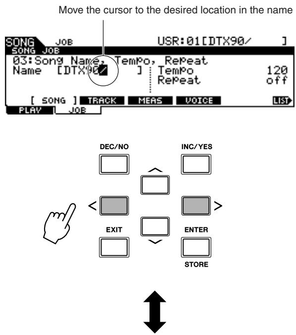
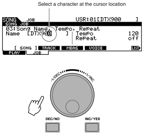
Inputting Characters (Naming, etc.)
As shown below, you can set the name by repeating the two operations - moving the cursor to the desired location by using the Cursor buttons and then selecting a character by using the data dial, [INC/YES] button, and [DEC/NO] button.
Using the character list
If you find it difficult to select the desired characters with the above method, you may want to use the following method - selecting the characters directly from a list.
When the cursor is located at the Name, this [LIST] icon appears and you can call up the Character List display by holding the [SF6] button. Release the [SF6] button to return back to the original display.
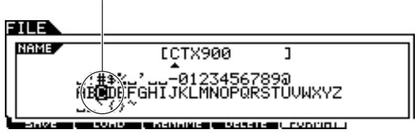
Perform the operations below while holding the [SF6] button.
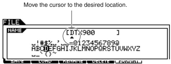
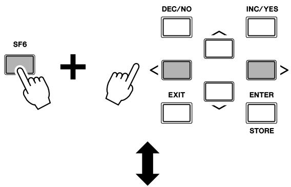
Select a character for the cursor location in the name.
IMPORTANT
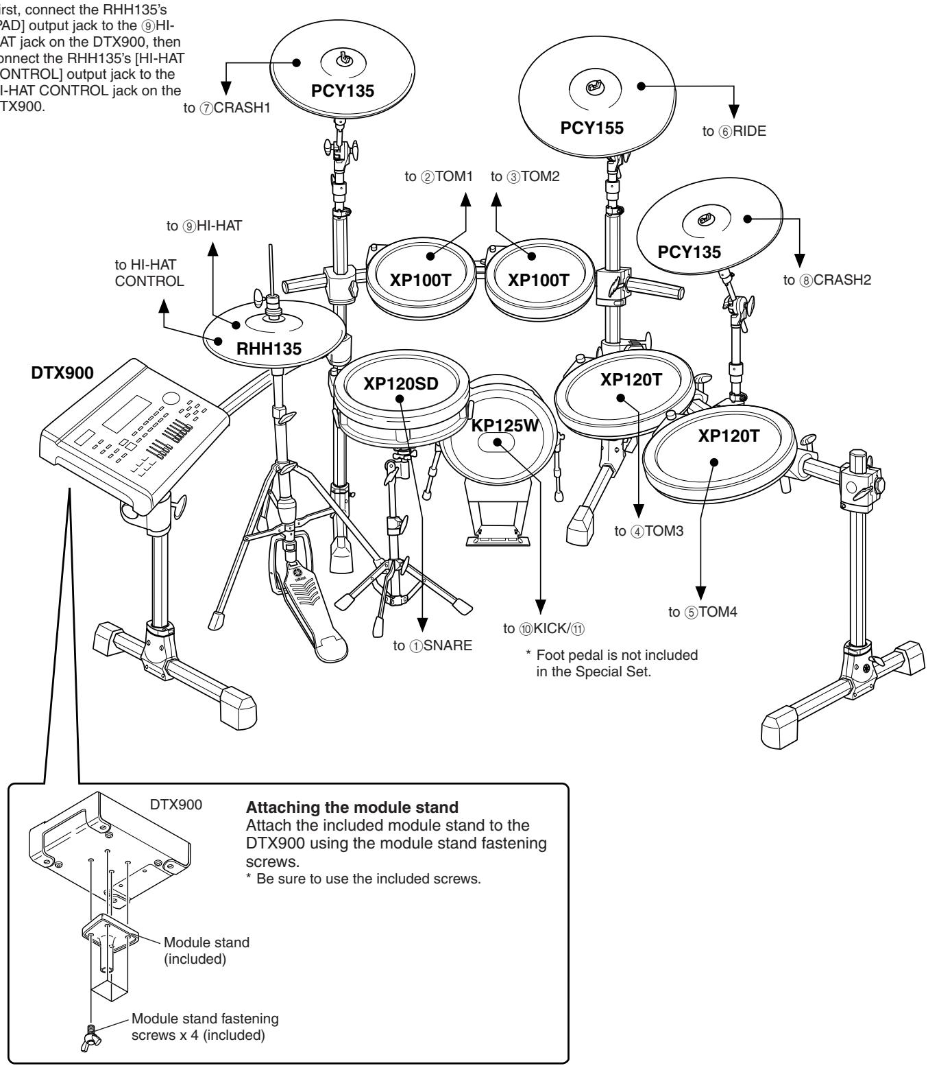
You'll need to change the Trigger Settings of the DTX900 according to the type of drum set you are using (Standard Set/Special Set/Acoustic Drums, etc.). If the setting is not appropriate, problems may occur—such as improper sound, or inappropriate volume balance among the pads. Refer to the "Selecting the Trigger Setup" section on page 22 on how to select the appropriate setup.
Connecting the Pads
Referring to the illustration below, connect the output cable from each pad to each Trigger Input jack located on the rear panel of the DTX900. All Trigger Input jacks are conveniently labeled (① SNARE, etc.), so make sure each pad is connected to its corresponding Trigger Input jack.

WARNING
- To prevent electric shock and damage to the devices, make sure the power is switched OFF on the DTX900 and all related devices before making any connections to the DTX900's input and output jacks.
DTX900K
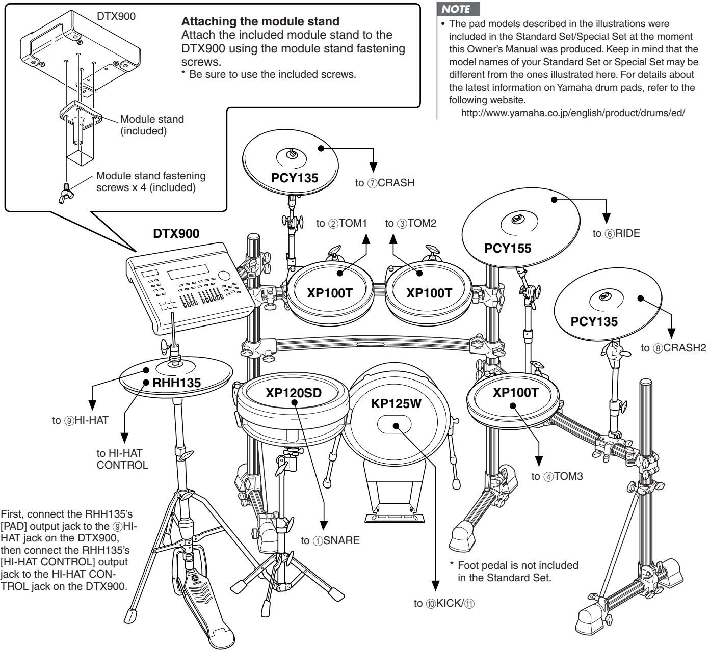
- First, connect the RHH135's [PAD] output jack to the ⑨HI-HAT jack on the DTX900, then connect the RHH135's [HI-HAT CONTROL] output jack to the HI-HAT CONTROL jack on the DTX900.
DTX950K
- First, connect the RHH135's [PAD] output jack to the ⑨HI-HAT jack on the DTX900, then connect the RHH135's [HI-HAT CONTROL] output jack to the HI-HAT CONTROL jack on the DTX900.
Setting up with Acoustic Drums
The DTX900 can be played from an acoustic drum kit if the kit is fitted with an optional set of drum triggers (such as Yamaha DT20 Drum Triggers) and the triggers are properly connected to the input jacks of the DTX900.
Setting Up the Power Supply
1 Make sure that the (Standby/On) switch of the instrument is set to standby ( ).
2 Connect the DC plug of the included AC power adaptor to the DC IN jack on the rear panel. To prevent the cord from being unplugged accidentally, wrap the cord around the cable clip and secure it.
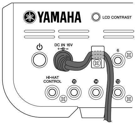

CAUTION
- Make sure that the power adaptor's cord is not bent at an extreme angle when wrapping the cord around the clip. Doing this can damage or sever the cord and create a fire hazard.
3 Connect the other end of the power cord to an AC outlet.

WARNING
- Use only the included power adaptor or an equivalent recommended by Yamaha. The use of any other adaptors may cause irregular operation or damage to the device.
- Only use the voltage specified as correct for the DTX900.
- Even when the instrument is turned off, electricity is still flowing to the instrument at the minimum level. When you are not using the DTX900 for a long time, make sure to unplug the AC power adaptor from the wall AC outlet.
Turning the Power On
After you've made all necessary connections (trigger, audio, MIDI), turn down all volume controls of the DTX900 and other audio equipment.
Turn the power on ( ) by pressing the (Standby/On) switch on the rear panel of the DTX900, then turn on the power of the amplifiers.
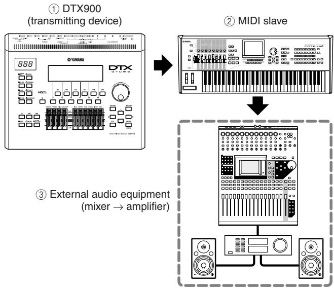
- Connecting a mixer or other MIDI devices
Make sure that all volume settings are turned down all the way to the minimum. Then turn on the every device in your setup in the order of MIDI masters (controllers), MIDI slaves (receivers), then audio equipment (mixers, amplifiers, speakers, etc.).
NOTE
- When powering down the setup, first turn down the volume for each audio devices, then switch off each device in the reverse order (first audio equipment, then MIDI).
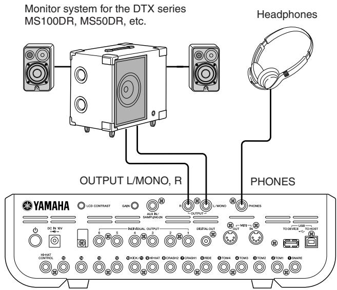
Connecting to Speakers or Headphones
Since the DTX900 has no built-in speakers, you'll need an external audio system or a set of stereo headphones to properly monitor it.
NOTICE
- Whenever making connections, make sure that the plug on the cable being used corresponds to the type of jack on the device.
OUTPUT L/MONO, R jacks (standard mono phone)
These jacks allow you to connect the DTX900 to an external amplifier/speaker system and produce full, amplified sound.
- Use the DTX900's OUTPUT L/MONO jack when connecting to a device with a mono input.
PHONES jack (standard stereo phone jack)
The overall headphone level is adjusted by the PHONES slider.

CAUTION
- Do not use the DTX900 at a high volume level for a long period of time, or your hearing may be damaged. Doing so may cause hearing loss.
Connecting to External Audio Equipment
When recording your performance on a DTX900 Drum Kit or sending its sounds to a mixer, connect your equipment as follows:
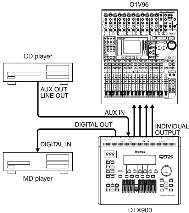
The OUTPUT (L/MONO and R) and INDIVIDUAL OUTPUT (1 to 6) jacks produce line level audio signals regardless of whether headphones are connected or not. These jacks are mono phone type. To make audio connections via these jacks, use cables with a mono phone plug for the DTX900 and an appropriate plug for the other device.
Use both OUTPUT jacks (L/MONO and R) for stereo output. If the other device has a mono input, use the L/MONO jack only.
NOTE
- Connect a set of headphones to the PHONES jack for monitoring the stereo output (identical to that of the OUTPUT jacks). The sounds output from the INDIVIDUAL OUTPUT jacks cannot be heard from the headphones connected to the PHONES jack.
- Depending on the connected equipment, you may need to change the parameter settings in the Utility mode. For details, see page 128.
The DIGITAL OUTPUT connector can be connected to a coaxial digital input (S/P DIF) on an external audio device. This connector digitally outputs stereo audio signals identical to those from the OUTPUT L/MONO and R jacks.
External audio signals input to AUX IN/SAMPLING IN jack can be monitored together with the DTX900 sounds via headphones connected to the PHONES jack, and can be recorded to create additional User Voices. If necessary, you can use the [GAIN] knob on the rear panel to adjust the gain of the input signal.
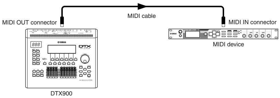
Connecting External MIDI Devices
Using a standard MIDI cable (available separately), you can connect an external MIDI device, and control it from the DTX900.
This connection lets you sound an external MIDI tone generator (synthesizer, tone generator module, etc.) by playing the DTX900 or playing back a Song on the DTX900. Also, an external sequencer can be used to drive the DTX900's Tone Generator. Furthermore, the use of MIDI functions allows for an even greater range of performance and recording possibilities with the DTX900.
NOTE
- Any one of the DTX900 interfaces (MIDI connectors or the USB terminal) can be used for MIDI data transmission/ reception. However, they cannot be used at the same time. Select which connector is used for MIDI data transfer in the Utility mode with the following operation: [UTILITY] [F5] MIDI [SF3] OTHER MIDI IN/OUT
Controlling an external tone generator or synthesizer
Use a MIDI cable to connect the MIDI OUT connector on the DTX900 with the MIDI IN connector on the external MIDI device.
■ Controlling from an external MIDI keyboard or synthesizer
Use a MIDI cable to connect the MIDI IN connector on the DTX900 with the MIDI OUT connector on the external MIDI device.
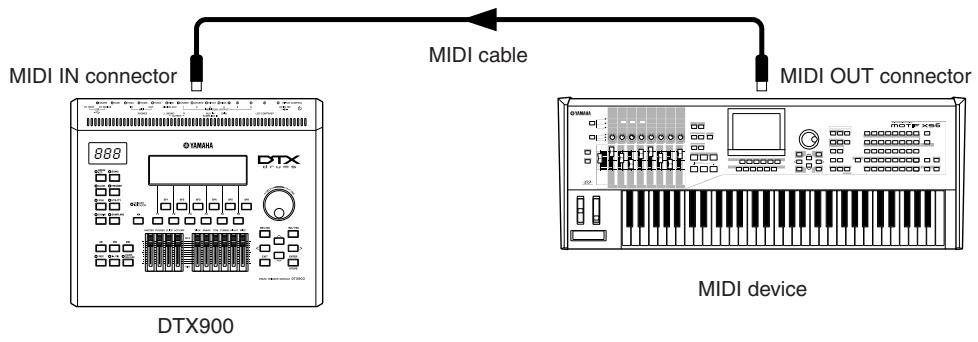
Synchronizing with an external MIDI instrument (Master and Slave)
The Songs of this instrument can be synchronized to the playback of an external MIDI sequencer, To do this, one device must be set to internal clock operation and the other (as well as all other devices to be controlled) to external clock. The device set to internal clock serves as a reference for all connected devices, and is referred to as the "master" instrument. The connected devices set to external clock are referred to as "slaves." When recording playback data of an external MIDI sequencer to a Song of the DTX900 in the above connection example, make sure to set the MIDI synchronization parameter to follow external clock with the following operation in the Utility mode.
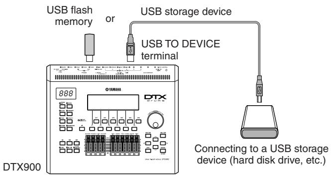
Connecting a USB Storage Device
You can connect a USB storage device to the USB TO DEVICE terminal on the rear panel of this instrument.
Precautions When Using the USB TO DEVICE Terminal
This instrument features a built-in USB TO DEVICE terminal. When connecting a USB device to the terminal, be sure to handle the USB device with care. Follow the important precautions below.
NOTE
- For more information about the handling of USB devices, refer to the owner's manual of the USB device.
Compatible USB devices
USB storage devices (flash memory, hard disk drive, etc.)
The instrument does not necessarily support all commercially available USB devices. Yamaha cannot guarantee operation of USB devices that you purchase. Before purchasing a USB device for use with this instrument, please consult your Yamaha dealer, or an authorized Yamaha distributor (see list at end of the Owner's Manual) for advice, or visit the following web page:
http://www.yamaha.co.jp/english/product/drums/ed/
NOTE
- Other USB devices such as a computer keyboard or mouse cannot be used.
Connecting a USB device
When connecting a USB device to the [USB TO DEVICE] terminal, make sure that the connector on the device is appropriate and that it is connected in the proper direction.
Though the instrument supports the USB 1.1 standard, you can connect and use a USB 2.0 storage device with the instrument. However, note that the transfer speed is that of USB 1.1.
Using USB Storage Devices
By connecting the instrument to a USB storage device, you can save data you've created to the connected device, as well as read data from the connected device.
NOTE
- Although CD-R/RW drives can be used to read data to the instrument, they cannot be used for saving data.
■ Formatting USB storage media
When a USB storage device is connected or media is inserted, a message may appear prompting you to format the device/media. If so, execute the Format operation (page 123).
NOTICE
- The format operation overwrites any previously existing data. Make sure that the media you are formatting does not contain important data.
To protect your data (write-protect)
To prevent important data from being inadvertently erased, apply the write-protect provided with each storage device or media. If you are saving data to the USB storage device, make sure to disable write-protect.
- Connecting/removing a USB storage device
Before removing the media from the device, make sure that the instrument is not accessing data (such as in the Save, Load and Delete operations).
NOTICE
- Avoid frequently turning the power on/off to the USB storage device, or connecting/disconnecting the device too often. Doing so may result in the operation of the instrument "freezing" or hanging up. While the instrument is accessing data (such as during Save, Delete, Load and Format operations), do NOT unplug the USB connector, do NOT remove the media from the device, and do NOT turn the power off to either device. Doing so may corrupt the data on either or both devices.
Selecting the Trigger Setup
The Trigger Setup contains various settings related to Trigger Input Signals received from pads or drum triggers (Yamaha DT20, etc.) that are connected to the Trigger Input jacks. These settings let you optimize the DTX900 for best operation and response to these signals.
Select an appropriate Trigger Setup for your Drum Kit from the pre-programmed Trigger Settings in the DTX900. Use the operation described below to select the Trigger Setup you want to use.
Selecting the Trigger Setup
Press the [TRIGGER] button to enter the Trigger mode.
The Trigger selection display appears.
![YAMAHA DTX-900 - Press the [TRIGGER] button to enter the Trigger mode. - 1](/content/2025/01/114986/images/c9a137f448caa5b9e167e53d4746dee70ae9b68099fbba371955c9aef8afa00c.jpg)
① Trigger Setup number
Indicates the current Trigger Setup number.
Settings PRE:01-PRE:09,USR:01-USR:05
② Trigger Input Level Indicator
As soon as you strike the pad, the Trigger Input Level is shown as a bar graph above the number corresponding to the Trigger Input jack connected to the pad you've hit.
③ [SF6] Input Lock
Pressing this button turns the Input Lock ("L" indicator at the right corner of the display) on or off. Normally, the Trigger Input jack or Trigger Input Source to be edited can be determined by hitting the corresponding pad. If you want to maintain it even if you hit one of the pads, press this button to turn the Input Lock ("L" indicator) on.
2 Select the desired Trigger Setup number by using the data dial, [INC/YES] button or [DEC/NO] button.
For information about each Trigger Setup, refer to the Trigger Setup List on page 23.
Setting a Default Trigger Setup to be Called Up When the Power is Turned On
If you want a particular Trigger Setup (i.e., the one you've selected above) to be called up every time the power of the DTX900 is turned on, follow the instructions below.
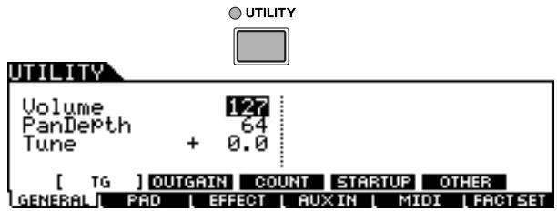
Press the [UTILITY] button to enter the Utility mode.
2 Press the [F1] GENERAL button followed by the [SF4] START UP button to call up the Start Up display.
![YAMAHA DTX-900 - Press the [F1] GENERAL button followed by the [SF4] START UP button to call up the Start Up display. - 1](/content/2025/01/114986/images/645181e4dc36e23be556e199a503afb70b11255d56a72e923c28ae98bcda4d94.jpg)
① TriggerNo (Trigger Setup number)
Indicates the Trigger Setup number called up when the power of the DTX900 is turned on.
3 Move the cursor to the Trigger Setup number, then select the desired number by using the data dial, [INC/YES] button or [DEC/NO] button.
For information about each Trigger Setup, refer to the Trigger Setup List on page 23.
4 Press the [ENTER/STORE] button to store the setting.
NOTE
- You can create your original Trigger Setup by editing various parameters. For details, see page 108.
NOTICE
- For Factory Set operations that take longer to process, a message "Please keep power on..." appears during processing. While such a message is shown (while data is being written to Flash ROM), never attempt to turn off the power. Turning the power off in this state results in loss of all user data and may cause the system to freeze (due to corruption of data in the Flash ROM). This may cause the instrument to not start up properly, even when turning the power on next time.
Trigger Setup List
| No. | Name | Description | |
| PRE: 01 | XP Wide | For DTX950K/900K | Wide dynamic range. This setting is designed for maximum expressive control, allowing performance subtleties over a wide dynamic range. |
| PRE: 02 | XP Normal | Normal setting | |
| PRE: 03 | SP Wide | For DXTREME III Special Drum Set | Wide dynamic range. This setting is designed for maximum expressive control, allowing performance subtleties over a wide dynamic range. |
| PRE: 04 | SP Normal | Normal setting | |
| PRE: 05 | SP Narrow | Controlled dynamic range delivers stable trigger detection. This setting is designed for producing a smoother, more uniform sound with reduced volume fluctuations. | |
| PRE: 06 | STD Wide | For DXTREME III Standard Drum Set | Wide dynamic range. This setting is designed for maximum expressive control, allowing performance subtleties over a wide dynamic range. |
| PRE: 07 | STD Normal | Normal setting | |
| PRE: 08 | STD Narrow | Controlled dynamic range delivers stable trigger detection. This setting is designed for producing a smoother, more uniform sound with reduced volume fluctuations. | |
| PRE: 09 | DT10/20 | — | Use for DT10/20 drum trigger systems applied to acoustic drums. |
| USR: 01 – 05 | User Trigger | — | Allows creation of custom trigger setups. |
- In the default setting, "PRE: 01 XP Wide" for DTX950K/900K is selected.
Resetting the User Memory to the Initial Factory Settings
The original factory settings of this instrument's User Memory (page 76) can be restored as follows. For each of all modes, you can set whether or not User Memory data is initialized.
NOTICE
- When the factory settings are restored, all the data you created in each mode will be erased. Make sure you are not overwriting any important data. Be sure to save all important data to a USB storage device before executing this procedure (page 114).
Press the [UTILITY] button to enter the Utility mode.
2 Press the [F6] FACTSET button to call up the Factory Set display.
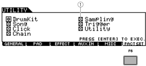
① checkbox
If you enter a checkmark for a mode name in the display (in step 3 below), executing the Factory Set will reset the User Memory data or settings of the corresponding mode to the initial factory settings. For those modes without checkmarks, the User Memory data or settings will be maintained even if Factory Set is executed.
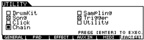
3 Move the cursor to the checkbox of the desired mode then enter or remove the checkmark by using the data dial, [INC/ YES] button or [DEC/NO] button.
4 Press the [ENTER/STORE] button.
The display prompts you for confirmation. Press the [DEC/NO] button or [EXIT] button to cancel the operation.
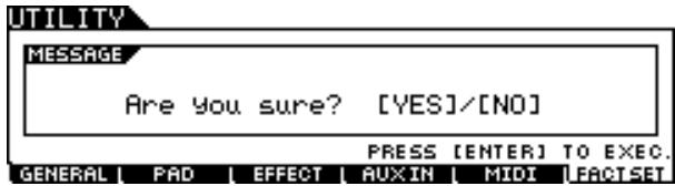
Press the [INC/YES] button to execute the Factory Set operation.
After the Factory Set has been completed, a "Completed" message appears and operation returns to the original display.
NOTICE
- For Factory Set operations that take longer to process, a message "Executing..." or "Please keep power on." appears during processing. While such a message is shown (while data is being written to Flash ROM), never attempt to turn off the power. Turning the power off in this state results in loss of all user data and may cause the system to freeze (due to corruption of data in the Flash ROM). This means that this instrument may not be able to start up properly, even when turning the power on next time.
Connecting a Computer
Although the DTX900 is exceptionally powerful and versatile all by itself, connecting it to a computer – via USB cable – provides even greater power and versatility. This feature lets you transfer MIDI data between the DTX900 and your computer. In this section you'll learn how to make the connections.
NOTE
- Since the DTX900 has no built-in speakers, you'll need an external audio system or a set of stereo headphones to properly monitor it. For details, see page 19.
Download the USB-MIDI driver from our website:
http://www.global.yamaha.com/download/usbmidi/
NOTE
- Information on system requirements is also available at the above web site.
NOTE
- The USB-MIDI driver may be revised and updated without prior notice. Make sure to check and download the latest version from the above site.
2 Install the downloaded USB-MIDI driver to the computer.
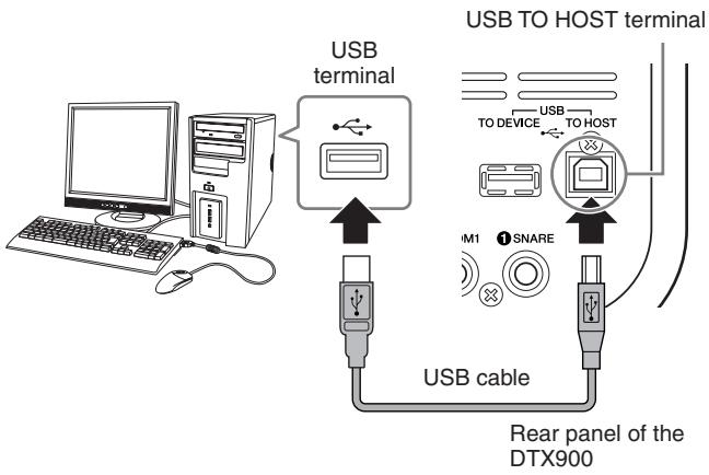
For instructions on installing, refer to the online Installation Guide included in the downloaded file package. When connecting the DTX900 to a computer in the Installation procedure, connect the USB cable to the USB TO HOST of the DTX900 and the USB terminal of the computer as shown below.
3 Make sure that the USB TO HOST terminal of the DTX900 is enabled.
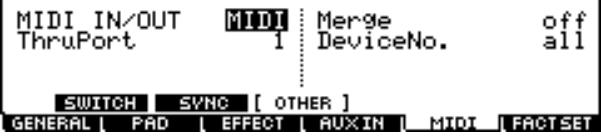
Press the [UTILITY] button to enter the Utility mode, then press the [F5] MIDI button followed by the [SF3] OTHER button.
UTI TY
4 Set the MIDI IN/OUT parameter to "USB" by using the [DEC/NO] button, [INC/YES] button or data dial.
![YAMAHA DTX-900 - Set the MIDI IN/OUT parameter to "USB" by using the [DEC/NO] button, [INC/YES] button or data dial. - 1](/content/2025/01/114986/images/6c804d2e22663d4c57717ca5518e215faadbef9fa1b99c645ac235a0fa5dec70.jpg)
UTI TY
Press the [ENTER/STORE] button to store this setting.
Precautions when using the USBTO HOST terminal
When connecting the computer to the USB TO HOST terminal, make sure to observe the following points. Failing to do so risks freezing the computer and corrupting or losing the data. If the computer or the instrument freezes, restart the application software or the computer OS, or turn the power to the instrument off then on again.
NOTICE
- Use an AB type USB cable of less than about 3 meters.
- Before connecting the computer to the USB TO HOST terminal, exit from any power-saving mode of the computer (such as suspended, sleep, standby).
- Before turning on the power to the instrument, connect the computer to the USB TO HOST terminal.
- Execute the following before turning the power to the instrument on/off or plugging/unplugging the USB cable to/from the USB TO HOST terminal.
- Quit any open application software on the computer.
- Make sure that data is not being transmitted from the instrument. (Data is transmitted only by playing pads or playing back a Song.)
- While a USB device is connected to the instrument, you should wait for six seconds or more between these operations: (1) when turning the power of the instrument off then on again, or (2) when alternately connecting/disconnecting the USB cable.
Setting up Cubase Remote Control
Using this special feature, the DTX900 can operate as a remote controller for Cubase. For example, you can operate the Cubase transport, turn its metronome on or off, and control various other functions from the instrument's front panel, significantly increasing the efficiency of your music production workflow.
Computer settings
When setting up Cubase remote control for the first time, complete the following steps to properly configure your computer.
Download the latest version of the DTX900 Extension from the following web page.
Save the compressed file in a convenient location and then expand it.
http://www.yamaha.co.jp/english/product/drums/ed
NOTE
- Ensure that the latest USB MIDI driver is installed on your computer (see page 24).
- Information on system requirements is also provided on the above web page.
- The DTX900 Extension may be revised and updated without prior notice. Before installing, visit the above web page to confirm the latest related information and ensure that you have the most up-to-date version.
2 Execute the expanded DTX900 Extension to carry out the required installation procedure. For more details, refer to the owner's manual included in the downloaded package.
DTX900 settings
In order to use the Cubase Remote function, the following steps must be performed on the DTX900.
1 Make sure that the USB TO HOST terminal of the DTX900 is enabled.
Press the [UTILITY] button to enter the Utility mode, then press the [F5] MIDI button followed by the [SF3] OTHER button. For details, see page 131.
2 Set the MIDI IN/OUT parameter to "USB" by using the [DEC/NO] button, [INC/YES] button or data dial.
3 Ensure that the DTX900 is connected to your computer in the correct manner, and then launch Cubase.
For more details regarding connection, see page 24.
4 Simultaneously hold down the [CHAIN] button and press the [SAMPLING] button.
The message "Cubase Remote" will be displayed to confirm that the function has been activated.
REMOTE
CUBASE REMOTE
Press [CHAIN]+[SAMPLING] to exit.
5 To deactivate Cubase Remote mode, again simultaneously hold down the [CHAIN] button and press the [SAMPLING] button.
■ Button Functions in Cubase Remote Mode
| Button | Operation |
| [◁] | Returns the transport to the start of the song (TOP). |
| [◁] | Rewinds the transport (REW). |
| [▷] | Fast forwards the transport (FF). |
| [REC] | Starts recording. |
| [▷/■] | Starts and stops playback. |
| [CLICK ON/OFF] | Turns the click track on and off. |
| [▷] | Turns Solo Defeat of the currently selected track on and off. |
| [F1] | Quantize* |
| [F2] | Undo* |
| [F3] | Zoom In* |
| [F4] | Zoom Out* |
| [F5] | Zoom in the selected track* |
| [F6] | Zoom out the selected track* |
| [SF1] | Not assigned * |
| [SF2] | Not assigned * |
| [SF3] | Not assigned * |
| [SF4] | Not assigned * |
| [SF5] | Not assigned * |
| [SF6] | Not assigned * |
| [-1/DEC], [+1/INC] | Moves the project cursor by 1 bar. |
| [INC/YES] | Decreases the program number of the currently selected VST instrument by 1. |
| [DEC/NO] | Increases the program number of the currently selected VST instrument by 1. |
| [←] | Selects the previous track. |
| [→] | Selects the next track. |
| [<] | Selects the previous track. |
| [>] | Selects the next track. |
| [CHAIN]+[SAMPLING] | Turns the Cubase Remote function on and off. |
- You can assign any Cubase function to the button.
Creating a Song by Using a Computer
Recording Your Performance on the DTX900 to Computer
NOTE
- The acronym DAW (digital audio workstation) refers to music software for recording, editing and mixing audio and MIDI data, such as Cubase.
Setting up the DTX900
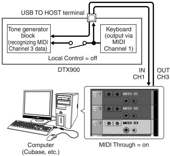
On the DTX900, you need to set the Local Control parameter to "off" in order to avoid a "double" sound.
When MIDI Thru is set to "on" in a DAW/sequencer software on your computer, the note events you play on the DTX900 are transmitted to the computer then returned back to the DTX900, producing a "double" sound, since the tone generator block is receiving performance data (MIDI data) from both the keyboard directly and the computer. To prevent such a situation, you need to separate the keyboard block from the tone generator block of the
DTX900. This is why Local Control should be set to "off."
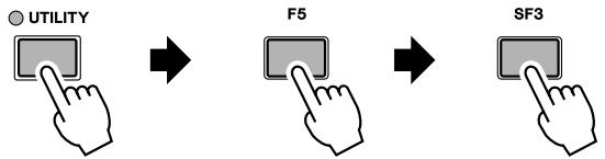
Press the [UTILITY] button to enter the Utility mode, then press the [F5] MIDI button followed by the [SF1] SWITCH button.
![YAMAHA DTX-900 - Press the [UTILITY] button to enter the Utility mode, then press the [F5] MIDI button followed by the [SF1] SWITCH button. - 1](/content/2025/01/114986/images/050554f6ecb0a2b0f5a9a77c2b574de9c387b2d8976dae7f2a36d1308ad042db.jpg)
UTILITY
![YAMAHA DTX-900 - Press the [UTILITY] button to enter the Utility mode, then press the [F5] MIDI button followed by the [SF1] SWITCH button. - 2](/content/2025/01/114986/images/95c2a3bf2a98a41cf55a5f3a573b3166c2f1bf2bee59a8047879f4e4ee1b479a.jpg)
![YAMAHA DTX-900 - Press the [UTILITY] button to enter the Utility mode, then press the [F5] MIDI button followed by the [SF1] SWITCH button. - 3](/content/2025/01/114986/images/0a0554d0a03df0886d38a86339ff68e1f90dbc3a470977c5fb28ba0031cc4017.jpg)
F5
![YAMAHA DTX-900 - Press the [UTILITY] button to enter the Utility mode, then press the [F5] MIDI button followed by the [SF1] SWITCH button. - 4](/content/2025/01/114986/images/34d422d568845ae565c3e6f0aa85c09b5f2b41a3a25ad26bc0c6b67ec409943b.jpg)
![YAMAHA DTX-900 - Press the [UTILITY] button to enter the Utility mode, then press the [F5] MIDI button followed by the [SF1] SWITCH button. - 5](/content/2025/01/114986/images/99e7f1b4942c80e698d7f62c4ff589a31cbd7b0403980d5a6576fca2c21327a6.jpg)
SF1
UTILITY
Receive10ch
ReceivePC
ReceivePC10ch
[SWITCH]
GEN
EPAI
.上
PAC
13/14
EP
FE
T
L
X
H
M
图
F
2 Move the cursor to the "LocalCtrl," then set this parameter to "off."
3 Press the [ENTER/STORE] button to store this setting.
Setting up the DAW on the computer
1 Set MIDI Thru to "on" on the DAW.
By setting MIDI Thru to "on," the MIDI data generated by playing the pad and transmitted to the computer will be returned back to the DTX900. As shown in the example below, the MIDI data transmitted from the DTX900 then recorded to the computer via MIDI channel 1 will be returned back from the computer to the DTX900 via MIDI channel 3 according to the setting of the recording track. As a result, the tone generator of the DTX900 will sound the MIDI data generated by playing the pad as MIDI data of channel 3.
NOTE
- For detailed instructions, refer to the manual of the DAW you are using.
SongPlaybackFromaComputer Using theDTX900as a Tone Generator
The instructions below show how to use the DTX900 as a MIDI tone generator. In this case, actual MIDI sequence data is to be transmitted from a DAW or sequencer on the computer.
Setting up the DAW on the computer
1 Set the MIDI port on the DTX900.
2 Start playback of the MIDI file.
Adjusting the Sound and Display Contrast
You can adjust the total volume levels of the DTX900 sound. Using the MASTER slider adjusts the output volume of the stereo mix from the OUTPUT L/MONO and R jacks. Using the PHONES slider adjusts the output volume of the stereo-mixed sounds for the PHONES jack. This is independent from the MASTER slider setting. For details about all of the sliders as well as the PHONES and MASTER, see page 31.
If the display is not easily visible, use the Contrast control on the rear panel to adjust for optimum visibility.

NOTE
- Keep in mind that the LCD display is not a touch screen type. Do not touch and press the display directly or forcefully.
How to Play the Drum Pads
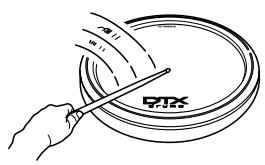
Snare/Tom
Just as on an acoustic snare, you can hit the drum pad (e.g., XP120SD illustrated below) in three different ways below. Keep in mind that the example XP120SD illustrated below is divided into three sections.
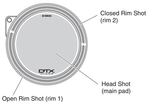
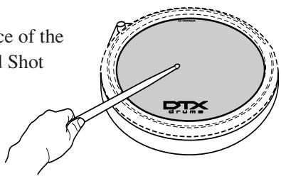
Head Shot
Hitting the main surface of the pad produces the Head Shot sound.
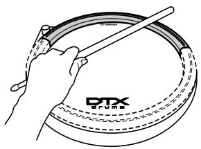
Open Rim Shot
Hitting the Rim section closest to you produces the Open Rim Shot sound.

Closed Rim Shot
Hitting the Rim section farthest from you produces the Closed Rim Shot sound.
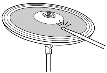
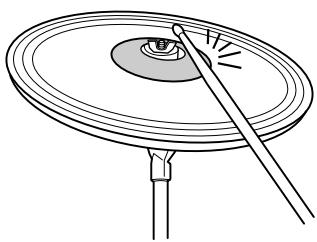
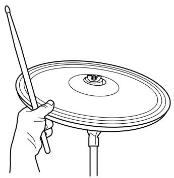
Hi-Hat Cymbal
As with an acoustic hi-hat cymbal, you can play the cymbal pad (e.g., RHH135 illustrated below) along with the Hi-Hat Controller (HH65, etc.) via the ways as illustrated below. Keep in mind that the example RHH135 illustrated below is divided into two sections.
Open/Close
In addition to the Foot Close sound obtained pressing the Hi-Hat Controller, you can hold and press the Controller down even more firmly (in the closed condition) for getting a "tighter" closed hi-hat sound.
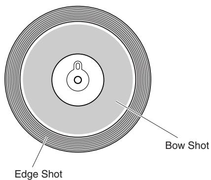
Bow Shot
Hitting the main surface of the pad (the bow section located between the cup and edge) produces the Bow Shot sound.
Edge Shot
Hitting the outside edge of the pad produces the Edge Shot sound.
Hi-Hat Splash
Pressing the Hi-Hat Controller then releasing it immediately produces the Hi-Hat Splash sound.
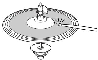
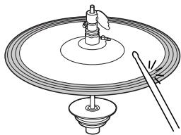
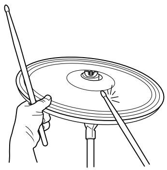
Ride Cymbal
As with an acoustic ride cymbal, you can play the cymbal pad (e.g., PCY155 illustrated below) via the various ways as illustrated below. Keep in mind that the example PCY155 illustrated below is divided into three sections.
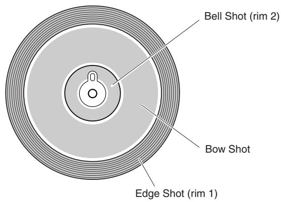
Bow Shot
Hitting the main surface of the pad (bow section located between the cup and edge) produces the Bow Shot sound.
Edge Shot
Hitting the outside edge produces the Edge Shot sound.

Bell Shot
Hitting the cup produces the Bell Shot sound.
Choke
Grabbing the edge of the Cymbal pad immediately after hitting it will stop the sound.
NOTE
- Depending on the voice assigned to the Edge section, the sound may not stop immediately.
Mute
Hitting the pad while holding the edge produces a muted sound.
Playing the DTX900
Now that your DTX900 is properly connected, it's time to make some music!
Hitting the Pads
While hitting the pads, move the MASTER slider or PHONES slider on the panel to raise the overall volume to a comfortable level.
+
MASTER PHONES CLICK ACCOMP
Selecting a Drum Kit
A 'Drum Kit' is a collection of drum sounds (or voices) that play when you hit the pads. Try selecting some of the Drum Kits and enjoy the variety of sounds and drum setups available.
Press the [DRUM KIT] button to enter the Drum Kit Select display.
If another display appears, press the [F1] PLAY button to call up the Drum Kit Select display.
![YAMAHA DTX-900 - Press the [DRUM KIT] button to enter the Drum Kit Select display. - 1](/content/2025/01/114986/images/97ab10ca905011b71d7299ac290be8ed4da46a198ae76d1e0e48dc6a8718cefc.jpg)
![YAMAHA DTX-900 - Press the [DRUM KIT] button to enter the Drum Kit Select display. - 2](/content/2025/01/114986/images/8c2fd729916c040ba36bf9422d1b2654319de208ab1c762da48e5b39dd9c4347.jpg)
① Drum Kit number
Indicates the current Drum Kit bank, number and its name. PRE: 01 - PRE: 50 are preset kits and USR: 01 - USR: 50 are user kits stored in internal flash ROM, while EXT-A: 01 - EXT-P: 99 are user kits stored in the external USB storage device connected to the USB TO DEVICE terminal.
② Drum Kit icon
Indicates the music genre of the current Drum Kit.
③ [SF1] VAR
When Bypass is turned off (the BYPASS indication is shown with white text in black VAR), the Variation Effect is applied to the Drum Kit sound. When Bypass is turned on (the BYPASS indication is shown with black text in white VAR), the Variation Effect is not applied to the Drum Kit sound.
④ [SF2] REVERB
When Bypass is turned off (the BYPASS indication is shown with white text in black REVERE ), the Reverb Effect is applied to the Drum Kit sound. When Bypass is turned on (the BYPASS indication is shown with black text in white REVERE ), the Reverb Effect is not applied to the Drum Kit sound.
⑤ [SF3] CHORUS
When Bypass is turned off (the BYPASS indication is shown with white text in black CHORUS), the Chorus Effect is applied to the Drum Kit sound. When Bypass is turned on (the BYPASS indication is shown with black text in white CHORUS), the Chorus Effect is not applied to the Drum Kit sound.
[SF4] BANK
⑦ [SF5] BANK
Use these buttons to change the Drum Kit Bank. (PRE, USR, EXT-A, EXT-B ... EXT-P)
2 Select the desired Drum Kit by using the [INC/YES] button, [DEC/NO] button or data dial.
Try out the different Drum Kits and select one Drum Kit you like.
NOTE
- Keep in mind that the example displays shown in this manual are for instruction purposes only, and may appear somewhat different from those on your instrument.
NOTE
- With the initial default settings, the Drum Kit number is shown also in the LED display.
- Some preset Drum Kits have Pad Songs and Drum Loop Voices that will start when the corresponding pad is hit.
- The Drum Kit icon can be changed by setting the Icon parameter in the display called up via [F6] OTHER [SF4] NAME (page 97).
- If identical voices are assigned to the same Channel-10 MIDI note numbers in both the newly selected kit and the previous kit, it is normal for voices for the corresponding pads to continue to play when the new drum kit is selected.
Adjusting the Volume by Using the Sliders
You can change the volume for each pad and adjust the overall balance of the Drum Kit by using the sliders on the front panel.
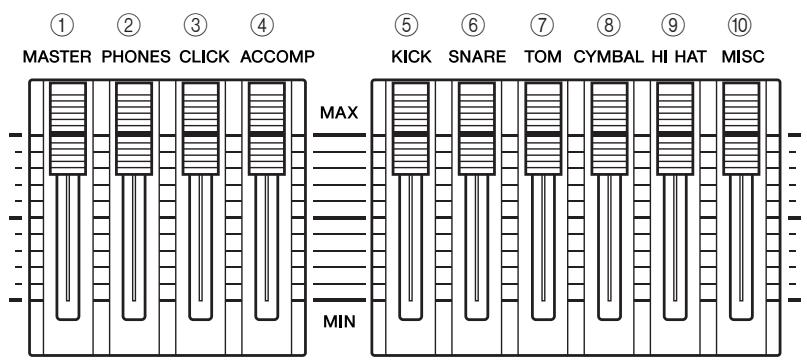
① MASTER slider
Adjusts the output volume of the stereo mix from the OUTPUT L/MONO and R-Jacks.
② PHONES slider
Adjusts the output volume of the stereo-mixed sounds for the PHONES jack. This is independent from the MASTER slider setting.
③ CLICK slider
Adjusts the output volume of the click sound.
④ ACCOMP slider
Adjusts the output volume of the accompaniment parts (those other than MIDI channel 10) in the Song.
⑤ KICK slider
Adjusts the volume of the bass drum. You can change the destination instruments or voices of which the volume is adjusted by setting the SliderSel parameter called up via [DRUM KIT] [F2] VOICE [SF4] OTHER.
⑥ SNARE slider
Adjusts the volume of the snare drum. You can change the destination instruments or voices of which the volume is adjusted by setting the SliderSel parameter called up via [DRUM KIT] [F2] VOICE [SF4] OTHER.
⑦ TOM slider
Adjusts the volume of the toms. You can change the destination instruments or voices of which the volume is adjusted by setting the SliderSel parameter called up via [DRUM KIT] [F2] VOICE [SF4] OTHER.
⑧ CYMBAL slider
Adjusts the volume of the cymbals. You can change the destination instruments or voices of which the volume is adjusted by setting the SliderSel parameter called up via [DRUM KIT] [F2] VOICE [SF4] OTHER.
⑨ HI-HAT slider
Adjusts the volume of the hi-hat cymbals. You can change the destination instruments or voices of which the volume is adjusted by setting the SliderSel parameter called up via [DRUM KIT] [F2] VOICE [SF4] OTHER.
10 MISC slider
Adjusts the volume of miscellaneous rhythm or percussion sounds – other than snare and bass drums, toms, hi-hats, and ride and crash cymbals. You can change the destination instruments or voices of which the volume is adjusted by setting the SliderSel parameter called up via [DRUM KIT] → [F2] VOICE → [SF4] OTHER.
Playing Along With the Click
Try playing the DTX900 along with the click (metronome). The DTX900 is equipped with a high-performance metronome that gives you a comprehensive variety of settings and allows you to create complex rhythms.
Start the Click (Metronome)
Press the [CLICK ON/OFF] button to start the click sound. The red lamp lights on the first beat of every measure when the click or a Song is playing. The other beats are indicated with a green light.
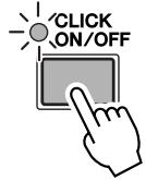
1st beat (red) Other beats (green)
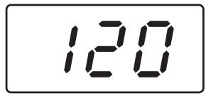
Tempo value
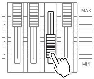
Setting the Click volume level
MASTER PHONES CLICK ACCOMP
NOTE
- The current Tempo value can be shown on the LED display by setting the LED Display parameter to "tempo" in the display called up via [UTILITY] [F1] GENERAL [SF5] OTHER.
Press the [CLICK ON/OFF] button again to stop.
You can adjust the volume of the click sound by moving the CLICK slider.
Changing the Tempo and Time Signature (Beat) of the Click
Press the [CLICK] button to enter the Click mode.
2 Press the [F1] PLAY button to call up the Click Play display, if necessary.
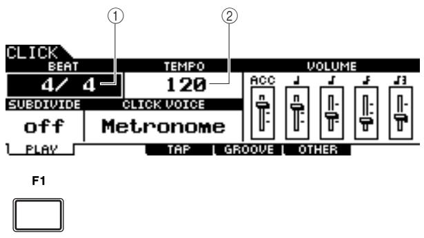
① BEAT (Time Signature)
Indicates the time signature of the Click. You can select one of the following values.
| Settings | 1/4 – 16/4, 1/8 – 16/8, 1/16 – 16/16 |
(2) TEMPO
Indicates the tempo value of the Click. You can set the value over the following range.
| Settings | 030 – 300 |
NOTE
- When MIDI Sync ([UTILITY] [F5] MIDI [SF2] SYNC MIDI Sync) is set to "MIDI," "MIDI" is displayed as the TEMPO value and cannot be set.
3 Move the cursor to the TEMPO or BEAT (Time Signature) by using the Cursor buttons, then set the value by using the [INC/YES] button, [DEC/NO] button or data dial.
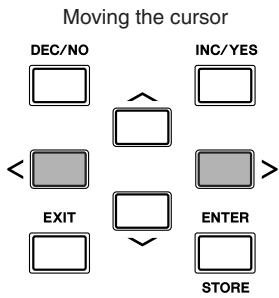
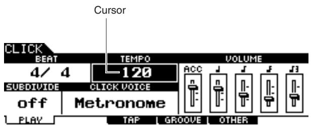
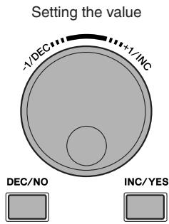
Tap Tempo
With the Tap Tempo Function, you can set the Song or click's tempo by manually tapping in the tempo on a pad. This lets you set whatever tempo you desire for playing or practicing. The Audition button can also be used to set the tempo instead of tapping on a pad.
Press the [CLICK] button to enter the Click mode.
2 Press the [F3] TAP button to call up the Tap display.

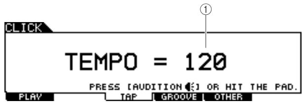
① TEMPO
Indicates the tempo value.
Settings
030-300
3 Tap on the pad at the tempo in which you want to play (or use the Audition button).
You can hit any of the pads. The tempo is detected from the timing at which you hit the pad, and is shown in the LED display and indicated as a TEMPO value in the LCD display. The Tempo value in the LED display will be replaced with the Drum Kit number in a few seconds after performing the Tap with the initial default status when shipped from the factory.
Tempo value
120
4 Press the [CLICK ON/OFF] button to hear your newly set tempo.
The tempo value will be applied to Song playback and Click playback immediately if you change the tempo during playback.
NOTE
- When the PadFunc parameter (page 126) is set to "tap tempo" in the display called up via [UTILITY] [F2] PAD [SF2] PAD-FUNC, the pad specified as source in this display can be used for the Tap Tempo function even if any display other than the Click Tap display is shown.
- When MIDI Sync ([UTILITY] [F5] MIDI [SF2] SYNC MIDI Sync) is set to "MIDI," "MIDI" is displayed as the TEMPO value and the Tap Tempo function is not available.
Playing Along With a Song
The DTX900 contains a wide variety of Preset Songs, organized into the following three categories.
Demo Songs
These Songs are created to showcase the high-quality sound of the DTX900.
Practice Songs
These Songs are created to help you practice in a wide variety of musical genres.
Pad Songs (page 93)
These Songs are created to be called up (during a performance, for example) by hitting a pad.
Try selecting among these and play along with them—they are effective tools that help you learn how to drum and master drumming techniques. The DTX900 conveniently lets you mute the drum part of a Song and have only the bass part sound during playback, so you can play the drum part yourself.
SongPlayback
Select one of the DTX900's Preset Songs and listen to it. The Preset Songs include accompaniment with keyboard, brass, and other voices as well as drum sounds. For a list of the Preset Songs, see the separate Data List booklet.
Press the [SONG] button to enter the Song mode.
![YAMAHA DTX-900 - Press the [SONG] button to enter the Song mode. - 1](/content/2025/01/114986/images/92cee0f383249dd6e9efad5195e2a09b0db8dc15e45a46af5c3053f4434cee20.jpg)
![YAMAHA DTX-900 - Press the [SONG] button to enter the Song mode. - 2](/content/2025/01/114986/images/4c04e2577e0db2d759464d8c4230f4a47334af3ddbaa0b34ec164085f953214c.jpg)
NOTE
- Keep in mind that the example displays shown in this manual are for instruction purposes only, and may appear somewhat different from those on your instrument.
2 Call up the Song Play display by pressing the [F1] PLAY button, if necessary.
![YAMAHA DTX-900 - Call up the Song Play display by pressing the [F1] PLAY button, if necessary. - 1](/content/2025/01/114986/images/63c6e707fbe6e2142b53d69ec2c8d0a1c2cf34d56cb346f5bee0642c4b0edb7c.jpg)
① Song number
Indicates the current Song number.
When a Preset Song is selected, one of the categories ("Demo," "Practice" and "Pad-Song") is shown at right of the Song number.
| Settings | PRE: 01 – PRE: 87, USR: 01 – USR: 50, EXT: 01 – EXT: 99 |
PRE: Preset Song
USR:UserSong
EXT: External Song saved in the root directory of the USB storage device as a Standard MIDI file (format 0).
② Song name
Indicates the name of the current Song.
③ Drum Kit
At the top of the display, the Drum Kit specified by the current Song is shown. When the "L" indication is shown (by pressing the [F6] KITLOCK button), the Drum Kit cannot be changed.
(4) [F6] KITLOCK
Press this button to turn the "L" indication (Kit Lock) on. In this status, the current Drum Kit cannot be changed by the Song data. When Kit Lock is turned off, the Drum Kit number will change to the one specified in the current Song:
- When a Song is selected.
- When playback of a Song reaches the end and stops automatically.
- When the beginning of the current song is called up by pressing the [▲] button.
When Kit Lock is turned on, the Drum Kit number is maintained, even if one of the operations above are performed.
3 After moving the cursor to the Song number, select the desired Song by using the [INC/YES] button, [DEC/NO] button or data dial.
Changing the Song calls up the Drum Kit specified by the new Song. When the "L" indication (Kit Lock) is turned on, the current Drum Kit will be maintained even if you change the Song number.
4 Press the [▶/■] (Playback/Stop) button to start the selected Song.
The lamp lights during Song playback.
![YAMAHA DTX-900 - Press the [▶/■] (Playback/Stop) button to start the selected Song. - 1](/content/2025/01/114986/images/73aed76ea50af2a20be99e3b914077608f94f3cf3be3af4ee8a818bdf02db7ff.jpg)
Press the [▶/■] (Playback/Stop) button again to stop playback.
Press the [▶/■] (Playback/Stop) button once more to resume playback from that point.
Playback From the Middle of the Song
To start playback of the Song midway through, set the desired location by using the controls below, then press the [▶/■] (Play) button. These operations can also be executed during playback.
| Forward | Press the [▶] (Forward) button. |
| Fast forward | Hold the [▶] (Forward) button. |
| Rewind | Press the [←] (Rewind) button. |
| Fast Rewind | Hold the [←] (Rewind) button. |
| Move to the top of the Song | Press the [▶] button. |
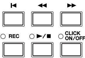
Fast Forward/Rewind
From the Song Play display, you can change the Song playback position by following the operations below.
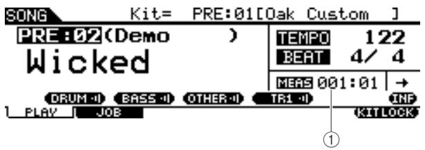
① MEAS (Measure)
Indicates the current position of the Song.
1 Move the cursor to MEAS (Measure).
2 Move forward or backward through the measures by using the [INC/YES], [DEC/NO] buttons and the data dial.
Repeat Playback
You can set repeated Song playback (the Song plays from beginning to end and repeats). When “→” is selected, the Song plays from beginning to end and stops automatically.
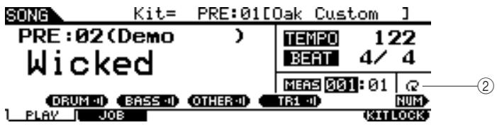
② Repeat
| Settings | (Normal playback) (Repeated playback) |
NOTE
- When the cursor is located at MEAS, the NUM icon is shown at the menu corresponding to the [SF6] button. In this condition, you can use the [SF1] – [SF5] and [F1] – [F5] buttons as number buttons by pressing the [SF6] NUM button. For details, see page 14.
NOTE
- The Song Repeat setting on the [F1] PLAY display is temporary and cannot be maintained as data. If you want to apply the Repeat setting to the Song data, set the Repeat parameter in the display called up via [SONG] [F2] JOB [SF1] SONG "03:Song Name, Tempo, Repeat."
- Preset Songs and User Songs include the Repeat setting. This is why the Repeat setting shown on the [F1] PLAY display is changed when a certain Preset Song or User Song is selected. On the other hand, SMF Songs (EXT: 01 - 99) on the USB storage device include no Repeat setting. This is why the Repeat setting shown on the [F1] PLAY display is maintained even when a certain SMF Song is selected.
Adjusting the Volume of the Song Accompaniment
You can adjust the volume of the Song accompaniment part (other than drum part) by moving the ACCOMP slider on the front panel. Use both the ACCOMP slider and the MASTER slider (overall volume of Song and pads) to adjust the balance between the Song and your drum part.
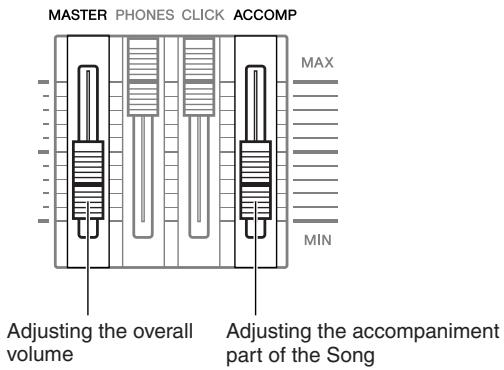
Changing the Tempo of the Song
You can change the tempo of the current Song by following the operations below.
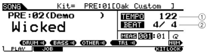
① TEMPO
Indicates the current tempo.
Settings
030-300
② BEAT (Time Signature)
Indicates the time signature of the Click sound.
Settings
1/4-16/4,1/8-16/8,1/16-16/16
1 Use the Cursor buttons to move the cursor to the location to be edited.
2 Set the value by using the [INC/YES], [DEC/NO] buttons and the data dial.
NOTE
- The tempo value can be shown on the LED display by setting the LED Display parameter in the display called up via [UTILITY] [F1] GENERAL [SF5] OTHER.
Each of the Preset Songs includes the original tempo setting. This tempo value is called up automatically when the Song is selected and the top of the Song is called up by pressing the [ ] button. - If you want to maintain the tempo value even when you change the Preset Song, set the Tempo Link parameter to "off" in the display called up via [UTILITY] [F1] GENERAL [SF5] OTHER.
- The Song Tempo value on the [F1] PLAY display is temporary and cannot be maintained as data. If you want to apply the Tempo value to the Song data, set the Tempo parameter in the display called up via the [SONG] [F2] JOB [SF1] SONG "03: Song Name, Tempo, Repeat."
Song Part Mute Setting
The Mute function lets you turn on/off the rhythm (drum & percussion sound) part, bass part and other accompaniment part individually, or turn selected tracks on/off. For example, you could mute the rhythm part to play rhythms yourself using the pads, or you could play along with just the bass part sounding, or you could jam with an actual bass player with all other accompaniment parts enabled.
The Mute status can be confirmed by checking the tabs corresponding to the [SF1] - [SF3] buttons. A part name indication of "DRUM," "BASS," and "OTHER" in black characters means that the corresponding part is muted while a part name indication in white characters means that the corresponding part is turned on. Pressing these buttons toggles part playback on and off (Mute).
Mute status
Example: DRUM part (rhythm part)
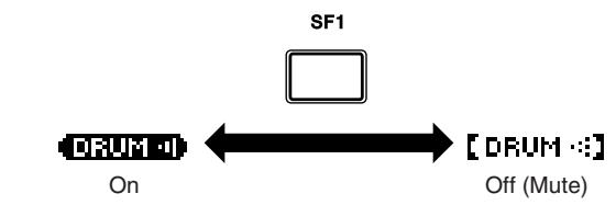
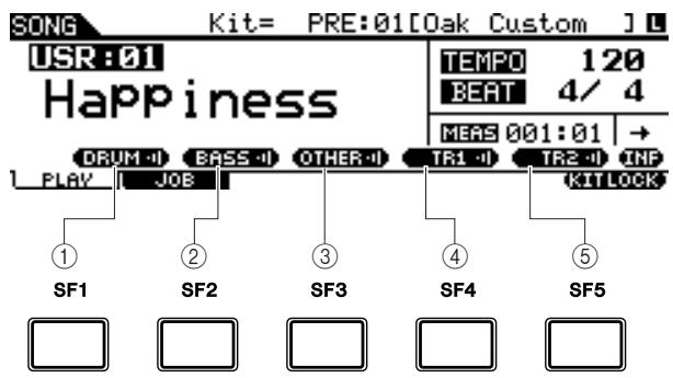
① [SF1] DRUM
Pressing this button toggles DRUM part playback on and off (Mute). This button does not affect the same part included in Track 2 of the Song.
(2) [SF2] BASS
Pressing this button toggles BASS part playback on and off (Mute).
(3) [SF3] OTHER
Pressing this button toggles OTHER part playback on and off (Mute).
④ [SF4]TR1(Track 1)
Pressing this button toggles Track 1 playback on and off (Mute).
⑤ [SF5] TR2 (Track 2)
Pressing this button toggles Track 2 playback on and off (Mute).
NOTE
- The Preset Songs consist of multiple parts (MIDI channels) and have been recorded to a single track (Track 1). For details about the Song data structure (relationship between parts and tracks), see page 67.
- When no data is recorded to Track 1 or 2, the corresponding tab ("TR1" or "TR2") is not shown in the display. When a Preset Song is selected, "TR2" is not shown in the display because no data is recorded to Track 2 for all the Preset Songs.
Tracks TR1 and TR2 of an external Song (EXT: 01 - 99) saved to a USB storage device cannot be muted.
Creating a Drum Kit
The DTX900 lets you create your own original Drum Kit by assigning your favorite Drum Voice to each pad and setting its tuning, pan, decay, reverb, etc.
Terminology
- Drum Voice
A Drum Voice is an percussion/drum instrument assigned to each pad. Assigning Drum Voices to pads makes up a Drum Kit.
- Drum Kit
A Drum Kit is a collection of Drum Voices assigned to the individual pads. Selecting a Drum Kit assigns the Drum Voice(s) to each pad.
Voice Set
When you connect a stereo pad (referred to as a “two-zone pad” and “three-zone pad”) to the Trigger Input jack (pages 12 and 60), a different Drum Voice is triggered by the pad depending on the section you hit. A set of Voices that can be triggered from a single pad is referred to as a “Voice Set.” You can assign a Voice Set to each pad (Trigger Input jacks).
Here, select a Voice Set for each of pads (Trigger Input jacks) to create your original Drum Kit.
Press the [DRUM KIT] button to enter the Drum Kit mode, then press the [F1] PLAY button as necessary.
2 Select the desired Drum Kit by using the data dial, [INC/YES] and [DEC/NO] buttons.
A good idea is to select a Drum Kit that is close in sound to the type of kit you intend to create. Here, select "PRE: 01."
3 Press the [F2] VOICE button, then the [SF1] SELECT button to call up the display shown below.
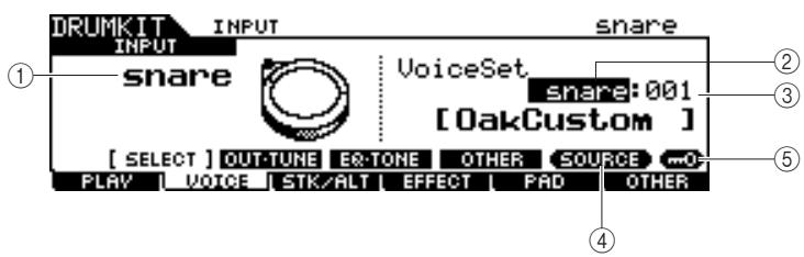
① INPUT or SOURCE
When "INPUT" is shown here, the Trigger Input jack (pages 12 and 60) is currently selected for editing, and you can change it to the desired one to which you want to assign the Voice Set. When "SOURCE" is shown here, the Trigger Input Source (page 61) is currently selected for editing, and you can change it to the desired one to which you want to assign the Voice.
② Voice Set category
Preset Voice Sets are divided into the following categories, which you can select here.
| Settings | kick, snare, tom, cymbal, hihat, perc, efect |
NOTE
- The Voice Set does not include the User Voice assignment.
③ Voice Set number
You can select the Voice Set number here from the Voice Set category selected above. In the INPUT display, an asterisk (*) will appear when the Voice set at each Trigger Input source is different from that in the current Voice Set.
| Settings | 0 – 127 (0: No Assign) |
(4) [SF5] SOURCE or INPUT
Pressing this button toggles the indication at the top left corner between INPUT (Trigger Input jack) and SOURCE (Trigger Input Source).
⑤ [SF6] Input Lock
Pressing this button turns the Input Lock ("L" indicator at the right corner of the display) on or off. Normally, the Trigger Input jack or Trigger Input Source to be edited can be determined by hitting the corresponding pad. If you want to maintain it even if you hit any pad, press this button to turn the Input Lock ("L" indicator) on.
4 When “INPUT” is shown at the tab corresponding to the [SF5] button, press the [SF5] button so that “INPUT” is shown at the right corner of the display.
5 Select the Trigger Input jack by hitting the corresponding pad or by moving the cursor to the INPUT then using the data dial, [INC/YES] and [DEC/NO] buttons.
The corresponding illustration appears.
6 Move the cursor to the Voice Set category, then select the desired category by using the data dial, [INC/YES] and [DEC/NO] buttons.
7 Move the cursor to the Voice Set number, then select the desired number by using the data dial, [INC/YES] and [DEC/NO] buttons.
The [E] indicator
When changing the value of the parameter in the Drum Kit mode, the [E] (Edit) Indicator will appear on the top left corner of the LCD display. This gives a quick confirmation that the current Drum Kit has been modified but not yet stored. To store the current edited status, follow the instructions on the next page.
![YAMAHA DTX-900 - The [E] indicator - 1](/content/2025/01/114986/images/8d248b4b484a2d50651e50925da655ce2814cb2822b49dae1d957a518c0bbfca.jpg)
Storing the Edited Drum Kit
To store the original Drum Kit you've created thus far, follow the instructions below.
NOTICE
- When the [E] indicator is shown (meaning that the current Drum Kit has been modified but not yet stored), all your edits will be lost when selecting a different Drum Kit. Keep in mind that the Drum Kit may also be inadvertently changed by selecting a different Song. Make sure to store the edited Drum Kit before selecting a different Drum Kit or Song.
Press the [ENTER/STORE] button.
The following display appears.
![YAMAHA DTX-900 - Press the [ENTER/STORE] button. - 1](/content/2025/01/114986/images/5eb435951fb25b75fc3d53a3400239736384552cb33e32d474e3082377419780.jpg)
2 Select the destination Drum Kit memory.
First, move the cursor to the Drum Kit bank then select the desired one from "USR" and "EXT-A" through "EXT-P." When you want to select a Drum Kit from "EXT-A" through "EXT-P," make sure to connect the appropriate USB storage device to the USB TO DEVICE terminal. Second, move the cursor to the Drum Kit number, then select the desired one.
3 Press the [ENTER/STORE] button again.
The display prompts you for confirmation. To cancel the Store operation, press the [DEC/NO] button.
4 Press the [INC/YES] button to execute the Store operation.
NOTICE
- Never attempt to turn off the power while the message "Please keep power on" is shown; all data you have created may be lost. Only use the voltage specified as correct for the DTX900.
Recording Your Drum Performance to a Song
In this section, you'll learn how to record your performances and create Songs using the Song Recording features.
Recording System
- Recording can be done with any of the User Songs. You cannot record your performance to Preset Songs.
Each User Song contains two tracks available for recording. Recording can be done to one of the tracks at a time. - A recorded Song doesn't contain recordings of the audio sounds of the drums, but rather the performance information or data of precisely when and how each pad was hit as MIDI events. Also, MIDI data produced by an external MIDI keyboard connected to the MIDI IN connector can be recorded as well as MIDI sequence data received via the USB TO HOST terminal from your computer.
- The recorded Song data is not audio data but MIDI sequence data, allowing you to freely change the tempo, Drum Kit and Drum Voice when playing back the recorded Song.
- The tempo and time signature (Beat parameter) can be recorded only as the header data. During Song recording, these cannot be recorded, although the tempo can be changed.
For more information about the Song data structure, see page 67.
Recording Methods
Realtime Recording
Generally, MIDI sequencers provide two methods of recording: Realtime Recording and Step Recording. The DTX900 provides only Realtime Recording. This method lets you record the performance data as it is played, allowing you to capture all the nuances of an actual drum performance.
Replace and Overdub (Loop)
When "replace" is selected as Recording Type in the REC STANDBY display (called up via the [REC] button in the Song mode), you can record your drum performance to a track which contains no data. Keep in mind that you cannot record your drum performance to a track which contains any data. If you want to replace your performance data with already-recorded data, use the Clear Track Job (page 101) or Clear Song Job (page 99) before recording.
When "overdub" is selected as the Recording Type in the REC STANDBY display (called up via the [REC] button in the Song mode), loop recording is enabled, allowing you to add more performance data to a track that already contains data. The first 'lap' in the loop recording is kept, and other parts you play in the successive laps are added on top. This method lets you build up complex phrases.
Two Tracks and Multi-channel Recording
The built-in sequencer offers two sequence tracks (Tr1 and Tr2) for each Song, and you can use them for both recording and playback. Each track can contain any event on any MIDI channel (1 to 16). This means you can connect a keyboard to the MIDI IN connector of the DTX900 and (with the help of a keyboard playing friend) record both the keyboard performance and your Drum Kit playing in real time onto a single track.
If you merge contents on both tracks into one track and empty the other track by using the Mix Track Job (page 100), you can record the new data to the empty track separately.
Recording Your Drum Performance to a Song
1 Select the desired Drum Kit in the Drum Kit mode.
2 Press the [SONG] button to enter the Song mode then press the [F1] PLAY button to call up the Song Play display as necessary.
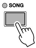
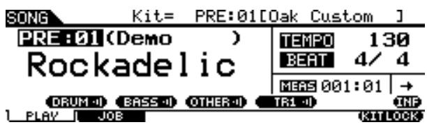
3 Press the [F6] KITLOCK button so that the “L” indicator appears at the top right of the display.
This step is necessary because selecting a Song may change a Drum Kit.
4 Select a User Song to be recorded by using the [INC/YES], [DEC/NO] buttons and the data dial.
Make sure to select a User Song that contains no data and does not indicate "TR1" and "TR2" in the display.
Press the [REC] button to call up the REC STANDBY display.
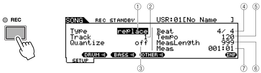
① Type (Recording Type)
Determines the Recording Type. You can select "replace" or "overdub." For details, see page 43.
Settings replace, overdub
② Track (Recording Track)
Determines the track to be recorded.
Settings 1,2
③ Quantize
Determines the Record Quantize value. Record Quantize automatically aligns the timing of notes as you record. When the cursor is located at the Quantize value, the note type icon is shown at the menu corresponding to the [SF6] button. In this condition, you can call up a list of the note type icons by pressing the [SF6] button, then select the desired item from the list.
| Settings | When “3/8”, “6/8”, “9/8”, “12/8” or “15/8” is selected: off, 16th note triplet, 16th note, 8th note triplet, 8th note, 1/4 note, dotted 1/4 note When another value is selected: off, 16th note triplet, 16th note, 8th note triplet, 8th note, 1/4 note triplet, 1/4 note |
NOTE
- When a Preset Song is selected, this step may not be necessary, since pressing the [REC] button selects an empty User Song. If all the User Songs contain data (if there is no empty Song), the message "Seq data is not empty" appears, indicating that you cannot call up the REC STANDBY display by pressing the [REC] button in step 5. In this case, step 4 here is necessary.
How Quantize Works (example)
Recorded notes were not played in time.
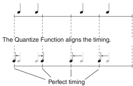
④ Beat (Time Signature)
Determines the time signature of the Song.
| Settings | 1/4 – 16/4, 1/8 – 16/8, 1/16 – 16/16 |
⑤ Tempo
Determines the tempo of the Song.
| Range | 030 – 300 |
(6) MeasLength (Measure Length)
Determines the length of the Song to be recorded.
| Range | 001 – 999 (differs depending on the status of the User Song and starting measure of recording) |
(7) Meas (Measure)
Determines the measure from which recording starts.
| Settings | 001 – 999 (differs depending on the status of the User Song) |
6 Set the Type parameter to "replace" by using the [INC/YES], [DEC/NO] buttons and data dial.
7 Move the cursor to "Track," then select a track to be recorded.
Set other parameters as necessary, such as Tempo, Beat (time signature), Measure (from which recording starts) and Quantize.
8 Turn [CLICK ON/OFF] on if you want to use the Click sound.
For details about the Click, see page 32.
9 Press the [▶/■] (Play/Stop) button to start recording.
10 After recording stops automatically when the last measure (specified by the Measure Length) is reached, press the [▶/■] (Play/Stop) button to hear the newly recorded Song.
You can stop recording at the middle of the Song by pressing the [▶/■] button.
NOTICE
- Be careful to avoid turning the power off or disconnecting the AC adaptor during recording; otherwise your recorded data will be lost.
11 Save the recorded Song to a USB storage device.
NOTICE
- The recorded Song data resides temporarily in DRAM (page 76). Because data contained in DRAM is lost when the power is turned off, you should always save any data residing in DRAM to a USB storage device before turning off the power.
NOTE
- When you select an already-recorded Song, you cannot set the Measure Length to a value greater than that of the selected Song. If you need to set a greater Measure Length, add measures to the Song manually by using the Create Measure Job (page 102) before recording.
Recording Additional Notes to an Already-recorded Track (Overhub)
Use the Overdub recording method when you want to add more data to a track that already contains data. The Overdub Recording procedure is almost the same as Replace except that the Record type is set to "overdub" and you need to press the [▶/■] (Play/Stop) button when you want to stop recording.
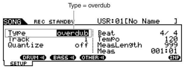
When the song reaches the end of the last measure, it will automatically start again from the beginning and new data will be added to the track's previous data.
Recording Along With the Preset Song
Although your drum performance cannot be recorded to a Preset Song, you can add your own drum performance data to a Preset Song by copying the Preset Song data to a User Song.
1 Select an empty User Song (containing no data) in the Song mode.
Note that the "TR1" and "TR2" indications are not shown in the display when an empty User Song is selected.
2 Press the [F2] JOB button followed by the [SF1] SONG button to call up the SONG JOB SELECT display.
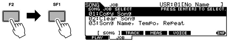
3 Move the cursor to "01: Copy Song" then press the [ENTER/STORE] button to call up the Copy Song Job display.
This Job lets you copy the source Song (specified in this Job display) to the current Song.
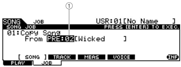
① Song bank and number
Indicates the bank number and name of the source Song.
4 Select the desired Preset Song as the copy source then press the [ENTER/STORE] button.
The display prompts you for confirmation. To cancel the Copy Song operation, press the [DEC/NO] button.
![YAMAHA DTX-900 - Select the desired Preset Song as the copy source then press the [ENTER/STORE] button. - 1](/content/2025/01/114986/images/a78030f9f106a1354e5fd0551211f91c9538fda5bf72e63e45092d04c045b74b.jpg)
5 Press the [INC/YES] button to execute the Copy Song operation.
6 Press the [REC] button to call up the REC STANDBY display.
![YAMAHA DTX-900 - Press the [REC] button to call up the REC STANDBY display. - 1](/content/2025/01/114986/images/7b6f3c0410ae33bad9a8b0c0b5043324e0cba457546ef40b0ff04b7a3d0f4bdf.jpg)
![YAMAHA DTX-900 - Press the [REC] button to call up the REC STANDBY display. - 2](/content/2025/01/114986/images/3bc323c93b4fbbe290b6c4446105f62f16182510e2a5f227662e41dc9d34c56b.jpg)
7 Move the cursor to "Type," then set this parameter to "replace."
8 Move the cursor to "Track," then set this parameter to "2."
Because the Preset Song data is recorded only to track 1, you can record your drum performance to track 2 along while track 1 plays back.
9 Press the [SF1] DRUM button to mute the drum part of the Preset Song data.
![YAMAHA DTX-900 - Press the [SF1] DRUM button to mute the drum part of the Preset Song data. - 1](/content/2025/01/114986/images/dfa2763ffdab3e4fd33fe337f09999ee36cefd9be1d87dfdd7ae78c8d27c0abf.jpg)
10 Press the [▶/■] (Play/Stop) button to start recording.
11 After recording stops automatically when the last measure is reached, press the [▶/■] (Play/Stop) button to hear the newly recorded Song.
You can stop recording at the middle of the Song by pressing the [/] button.
NOTICE
- Be careful to avoid turning the power off or disconnecting the AC adaptor during recording; otherwise your recorded data will be lost.
12 Save the recorded Song to a USB storage device.
Re-recording a Track After Clearing
To record again, use the following procedure to clear previously recorded data in the track, then try recording again.
7 With the User Song to be re-recorded selected, press the [F2] JOB button followed by the [SF2] TRACK button in the Song mode to call up the TRACK JOB SELECT display.
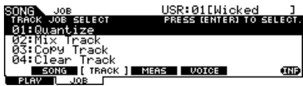
2 Move the cursor to "04: Clear Track," then press the [ENTER/STORE] button to call up the Clear Track Job display.
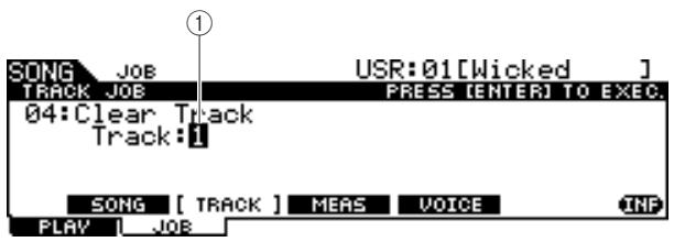
① Track
Indicates the track to be cleared.
3 Select a track to be cleared.
If you have copied the Preset Song data to the User Song and then recorded your drum performance to track 2, select "2" here.
4 Press the [ENTER/STORE] button.
The display prompts you for confirmation. To cancel the Clear Track operation, press the [DEC/NO] button.
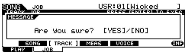
5 Press the [INC/YES] button to execute the Clear Track operation.
The data recorded to the specified track will be erased.
6 Re-record your drum performance to the cleared track.
Follow the instructions on page 44.
Assigning a Name to a User Song
You can assign an original name to a User Song.
7 With the desired User Song selected, press the [F2] JOB button followed by the [SF1] SONG button in the Song mode to call up the SONG JOB SELECT display.
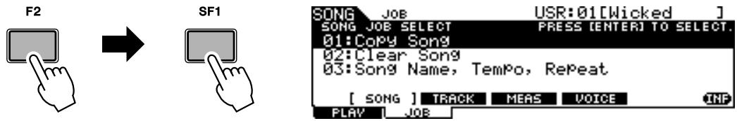
2 Move the cursor to "03: Song Name, Tempo, Repeat" then press the [ENTER/STORE] button to call up the Job display.
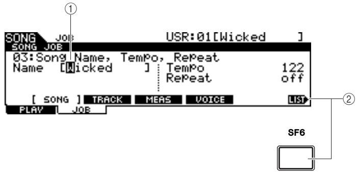
① Name
Determines the Song name, which can contain up to 10 characters. For detailed instructions on naming, refer to "Basic Operation" on page 15.
② [SF6] LIST
When the cursor is located at Name, this [LIST] icon appears at the right bottom of the display indicating that you can call up the Character List display by holding the [SF6] button. For details, see page 15.
3 Enter the Song name by following the instructions on page 15.
You can call up the character list by pressing the [SF6] LIST button, then select the desired one from the list.
Using the Groove Check Function
Another highly useful feature of the DTX900 is the Groove Check function. As you play along with a song or the click, Groove Check compares your timing with the song or click playback and lets you know how accurate your playing is. The related Rhythm Gate function—in which the sound is cancelled if your timing is off—also provides a great way for you to improve your technique.
NOTE
Groove Check can only be used during song or click playback, and only from the Groove Check display called up via [CLICK] [F4] GROOVE [SF1] G.CHECK, while Rhythm Gate can only be used during song or click playback, and only from the Rhythm Gate display called up via [CLICK] [F4] GROOVE [SF2] R.GATE.
Setting the Check Timing
This section describes how to specify the note timing to which the Groove Check and Rhythm Gate is applied.
Press the [CLICK] button to enter the Click mode.
2 Press the [F4] GROOVE button, then the [SF3] SETTING button.
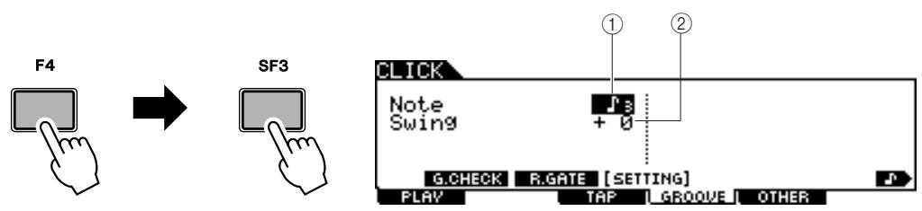
① Note
Determines the note timing to which Groove Check and Rhythm Gate are applied.
| Settings | When “3/8,” “6/8,” “9/8,” “12/8” or “15/8” is selected: whole note, dotted 1/4 note, 8th note, 16th note When another value is selected: whole note, 1/4 note, 8th note, 16th note, 8th note triplet |
② Swing
This parameter is available only when 8th note triplet is selected in the Note parameter. This parameter lets you specify the third note timing of the triplet as correct. In other words, this determines how your swing feel will be evaluated with Groove Check.
| Range | -39 – 0 – +39 0 (standard): Assumes that the correct timing is exactly at the third note of the triplet. -39 (minimum): Assumes that the correct timing is close to the third note at 16th note resolution. +39 (maximum): Assumes that the correct timing is close to the fourth note at 16th note resolution. |
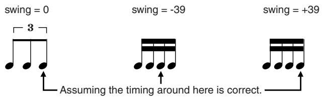
3 Move the cursor to the Note parameter by using the Cursor buttons, then select the desired note type by using the [INC/YES], [DEC/NO] buttons and data dial.
4 If the 8th note triplet is selected in step 3, move the cursor to the Swing parameter, then select the desired value.
Trying Out Groove Check
1 Select the desired Song (if you are using a Song).
2 Press the [CLICK] button to enter the Click mode, then set the Note and Swing parameters by following the instructions on page 50.
3 Press the [F4] GROOVE button, then the [SF1] G.CHECK button to call up the Groove Check display.

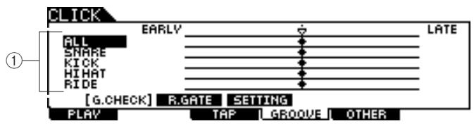
① Trigger Input 1 - 5
Here, you can set which pads (signals received via the Trigger Input jacks) will be monitored by Groove Check. Any (or all) pads can be selected, and up to five different pads can be monitored at once.
The "ALL" indication shows the result for all sounds (from all pads). The "NO ASGN" indication means no pad is selected. Lines showing other values indicate the result for the signal received via the corresponding Trigger Input jack.
Settings
NO ASGN, SNARE ... PAD15, ALL
4 Move the cursor to the Trigger Input, then select the desired one.
5 After the setup is completed, start the selected Song or Click sound, then play the drum pads along with playback.
Groove Check starts as soon as you hit the drum pad. The result for each hit (accuracy of the hit timing) is shown in the display in real time.
6 Stop playback then confirm the result of the Groove Check.
For details on the Groove Check display indications, see below.
Groove Check Results
In the Groove Check display, you can view the result of the check and see how accurate your timing is in real time. With the center line being correct timing, hits indicated at the left are early, and hits on the right are late. For details on each indication, see below.
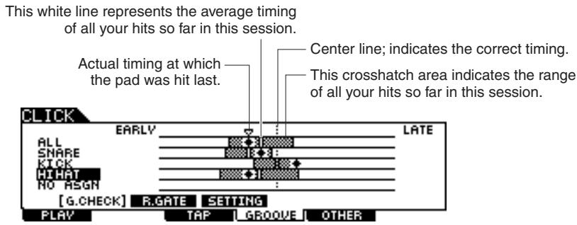
NOTE
- The interval between the left end (EARLY position) and the right end (LATE position) is equivalent to the length of a 16^th note.
Trying Out Rhythm Gate
The Rhythm Gate function lets you check the accuracy of your hit timing more finely and strictly. The sound is produced only when you hit at the correct (allowable) timing, which can be specified beforehand.
1 Select the desired Song (if you are using a Song).
2 Press the [CLICK] button to enter the Click mode, then set the Note and Swing parameters by following the instructions on page 50.
3 Press the [F4] GROOVE button, then the [SF2] R.GATE button to call up the Rhythm Gate display.
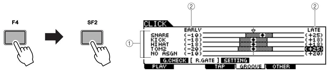
① Trigger Input 1 - 5
Here, you can set which pads (signals received via the Trigger Input jacks) will be monitored by Rhythm Gate. Any (or all) pads can be selected, and up to five different pads can be monitored at once.
The "ALL" indication shows the result for all sounds (from all pads). The "NO ASGN" indication means no pad is selected. Lines showing other values indicate the result for the signal received via the corresponding Trigger Input jack.
Settings
NO ASGN, SNARE ... PAD15, ALL
② Rhythm Gate Range
The crosshatch bar graph which indicates the hit timing range (regarded by Rhythm Gate as correct) is specified by setting the EARLY value and LATE value for each Trigger Input. From this display, the pad sound is produced only when hitting the pad within this timing window.
Range
-59-+59
NOTE
- This parameter can be set in 1/120 of a 16^th note. The distance from the left edge to the right edge of the display will be equivalent to length of 16^th note.
4 Move the cursor to the Trigger Input, then select the desired one.
When "ALL" is selected for any one of the lines, no other lines can be used.
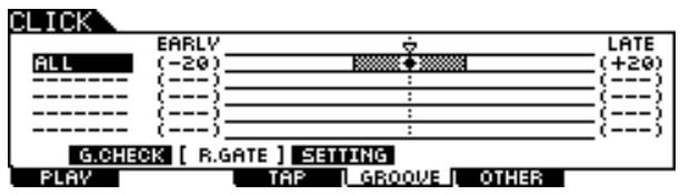
5 Move the cursor to the EARLY or LATE column, then set the allowable range by using the [INC/YES], [DEC/NO] buttons and data dial.
According to the value set here, the Rhythm Gate range (crosshatch bar) becomes wider or narrower.
6 After the setup is completed, start the selected Song or Click sound, then play the drum pads along with playback.
The Rhythm Gate starts as soon as you hit the drum pad. The result for each hit (accuracy of the hit timing) is shown in the display in real time.
7 Stop playback, then confirm the result of the Rhythm Gate.
For details on the Rhythm Gate display indications, see below.
Rhythm Gate Results
In the Rhythm Gate display, you can view the result of the check and see how accurate your timing is in real time. With the center line being correct timing, hits indicated at the left are early, and hits on the right are late. For details on each indication, see below.
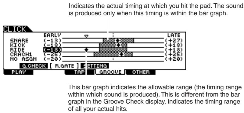
Saving the Created Data to a USB Storage Device
The File mode provides tools for transferring data between the instrument and the USB storage device connected to the USB TO DEVICE connector. This section describes how to save all the data (including Drum Kit, Drum Voice, Song, and Trigger Setup, etc.) to a USB storage device as a single file and load it from the device to the instrument.
NOTE
- For details about USB storage devices, see page 21.
File/Folder Selection
The illustrations and instructions below show you how to select files and folders on the USB storage devices within the File mode.
Select the File Type (page 113) from the TYPE column, then press the Cursor [>] button to move the cursor to the File/ Directory box at the right section in the display.
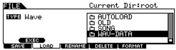
To return to the next highest level, press the [EXIT] button.


To go to the next lowest level, highlight the desired folder and press the [ENTER/STORE] button.
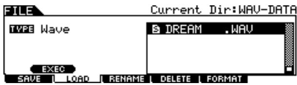
Select the directory or file by using the [INC/DEC], [DEC/NO], Cursor [] / [] buttons and data dial.
Saving the Created Data to a USB Storage Device
The Save operation can be done via various methods, such as saving all data as a single file or saving a specified type of data (e.g., only Drum Kits) as a single file. This section describes instructions on saving all the data you created in each mode of the DTX900 to a USB storage device as a single file.
After connecting the USB storage device, follow the instructions below.
Press the [FILE] button to enter the File mode.
2 Press the [F1] SAVE button to call up the Save display.
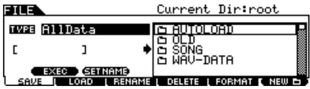
3 Move the cursor to the TYPE parameter, then set the File type to "AllData" by using the data dial or the [INC/YES] and [DEC/NO] buttons.
4 Move the cursor to the file name input location, then input a file name.
For detailed instructions on naming, refer to page 15 in the Basic Operation section. You can call up a convenient character list for easier name entry by pressing the [SF6] button.
Press the Cursor [>] button to move the cursor to the file/directory select box, then select a destination directory.
This step is necessary if you have created a directory as destination on the USB storage device. This is step is not necessary if you want to save the file to the root directory.
6 Press the [SF1] EXEC to execute the Save operation.
If you are about to overwrite an existing file, the display prompts you for confirmation. Press the [INC/YES] button to execute the Save operation to overwrite the existing file, or press the [DEC/NO] button to cancel it, then enter the file name again.
After the data has been saved, a "Completed" message appears and operation returns to the original display.
NOTICE
While the data is being saved, make sure to follow these precautions:
- Never remove or eject the media from the device (USB storage).
- Never unplug or disconnect any of the devices.
- Never turn off the power of the DTX900 or the relevant devices.
NOTE
- If you want to call up a sub directory, move the cursor to the desired directory then press the [ENTER/STORE] button.
Loading a File Saved to a USB Storage Device
This section describes instructions on loading a file saved to a USB storage device as an "AllData" file.
NOTICE
- Loading a file (extension: T3A) to the DTX900 automatically erases and replaces all existing data in the User memory. Make sure to save any important data to a USB storage device before performing any Load operations.
Press the [FILE] button to enter the File mode.
2 Press the [F2] LOAD button to call up the Load display.
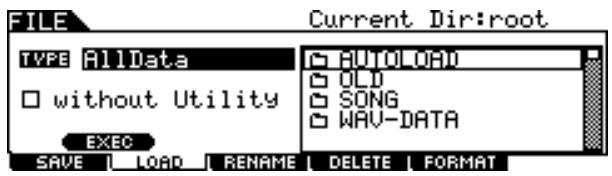
3 Move the cursor to the TYPE parameter, then set the File type to "AllData" by using the data dial or the [INC/YES] and [DEC/NO] buttons.
4 Press the Cursor [>] button to move the cursor to the file/directory select box, then select the desired file to be loaded.
If the file is saved under any directory, select the directory including the desired file, then press the [ENTER/STORE] button to find the desired file.
5 Press the [SF1] EXEC to execute the Load operation.
After the data has been loaded, a "Completed" message appears and operation returns to the original display.
NOTICE
While the data is being loaded, make sure to follow these precautions:
- Never remove or eject the media from the device (USB storage).
- Never unplug or disconnect any of the devices.
- Never turn off the power of the DTX900 or the relevant devices.
Basic Structure of the DTX900
This section describes the internal design of the DTX900 so that you can fully take advantage of the advanced and convenient functions of this instrument. Take a few moments here to understand how trigger signals are generated and transferred to the DTX900 when you hit the pads and how the sound is produced.
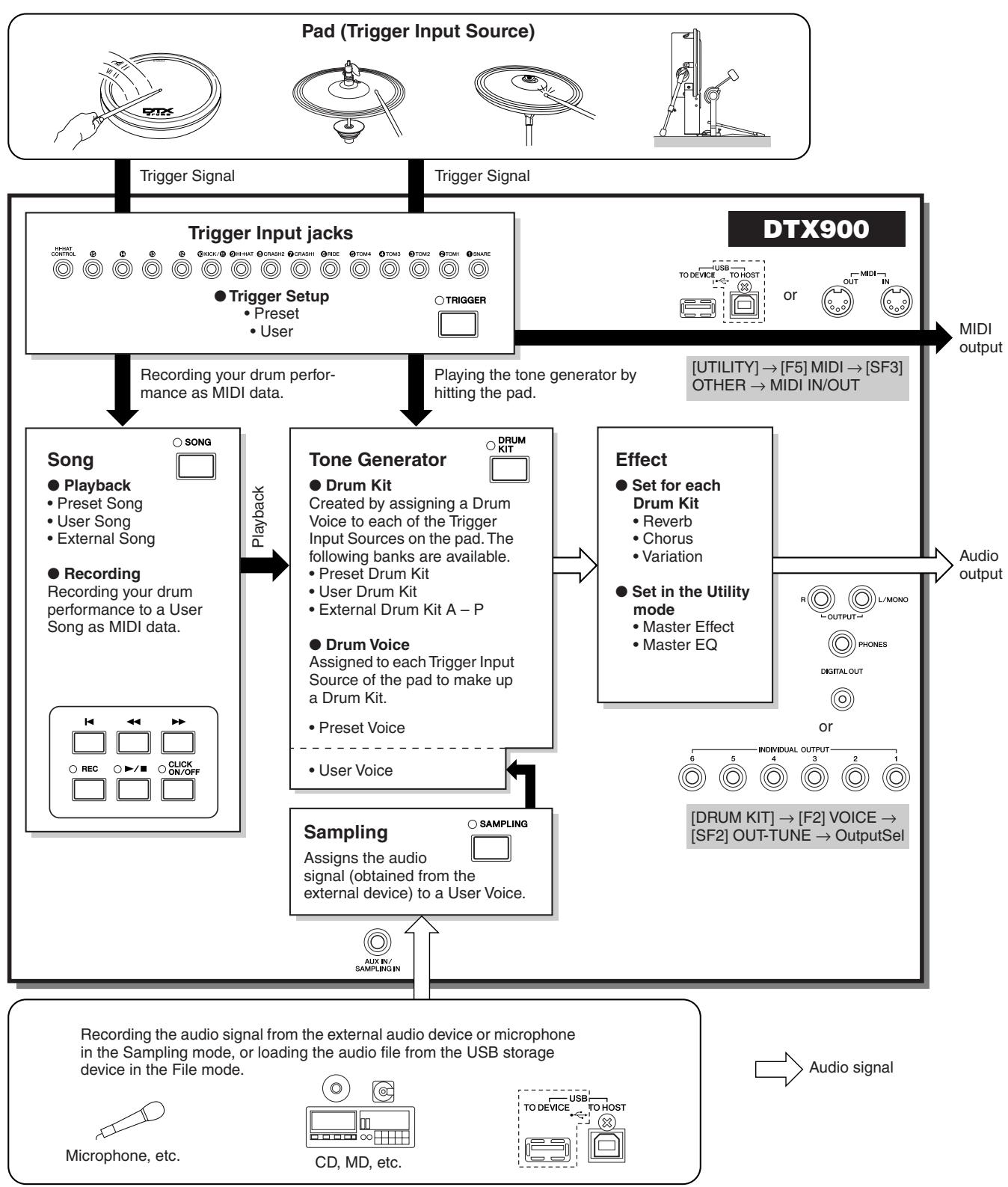
The Functional Blocks
Pads (Trigger Input Sources) and Trigger Signals
Hitting the pad produces a trigger signal which includes information about how strongly you hit the pad and what section of the pad you hit. The signal is transmitted via the cable and Trigger Input jack (pages 12 and 60) to the DTX900. The corresponding drum sound is triggered in the Tone Generator Block by this trigger signal. One trigger signal triggers one Drum Voice when setting the pad to sound only a single sound at a time. One pad generates one type of trigger signal or multiple types of trigger signals according to the pad model, what section of the pad you hit, how you play the pad and the particular pad settings. The pad generating the trigger signal may be also referred to as "Trigger Input Source."
Mono pads generating one type of trigger signal
Mono pads such as the TP65 drum pad and PCY65 cymbal pad can generate and transmit only one type of the trigger signal to the DTX900 regardless of where on the pad you hit.
2-zone pads/3-zone pads generating multiple types of trigger signal
The PCY65S generates two different types of trigger signals and the PCY155 generates three different types of trigger signals depending on where you hit the pad, while the PCY65 generates one type of trigger signal regardless of the location of the hit.
Pads generating multiple types of trigger signals depending on where they are hit commonly come in two different types: 2-zone pads or 3-zone pads. The PCY155 illustrated below as example can generate three types of trigger signals from the Pad section, Edge section and Cup section, each of which is a separate Trigger Input Source.
Three Trigger Input Sources on the cymbal pad and the corresponding trigger signals
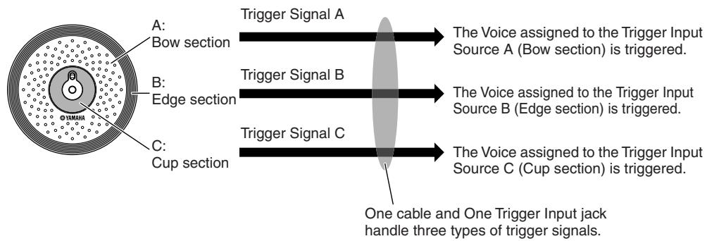
Example:PCY155
NOTE
- The KICK jack is a mono jack and cannot handle multiple trigger signals even when a 2-zone pad or 3-zone pad is connected.
- Pad Controllers generating different types of trigger signals according to the settings
Different types of Trigger Signal are generated also by using the Pad Controller of a drum pad. When a 3-zone snare drum pad (e.g., XP120SD) equipped with a Pad Controller is connected to the SNARE jack and the Pad Controller Type parameter is set to "snares" in the display called up via [DRUM KIT] [F5] PAD [SF1] PADCTRL, the XP120SD can generate two different types of trigger signals according to the snappy setting's on/off status controlled by the Pad Controller. By combining these two types with the three types generated depending on the particular zone you hit, a total of six different types of trigger signals can be generated from the XP120SD. For details, see below.
Six types of trigger signals generated by using a 3-zone pad and turning the Snappy setting On/Off
Example: XP120SD
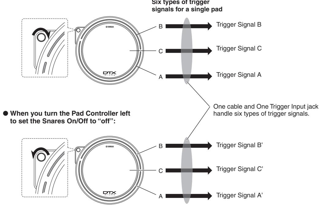
- When you turn the Pad Controller right to set the Snares On/Off to "on":
Hi-Hat Controllers generating different types of trigger signals according to the pressure applied
Hi-Hat cymbal pads (e.g., RHH135, 2-zone pad) can generate various types of trigger signal according to how deeply you press the Hi-Hat Controller (e.g., HH65 connected to the RHH135) as well as the two different types of signals generated depending where on the pad you hit.
Obtaining trigger signals from an acoustic drum
You can get trigger signals from an acoustic drum or similar percussion instrument by installing an appropriate drum trigger product (e.g., DT10 or DT20). This lets you trigger sounds on the DTX900 by playing the acoustic drum or percussion imt.
Trigger Setup
The DTX900 provides Trigger Setup parameters for optimum handling of the trigger signals transmitted from the pads and to ensure the expected sounds are produced. The Trigger Setup parameters include sensitivity (determining how the DTX900 responds to the trigger signal) and settings for avoiding problems such as double-triggering (two sounds played at the same time) and cross-talk (mixed input signals between the jacks).
The DTX900 lets you create up to five original settings as User Trigger Settings as well as the nine preset Trigger Settings.
Pad and Trigger Input Jack
As described above, some pads feature multiple Trigger Input Sources, each of which can generate its own trigger signal. Depending on the jack to which the pad is connected, however, some trigger signals cannot be transmitted to the DTX900. To avoid trigger signal drop outs, refer to the list below when connecting pads to the jacks on the rear panel of the DTX900.
| Pads | Trigger Input jacks of the DTX900 | |||||
| Model | Product name | (1) SNARE (2) TOM1 (3) TOM2 (4) TOM3 (5) TOM4 Compatible with 2-zone/3-zone pads and Pad Controllers | (6) RIDE (7) CRASH 1 (8) CRASH 2 Compatible with 2-zone/3-zone pads, but not compatible with Pad Controllers | (9) HI-HAT Compatible with 2-zone/3-zone pads, but not compatible with Pad Controllers | (10) KICK/(11) Not compatible with 2-zone/3-zone pads | (12) (13) (14) (15) Compatible with 2-zone/3-zone pads, but not compatible with Pad Controllers |
| XP100T | Tom pad | ◎ | (◎) | (◎) | (△) | ◎ |
| XP120T | Tom pad | ◎ | (◎) | (◎) | (△) | ◎ |
| XP100SD | Snare pad | ◎ | (◎) | (◎) | (△) | ◎ |
| XP120SD | Snare pad | ◎ | (◎) | (◎) | (△) | ◎ |
| TP65 | Tom pad | △ | (△) | (△) | (△) | △ |
| TP65S | Tom pad | ◎ | (◎) | ◎ | (△) | ◎ |
| TP100 | Tom pad | ◎ | (◎) | (◎) | (△) | ◎ |
| TP120SD | Snare pad | ◎ | (◎) | (◎) | (△) | ◎ |
| RHH130 | Hi-Hat pad | (○) | (○) | ○ | (△) | (○) |
| RHH135 | Hi-Hat pad | (○) | (○) | ○ | (△) | (○) |
| PCY65 | Cymbal pad | (△) | △ | (△) | (△) | △ |
| PCY65S | Cymbal pad | (○) | ○ | (○) | (△) | ○ |
| PCY130 | Cymbal pad | (△) | △ | (△) | (△) | △ |
| PCY130S | Cymbal pad | (○) | ○ | (○) | (△) | ○ |
| PCY130SC | Cymbal pad | (◎) | ◎ | (◎) | (△) | ◎ |
| PCY135 | Cymbal pad | (◎) | ◎ | (◎) | (△) | ◎ |
| PCY150S | Cymbal pad | (◎) | ◎ | (◎) | (△) | ◎ |
| PCY155 | Cymbal pad | (◎) | ◎ | (◎) | (△) | ◎ |
| KP65 | Kick pad | (△) | (△) | (△) | △ | (△) |
| KP125 | Kick pad | (△) | (△) | (△) | △ | (△) |
| KP125W | Kick pad | (△) | (△) | (△) | △ | (△) |
| DT10 | Drum trigger | △ | △ | △ | △ | △ |
| DT20 | Drum trigger | △ | △ | △ | △ | △ |
Indicates the corresponding pad model is compatible with 3-zone pads. In case of the XP model and the TP model, three types (two rim sections and head section) of trigger signals are recognized. In case of the PCY model, three types (bow, edge and cup sections) of trigger signals are recognized.
Indicates the corresponding pad model is compatible with 2-zone pads. In case of the RHH model, two types (bow and edge sections) of trigger signals are recognized. In case of the PCY model, three types (bow and edge sections) of trigger signals are recognized.
Indicates the corresponding pad functions as a mono pad.
( ) Indicates the corresponding pad can be connected to the corresponding jack although the preset data such as Drum Kit and Drum Voice will not assume such a case.
Trigger Input Sources
An entire pad, the particular section you hit and how you play the pad as a source of the trigger signal are collectively referred to as a "Trigger Input Source." One Trigger Source generates one type of trigger signal. Depending on the model, up to six Trigger Input Sources are provided in one pad. You can assign a Drum Voice to each Trigger Input Source on the DTX900 by following the instructions on page 79. Refer to the following list when assigning a Drum Voice.
Trigger Input Source List
| Trigger Source | Trigger Input jack | How the Trigger Signal is generated | |
| LCD indication | Full spell | ||
| snareHd | Snare Head | (1) SNARE | Hitting the head section of the snare drum pad (e.g., XP120SD). |
| snareOp | Snare Open Rim | (1) SNARE | Hitting the open rim shot section of the snare drum pad (e.g., XP120SD). |
| snareCI | Snare Closed Rim | (1) SNARE | Hitting the closed rim shot section of the snare drum pad (e.g., XP120SD). |
| snrHdOff | Snare Head Off | (1) SNARE | Hitting the head section of the snare drum pad (e.g., XP120SD) when the snappy setting (SnaresOn/Off parameter) is turned off. |
| snrOpOff | Snare Open Rim Off | (1) SNARE | Hitting the open rim shot section of the snare drum pad (e.g., XP120SD) when the snappy setting (SnaresOn/Off parameter) is turned off. |
| snrClOff | Snare Closed Rim Off | (1) SNARE | Hitting the closed rim shot section of the snare drum pad (e.g., XP120SD) when the snappy setting (SnaresOn/Off parameter) is turned off. |
| tom1Hd | Tom 1 Head | (2) TOM1 | Hitting the head section of the tom pad (e.g., XP120T). |
| tom1Rm1 | Tom 1 Rim 1 | (2) TOM1 | Hitting the rim 1 section of the tom pad (e.g., XP120T). |
| tom1Rm2 | Tom 1 Rim 2 | (2) TOM1 | Hitting the rim 2 section of the tom pad (e.g., XP120T). |
| : | : | : | : |
| tom4Hd | Tom 4 Head | (5) TOM4 | Hitting the head section of the tom pad (e.g., XP120T). |
| tom4Rm1 | Tom 4 Rim 1 | (5) TOM4 | Hitting the rim 1 section of the tom pad (e.g., XP120T). |
| tom4Rm2 | Tom 4 Rim 2 | (5) TOM4 | Hitting the rim 2 section of the tom pad (e.g., XP120T). |
| rideBw | Ride Cymbal Bow | (6) RIDE | Hitting the bow section of the cymbal pad. |
| rideEg | Ride Cymbal Edge | (6) RIDE | Hitting the edge section of the cymbal pad. |
| rideCp | Ride Cymbal Cup | (6) RIDE | Hitting the cup section of the cymbal pad. |
| crash1Bw | Crash Cymbal 1 Bow | (7) CRASH1 | Hitting the bow section of the cymbal pad. |
| crash1Eg | Crash Cymbal 1 Edge | (7) CRASH1 | Hitting the edge section of the cymbal pad. |
| crash1Cp | Crash Cymbal 1 Cup | (7) CRASH1 | Hitting the cup section of the cymbal pad. |
| crash2Bw | Crash Cymbal 2 Bow | (8) CRASH2 | Hitting the bow section of the cymbal pad. |
| crash2Eg | Crash Cymbal 2 Edge | (8) CRASH2 | Hitting the edge section of the cymbal pad. |
| crash2Cp | Crash Cymbal 2 Cup | (8) CRASH2 | Hitting the cup section of the cymbal pad. |
| hhBwOp | Hi-Hat Cymbal Open | (9) HI-HAT | Hitting the bow section of the cymbal pad when it is not closed by the hi-hat controller. |
| hhEgOp | Hi-Hat Cymbal Edge Open | (9) HI-HAT | Hitting the edge section of the cymbal pad when it is not closed by the hi-hat controller. |
| hhBwCI | Hi-Hat Cymbal Close | (9) HI-HAT | Hitting the bow section of the cymbal pad when it is closed by the hi-hat controller. |
| hhEgCI | Hi-Hat Cymbal Edge Close | (9) HI-HAT | Hitting the edge section of the cymbal pad when it is closed by the hi-hat controller. |
| hhFtCI | Hi-Hat Cymbal Foot Close | (9) HI-HAT | Pressing and holding the hi-hat controller by your foot. |
| hhSplsh | Hi-Hat Cymbal Foot Splash | (9) HI-HAT | Pressing and immediately releasing the hi-hat controller. |
| kick | Kick | (10) KICK | Pressing the kick pad by your foot. |
| pad11 | Pad 11 | (11) PAD11 | Hitting the snare pad or tom pad. |
| pad12Hd | Pad 12 Head | (12) PAD12 | Hitting the head section of the tom pad (e.g., XP120T). |
| pad12Rm1 | Pad 12 Rim 1 | (12) PAD12 | Hitting the rim 1 section of the tom pad (e.g., XP120T). |
| pad12Rm2 | Pad 12 Rim 2 | (12) PAD12 | Hitting the rim 2 section of the tom pad (e.g., XP120T). |
| : | : | : | : |
| pad15Hd | Pad 15 Head | (12) PAD15 | Hitting the head section of the tom pad (e.g., XP120T). |
| pad15Rm1 | Pad 15 Rim 1 | (12) PAD15 | Hitting the rim 1 section of the tom pad (e.g., XP120T). |
| pad15Rm2 | Pad 15 Rim 2 | (12) PAD15 | Hitting the rim 2 section of the tom pad (e.g., XP120T). |
Tone Generator Block (Drum Kits and Drum Voices)
The tone generator block is the section of the DTX900 which plays the Drum Voice assigned to the Trigger Input Source which transmits the trigger signal. Assigning each of Drum Voices to each of the Trigger Input Sources makes up a Drum Kit. A total of 50 Preset Drum Kits are provided in the DTX900. Drum Kits can be edited or created as desired and then stored to up to 50 User Drum Kit locations in internal memory, or stored to a maximum 1584 External Drum Kits (16 Banks x 99 kits = 1584 kits) in an external USB storage device connected to the USB TO DEVICE connector.
The DTX900 is a comprehensive sound source in it own right just with the built-in Preset Drum Kits; however, you get even more out of the instrument by understanding the internal structure and creating your own original Drum Kits.
Drum Voices assigned to each of the Trigger Input Sources
You can create your own original Drum Kit by assigning the desired Drum Voice to each of the Trigger Input Sources coming from the pad. For instructions, see page 61.
Assigning a Drum Voice to each of the Trigger Input Sources
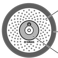
A:Assigning a Drum Voice to Trigger Input Source A.
B:Assigning a Drum Voice to Trigger Input Source B.
C:Assigning a Drum Voice to Trigger Input Source C.
Convenient Voice Set assignment for each Trigger Input jack
Assign Drum Voices to each of the Trigger Input Sources may be time-consuming and even tedious, difficult work. This is why the DTX900 provides the Voice Set parameter. Simply by selecting a value of the Voice Set parameter, you can assign the Drum Voices to all the Trigger Input Sources corresponding to the respective Trigger Input jacks. For instructions, see page 79.
Assigning a Voice Set to each of the Trigger Input jacks
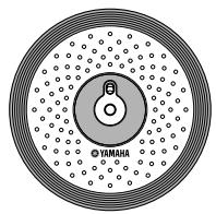
Assigning a Drum Voice to each of three Trigger Input Sources by assigning the Voice Set to the Trigger Input jack.
Drum Kits consisting of Voice Sets (Drum Voices)
For many players and composers, the Preset Drum Kits have all the sound variations you need. However, if you're looking for something different or want to customize the Kits, you change the sound by making Voice Set assignments for each of the Trigger Input jacks and create your original Drum Kit. If you want to go even further, you change the sound and create a Drum Kit by assigning Drum Voices to each of the Trigger Input Sources.
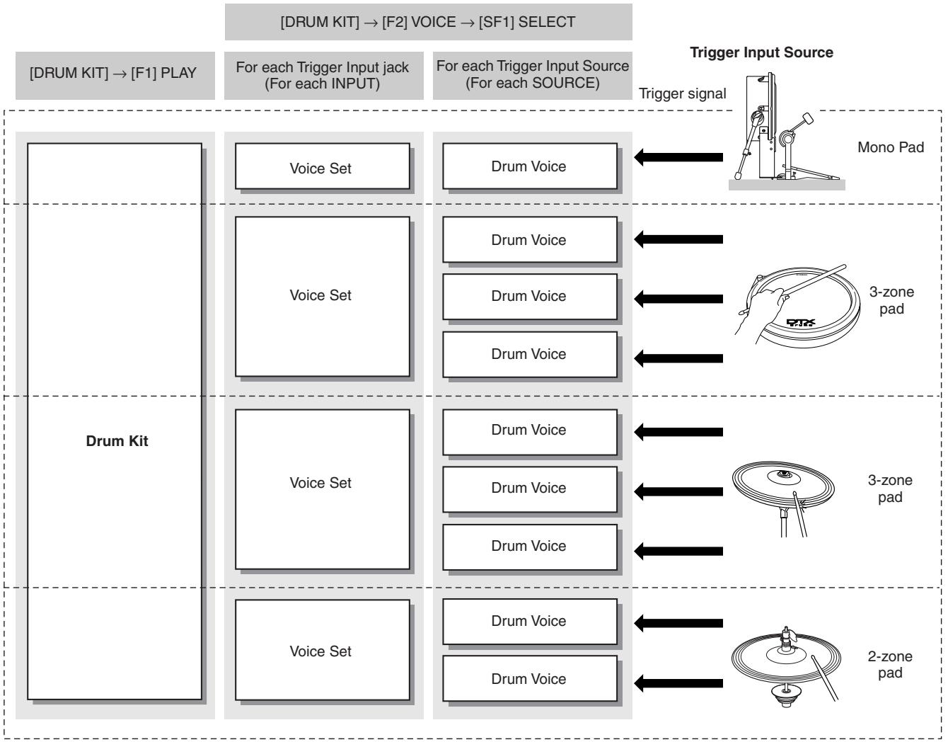
■ Drum Voices and MIDI note numbers
One important thing to understand is that separate Drum Voices are assigned to MIDI note numbers when using the Stack/Alternate function (page 86). While you may not need to pay attention to MIDI note numbers when using other functions, using the Stack/Alternate function requires that you set the MIDI note number instead of the Drum Voice.
For the currently selected Drum Kit, you can confirm which Drum Voice is assigned to each MIDI note number in the display called up by pressing the [DRUM KIT], [F2] VOICE, [SF1] SELECT buttons in order, setting the SOURCE to MIDI, then selecting a MIDI note number on the "NOTE NO" column. From this display, you can change the Drum Voice assigned to the MIDI note number, meaning that you can change the Drum Voice assigned to the Trigger Input Source (pad).
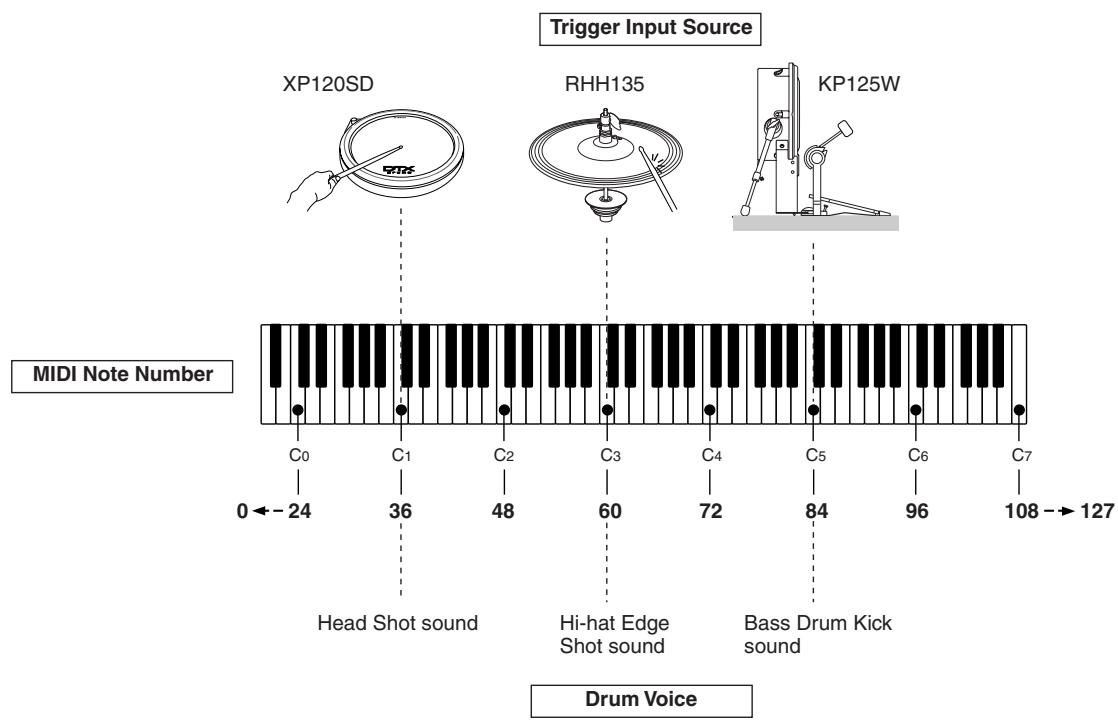
In the examples above, the Trigger Input Sources and Drum Voices listed below are assigned to the MIDI note numbers C1, C3 and C5 respectively.
| MIDI note number | Trigger Input Source | Drum Voice |
| C1 | Head section of the XP120SD | Head shot sound of the snare drum |
| C3 | Edge section of the RHH135 | Edge shot sound of the hi-hat cymbal |
| C5 | KP125W | Kick sound of the bass drum |
Sampling
The Sampling function lets you record audio signals such as vocals and CD playback sound to the DTX900 and play those sounds by hitting the drum pads. Recording audio signals to the DTX900 is referred to as "sampling." In addition to being able to record audio signals directly to the DTX900, you can also import existing audio data (in WAV or AIFF file format) in the File mode. This lets you use audio you've recorded and edited on computer with the DTX900. Once you've recorded or loaded the audio, you'll need to assign it to a User Voice which can be selected in the Drum Kit mode.
NOTICE
- The User Voices created in the Sampling mode reside temporarily in the optionally installed DIMMs (pages 76 and 147). Because data contained in DIMM is lost when the power is turned off, you should always save the User Voices created by recording, editing, and using Jobs to a USB storage device before turning off the power. For information on how to save, see pages 54 and 114.
IMPORTANT
In order to use the Sampling features of the instrument, you'll need to install DIMM memory modules (sold separately) to the instrument.
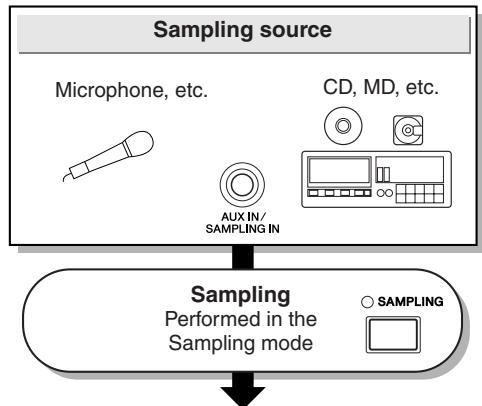
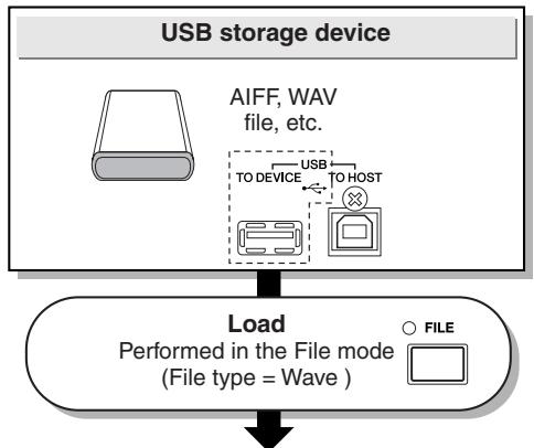
Destination to which the recorded audio signal is assigned
User Voice
Specified before the Sampling is started in the display called up via [SAMPLING] [F1] SELECT.
or
Specified before the Load is executed in the display called up via [FILE] [F2] LOAD.
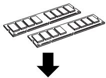
DIMM (sold separately)
Max. 512MB
Pad (Trigger Input Source)
Specified after Sampling is completed (Sampling mode).
or
Specified in the display called up via [DRUM KIT] [F2] VOICE [SF1] SELECT.
Save/Load
Performed in the File mode

USB storage device

File type
= AllData,AllVoice,
Wav, Aiff
Trigger mode
[ SAMPLING] [F6] REC Trigger Mode
The Trigger mode is a convenient feature in Sampling that lets you determine how recording is started—manually or automatically, based on the audio level.
- Starting recording manually
[ SAMPLING] [F6] REC Trigger Mode = manual
Regardless of the audio input signal level, sampling starts soon after you press the [F6] START button in the Sampling Standby display.
- Starting recording when the input signal exceeds the Trigger Level
[ SAMPLING] [F6] REC Trigger Mode = level
After pressing the [F6] START button in the Sampling Standby display, sampling starts as soon as a strong enough audio signal is received. The threshold for this audio-triggered start is called the Trigger Level (explained in the illustration below).
![YAMAHA DTX-900 - [ SAMPLING] [F6] REC Trigger Mode = level - 1](/content/2025/01/114986/images/a9e86aebd501f0b32f9feb65961e1db639c2ca04f1eed185c798a356195065a9.jpg)
![YAMAHA DTX-900 - [ SAMPLING] [F6] REC Trigger Mode = level - 2](/content/2025/01/114986/images/a15085e611bae79f707614ca810825b849123ff456dacedef21593d631118788.jpg)
As you can see, the higher the Trigger Level setting, the louder the input audio needs to be in order to start sampling. On the other hand, if the Trigger Level is set too low, a soft noise may be enough to inadvertently start sampling.
Song
A song consists of two sequence tracks (Tracks 1 and 2) and header data.
Each of two sequence tracks contains MIDI sequence data of 16 MIDI channels (channel 1 - 16). The DRUM, BASS and OTHER parts correspond to MIDI channels 10, 3, and the other channels respectively. These parts can be muted, regardless of which tracks they are on, by pressing the [SF1], [SF2] and [SF3] buttons.
The header data at the beginning of the song contains general song information such as Drum Kit number, tempo and time signature (BEAT), as well as program change and volume data for each MIDI channel. These types of data are automatically transmitted to the tone generator block when you select a song.
When song playback is started, this data is transmitted to the tone generator block for the sounds to be played back.
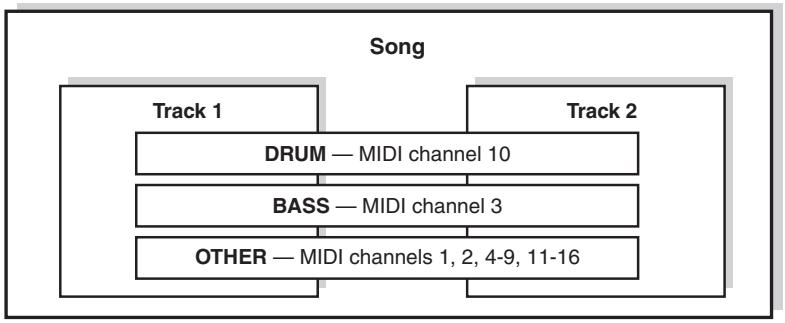
NOTE
- All the Preset Songs are recorded to the track 1.
NOTE
- Even if the [SF1] DRUM button is turned off, the drum part of only track 1 can be muted.
Playback of each Song can be started by hitting the specified pad as well as pressing the [▶/■] (Start/Stop) button. The function that lets you start/stop playback of a Song by hitting the specified pad is referred to as "Pad Song" (Page 93). Each Drum Kit can feature up to four Trigger Input Sources to which a Pad Song is assigned. Some Preset Drum Kits provide special Pad Song settings.
Since the DTX900 can play one main Song (normally started via the [ / ] button) and up to four Pad Songs at a time, you can play short phrases, such as a guitar riff or a chorded brass hit by hitting pads while playing the drum kit along with the main Song.
The Pad Song settings for each Drum Kit can be performed in the display called up via [DRUM KIT] [F5] PAD [SF3] PADSONG.
Effects
This block applies effects to the output of the tone generator block, processing and enhancing the sound using sophisticated DSP (digital signal processing) technology. Effects are applied in the final stages of editing, letting you change the sound as desired.
Effect Structure
The Effects of the DTX900 consist of the following blocks.
NOTE
- For detailed information about the Effect Types and related parameters, refer to pages 70 and 72 respectively. For a complete list of the available Effect Types for each Effect block, refer to the Effect Type List in the separate Data List booklet.
Reverb
The Reverb effects add a warm ambience to the sound, simulating the complex reflections of actual performance spaces, such as a concert hall or a small club. The Effect type of the Reverb block can be selected for each Drum Kit in the display called up via [DRUM KIT] [F4] EFFECT [SF1] CONNECT or [SF3] REVERB. The Effect of this block is applied to the overall sound of the DTX900.
Chorus
The Chorus effects use various types of modulation processing, including flanger and phaser, to enhance the sound in a variety of ways. The Effect type of the Chorus block can be selected for each Drum Kit in the display called up via [DRUM KIT] [F4] EFFECT [SF1] CONNECT or [SF4] CHORUS. The Effect of this block is applied to the overall sound of the DTX900.
Variation
The Effects of this block is applied only to the current Drum Kit sound. The Effect type of the Variation block can be selected for each Drum Kit in the display called up via [DRUM KIT] [F4] EFFECT [SF1] CONNECT or [SF2] VAR.
- Insertion A and Insertion B
The Effects of these two blocks is applied only to the audio signal coming from the external audio device or microphone. The Effect type for each of Insertion A and B can be selected in the display called up via [UTILITY] [F4] AUX IN [SF3] INS A and [SF4] INS B respectively.
Master Effect
This block applies effects to the final stereo output signal of the entire sound. The Master Effect type can be selected in the display called up via [UTILITY] [F3] EFFECT [SF2] MEF.
- Master EQ
Master EQ is applied to the final, overall (post-effect) sound of the instrument. The Master EQ can be set in the display called up via [UTILITY] [F3] EFFECT [SF1] MEQ.

Effect Connection
Effect Types and Effect Categories
The DTX900 provides such a wide and extensive variety of Effect types that it may be difficult to find the desired
Effect type out of the great number that are available. This is why all the Effect types are divided into convenient Effect categories.
This section explains the Effect categories and their types. The Effect Type list described below for each category contains the columns: REV (Reverb), CHO (Chorus), VAR (Variation), INS (Insertion) and MEF (Master Effect). The checkmarks indicated in these columns means the Effect Type is available for each block. These Effect types (with the checkmarks indicated in each list) can be selected from the panel controls.
COMPRESSOR & EQ
Compressor is an effect commonly used to limit and compress the dynamics (softness/loudness) of an audio signal. For signals that vary widely in dynamics, such as vocals and guitar parts, it "squeezes" the dynamic range, effectively making soft sounds louder and loud sounds softer. When used with gain to boost the overall level, this creates a more powerful, more consistently high-level sound. Compression can be used to increase sustain for electric guitar, smooth out the volume of a vocal, or bring a drum kit or rhythm pattern further up-front in the mix.
| Effect Type | VAR | INS | MEF | Description |
| COMPRES-SOR | ✓ | ✓ | ✓ | Vintage sounding compres-sion. |
| CLASSIC COMPRES-SOR | ✓ | ✓ | - | Conventional type of com-pressor. |
| MULTI BAND COMP | ✓ | ✓ | ✓ | 3-band type compressor. |
| EQ | ✓ | ✓ | - | Vintage 5-band parametric EQ. |
| HARMONIC ENHANCER | ✓ | ✓ | - | Adds new harmonics to the input signal to make the sound stand out. |
LO-FI
This effect intentionally degrades the audio quality of the input signal via several methods, including lowering of the sampling frequency.
| Effect Type | VAR | INS | MEF | Description |
| LO-FI | ✓ | ✓ | ✓ | Degrades the audio quality of the input signal for a lo-fi sound. |
| NOISY | ✓ | ✓ | - | Adds noise to the current sound. |
| DIGITAL TURNTABLE | ✓ | ✓ | - | Simulates the noise, scratches and pops of a vinyl record. |
FLANGER & PHASER
The flanger creates a swirling, metallic sound. The phaser modulates cyclically to add movement and animation to the sound.
| Effect Type | VAR | INS | CHO | Description |
| FLANGER | ✓ | ✓ | ✓ | Vintage sounding flanger. |
| CLASSIC FLANGER | ✓ | ✓ | ✓ | Conventional type of flanger. |
| TEMPO FLANGER | ✓ | ✓ | ✓ | Tempo-synchronized flanger. |
| DYNAMIC FLANGER | ✓ | ✓ | - | Dynamically controlled flanger. |
| PHASER MONO | ✓ | ✓ | ✓ | Vintage sounding mono phaser. |
| PHASER STEREO | ✓ | ✓ | ✓ | Vintage sounding stereo phaser. |
| TEMPO PHASER | ✓ | ✓ | ✓ | Tempo-synchronized phaser. |
| DYNAMIC PHASER | ✓ | ✓ | - | Dynamically controlled phase shifter. |
DISTORTION
This effect type is used mainly for guitar, adding distortion with an edge to the sound.
| Effect Type | VAR | INS | MEF | Description |
| AMP SIMULATOR 1 | ✓ | ✓ | - | Simulation of a guitar amp. |
| AMP SIMULATOR 2 | ✓ | ✓ | - | Simulation of a guitar amp. |
| COMP DISTORTION | ✓ | ✓ | - | Since compression is included in the first stage, steady distortion can be produced regardless of changes in input level. |
| COMP DISTORTION DELAY | ✓ | ✓ | ✓ | Compressor, Distortion and Delay effects are connected in series. |
WAH
This effect cyclically modulates the tone brightness (cutoff frequency of a filter). Auto Wah modulates the tone via LFO, Touch Wah modulates the tone via volume (note-on velocity) and Pedal Wah modulates the tone the pedal control.
| Effect Type | VAR | INS | Description |
| AUTO WAH | ✓ | ✓ | Modulates the tone via LFO. |
| TOUCH WAH | ✓ | ✓ | Modulates the tone via volume (note-on velocity). |
REVERB
Also called "reverberation," this refers to the sound energy remaining in a room or closed space after the original sound stops. Similar to yet different from echo, reverb is the indirect, diffuse sound of reflections from the walls and ceiling that accompany the direct sound. The characteristics of this indirect sound depends on the size of the room or space and the materials and furnishings in the room. Reverb Effect types use digital signal processing to simulate these characteristics.
| Effect Type | VAR | INS | REV | CHO | Description |
| REV-X HALL | - | - | ✓ | - | Reverb emulating the acoustics of a concert hall using REV-X technology. |
| R3 HALL | - | - | ✓ | - | Reverb emulating the acoustics of a concert hall using an algorithm derived from the Yamaha ProR3. |
| SPX HALL | ✓ | ✓ | ✓ | - | Reverb emulating the acoustics of a concert hall derived from the Yamaha SPX1000. |
| REV-X ROOM | - | - | ✓ | - | Reverb emulating the acoustics of a room using the REV-X technology. |
| R3 ROOM | - | - | ✓ | - | Reverb emulating the acoustics of a room using an algorithm derived from the Yamaha ProR3. |
| SPX ROOM | ✓ | ✓ | ✓ | - | Reverb emulating the acoustics of a room derived from the Yamaha SPX1000. |
| R3 PLATE | - | - | ✓ | - | Reverb emulating a metal plate using an algorithm derived from the Yamaha ProR3. |
| SPX STAGE | ✓ | ✓ | ✓ | - | Reverb designed for enhancing solo instruments, derived from the Yamaha SPX1000. |
| SPACE SIMULATOR | - | - | ✓ | - | Reverb which lets you set the space size by specifying the width, height, and depth. |
| EARLY REFLECTION | ✓ | ✓ | - | ✓ | This effect isolates only the early reflection components of the reverb. |
CHORUS
Depending on the particular chorus type and parameters, this can make a voice sound "larger," as if several identical instruments were playing in unison, or it can give a voice greater warmth and depth.
| Effect Type | VAR | INS | CHO | Description |
| G CHORUS | ✓ | ✓ | ✓ | This chorus effect produces a richer and more complex modulation than conventional chorus. |
| 2 MODULA-TOR | ✓ | ✓ | ✓ | This chorus effect consists of pitch modulation and amplitude modulation. |
| SPX CHORUS | ✓ | ✓ | ✓ | This effect uses a 3-phase LFO to add modulation and spaciousness to the sound. |
| SYMPHONIC | ✓ | ✓ | ✓ | A multi-stage version of SPX CHORUS modulation. |
| ENSEMBLE DETUNE | ✓ | ✓ | ✓ | Chorus effect without modulation, created by adding a slightly pitch-shifted sound. |
TREMOLO & ROTARY
The tremolo effect cyclically modulates the volume. The Rotary Speaker effect simulates the characteristic vibrato effect of a rotary speaker.
| Effect Type | VAR | INS | Description |
| AUTO PAN | ✓ | ✓ | Cyclically moves the sound left/right and front/back. |
| TREMOLO | ✓ | ✓ | Cyclically modulates the volume. |
| ROTARY SPEAKER | ✓ | ✓ | Simulation of a rotary speaker. |
DELAY
An effect (or device) that delays an audio signal for ambient or rhythmic effects.
| Effect Type | CHO | VAR | INS | MEF | Description |
| CROSS DELAY | ✓ | ✓ | ✓ | - | The feedback of the two delayed sounds is crossed. |
| TEMPO CROSS DELAY | ✓ | ✓ | ✓ | - | Cross delay synchronized with the tempo. |
| TEMPO DELAY MONO | ✓ | ✓ | ✓ | - | Mono delay synchronized with the tempo. |
| TEMPO DELAY STEREO | ✓ | ✓ | ✓ | - | Mono delay synchronized with the tempo. |
| CONTROL DELAY | - | ✓ | ✓ | - | Delay with delay time controllable in real time. |
| DELAY LR | ✓ | ✓ | ✓ | - | Produces two delayed sounds: L and R. |
| DELAY LCR | ✓ | ✓ | ✓ | - | Produces three delayed sounds: L, R and C (center). |
| DELAY LR (Stereo) | ✓ | ✓ | ✓ | ✓ | Produces two delayed sounds in stereo: L and R. |
TECH
This effect radically changes the tonal characteristics by using a filter and modulation.
| Effect Type | VAR | INS | MEF | Description |
| RING MODULATOR | ✓ | ✓ | ✓ | An effect that modifies the pitch by applying amplitude modulation to the frequency of the input. |
| DYNAMIC RING MODULATOR | ✓ | ✓ | - | Dynamically controlled ring modulation. |
| DYNAMIC FILTER | ✓ | ✓ | ✓ | Dynamically controlled filter. |
| AUTO SYNTH | ✓ | ✓ | - | Processes the input signal into a synthesizer-type sound. |
| ISOLATOR | ✓ | ✓ | ✓ | Controls the level of a speci-fied frequency band of the input signal. |
| SLICE | ✓ | ✓ | ✓ | Cuts the Voice sound into sep-arate segments for special rhythmic effects. |
| TECH MODU-LATION | ✓ | ✓ | - | Adds a unique feeling of mod-ulation similar to ring modula-tion. |
MISC
This category includes effect types not included in the other categories.
| Effect Type | VAR | INS | Description |
| TALKING MODULATOR | ✓ | ✓ | Adds a vowel sound to the input signal. |
| PITCH CHANGE | ✓ | ✓ | Changes the pitch of the input signal. |
REV-X
REV-X is a reverb algorithm developed by Yamaha. It provides high-density, richly reverberant sound quality, with smooth attenuation, spread and depth that work together to enhance the original sound. The DTX900 features two types of REV-X effects: REV-X Hall and REV-X Room.
Effect Parameters
Each of the Effect Types has parameters that determine how the Effect is applied to the sound. A variety of sounds can be obtained from a single effect type by setting these parameters. For information about the Effect parameters, see below.
■ Preset settings for Effect parameters
Preset settings for parameters of each effect type are provided as templates and can be selected in the Effect Type selection display. To get a desired effect sound, try first selecting one of the Presets close to your imagined sound, then change the parameters as necessary.
Effect parameters
NOTE
- Some parameters below may appear in different effect types with the same name, but actually have different functions depending on the particular effect type. For these parameters, two or three types of explanations are given.
| Paramatername | Descriptions |
| AEGPhs | Offsets the phase of the AEG. |
| AMDepth | Determines the depth of the amplitude modulation. |
| AMInvR | Determines the phase of the amplitude modulation for the R channel. |
| AmpType | Selects the amplifier type to be simulated. |
| AMSpeed | Determines the amplitude modulation speed. |
| AMWave | Determines the wave of the amplitude modulation. |
| Analog | Adds the characteristics of an analog flanger to the sound. |
| AtkOfst | Determines the amount of time that elapses between the hitting of a pad (or playing of a key) and the start of the wah effect. |
| AtkTime | Determines the attack time of the envelope follower. |
| Attack | Determines the amount of time that elapses between the hitting of a pad (or playing of a key) and the start of the compressor effect. |
| BitAsgn | Determines the degree to which the Word Length is applied to the sound, and affects the resolution of the sound. |
| Bottom*1 | Determines the minimum value of the wah filter. |
| ClickDensity | Determines the frequency at which the click sounds. |
| ClickLvl | Determines the click level. |
| Color*2 | Determines the fixed phase modulation. |
| CommonRel | This is one of the Multi Band Comp parameters and determines the amount of time that elapses between the releasing of a note and the end of the effect. |
| Compres | Determines the minimum input level at which the compressor effect is applied. |
| CtrType | This one of the Control Delay parameters. When set to “Normal,” the delay effect is always applied to the sound. When set to “Scratch,” the delay effect is not applied if both the Delay Time and Delay Time Offset are set to “0.” |
| Decay | Controls how the reverb sound decays. |
| Delay | [For TEMPO DELAY MONO, TEMPO DELAY STE-REO]Determines the delay of the sound in note value. This helps in setting rhythmic delays that match the timing of the music. [For TEC effects, CONTROL DELAY]Determines the delay time. |
| DelayC | Determines the delay time for the center channel. |
| DelayL | Determines the delay time for the L channel. |
| DelayL>R | Determines the amount of time between the moment the sound is input from the L channel and the moment the sound is output to the R channel. |
| DelayOfstR | Determines the delay time for the R channel as off-set. |
| DelayR | Determines the delay time for the R channel. |
| DelayR>L | Determines the amount of time between the moment the sound is input from the R channel and the moment the sound is output to the L channel. |
| Density | [For REVERB effects, except EARLY REFLECTION] Determines the density of the reverberations. [For EARLY REFLECTION] Determines the density of the reflections. |
| Depth | [For FLANGER] Determines the amplitude of the LFO wave which controls the cyclic change of the delay modulation. [For PHASER MONO, PHASER STEREO] Determines the amplitude of the LFO wave which controls the cyclic change of the phase modulation. [For SPACE SIMULATOR] Determines the depth of the simulated room. |
| Detune | Determines the amount of detuning of the pitch. |
| Device | Selects the device for changing how the sound is to be distorted. |
| Diffuse | [For TEMPO PHASER, EARLY REFLECTION] Determines the spread of the selected effect. [For REVERB effects, except EARLY REFLECTION] Determines the spread of the reverb. |
| Directn | Determines the direction of the modulation controlled by the envelope follower. |
| Div.Lvl | Determines the minimum level of the portions extracted via the slice effect. |
| DivFreqH | Determines the high frequency for dividing the entire sound into three bands. |
| DivFreqL | Determines the low frequency for dividing the entire sound into three bands. |
| DivideType | Determines how the sound (wave) is sliced by the note length. This helps in setting rhythmic effects that match the timing of the music. |
| DlyLvl | Determines the level of the delayed sound. |
| DlyLvIC | Determines the level of the delayed sound for the center channel. |
| DlyMix | Determines the mixing level of the delayed sound. |
| DlyOfst | Determines the offset value of the delay modulation. |
| DlyTrnsit | Determines the speed (rate) at which the delay time is changed from the current value to the specified new value. |
| Drive | [For HARMONIC ENHANCER, TALKING MODULA- TOR] Determines the extent to which the enhancer or talk- ing modulator is applied. [For NOISY, SLICE] Determines the degree and character of the distor- tion effect. |
| DriveHorn | Determines the depth of the modulation generated via the rotation of the horn. |
| DriveRotor | Determines the depth of the modulation generated via the rotation of the rotor. |
| Dry/Wet | Determines the balance of the dry sound and effect sound. |
| DryLPF | Determines the cutoff frequency of the low pass filter applied to the dry sound. |
| DryLvl | Determines the level of the dry sound (the unproc- essed sound). |
| DryMixLvl | Determines the level of the dry sound (the unproc- essed sound). |
| DrySndNoise | Determines the level of the dry signal sent to the noise effect. |
| Paramatername | Descriptions |
| DyLvIOfs | Determines the offset value added to the output from the envelope follower. |
| DyThreshLvl | Determines the minimum level at which the envelope follower starts. |
| Edge | Sets the curve that determines how the sound is distorted. |
| Emphasi | Determines the change of the characteristics in high frequencies. |
| EQ1Freq | Determines the Cutoff frequency of EQ1 (Low Shelving). |
| EQ1Gain | Determines the level gain of EQ 1 (Low Shelving). |
| EQ2Freq | Determines the center frequency of EQ2. |
| EQ2Gain | Determines the level gain of EQ2. |
| EQ2Q | Determines the Q of EQ2. |
| EQ3Freq | Determines the center frequency of EQ3. |
| EQ3Gain | Determines the level gain of EQ3. |
| EQ3Q | Determines the Q of EQ3. |
| EQ4Freq | Determines the center frequency of EQ4. |
| EQ4Gain | Determines the level gain of EQ4. |
| EQ4Q | Determines the Q of EQ4. |
| EQ5Freq | Determines the Cutoff frequency of EQ5 (High Shelving). |
| EQ5Gain | Determines the level gain of EQ5 (High Shelving). |
| EQFreq | Determines the center frequency for each band of the EQ. |
| EQGain | Determines the level gain of the EQ center frequency for each band. |
| EQWidth | Determines the width of the EQ band. |
| ER/Rev | Determines the level balance of the early reflection and reverb sound. |
| F/RDpth | This Auto Pan parameter (available when PAN Direction is set to “L turn” and “R turn”) determines the depth of the F/R (front/rear) pan. |
| FBHiDmp | Determines how the high frequencies of the feedback sound decay. |
| FBHiDmR | Determines the amount of decay in high frequencies for the R channel as offset. |
| FBLevel | [For CHORUS effects, DELAY effects, TECH effects, CLASSIC FLANGER, TEMPO FLANGER, DYNAMIC FLANGER, COMP DISTORTION DELAY] Determines the feedback level output from the delay and returned to the input. [For TEMPO PHASER, DYNAMIC PHASER] Determines the feedback level output from the delay and returned to the input. [For REVERB effects] Determines the feedback level of the initial delay. |
| FBLvl1 | Determines the feedback level of the delayed sound in the 1st series. |
| FBLvl2 | Determines the feedback level of the delayed sound in the 2nd series. |
| FBLvIR | Determines the feedback level for the R channel as offset. |
| FBTime | Determines the delay time of the feedback. |
| FBTime1 | Determines the delay time of feedback 1. |
| FBTime2 | Determines the delay time of feedback 2. |
| FBTimeL | Determines the delay time of the feedback for the left channel. |
| FBTimeR | Determines the delay time of the feedback for the right channel. |
| Feedback | Determines the level of the sound signal output from the effect block and returned to its own input. |
| Fine1 | Determines the fine pitch setting for the 1st series. |
| Fine2 | Determines the fine pitch setting for the 2nd series. |
| FltType | [For LO-FI] Determines the type of tonal characteristics. [For DYNAMIC FILTER] Determines the filter type. |
| GateTime | Determines the gate time of the sliced portion. |
| H.Freq | Determines the center frequency of the high EQ band that is attenuated/boosted. |
| H.Gain | Determines the amount of boost or attenuation applied to the high EQ band. |
| Height | Determines the height of the simulated room. |
| HiAtk | Determines the amount of time from the moment a note is played to the moment the compressor is applied to the high frequencies. |
| HiGain | Determines the output gain for the high frequencies. |
| HiLvl | Determines the level of the high frequencies. |
| HiMute | Switches the mute status of the high frequencies. |
| HiRat | [For MULTI BAND COMP]Determines the ratio of the compressor for the high frequencies. |
| HiRat | [For REVERB effects]Adjusts the resonance of the high frequencies. |
| HiTh | Determines the minimum input level at which the effect is applied to the high frequencies. |
| HornF | Determines the speed of the horn when the slow/fast switch is set to "fast." |
| HornS | Determines the speed of the horn when the slow/fast switch is set to "slow." |
| HPF | Determines the Cutoff frequency of the High Pass Filter. |
| InitDly | Determines the amount of time that elapses between the direct, original sound and the initial reflections. |
| InitDly1 | Determines the delay time for the 1st series. |
| InitDly2 | Determines the delay time for the 2nd series. |
| InitDlyL | Determines the delay time of the left channel. |
| InitDlyR | Determines the delay time of the right channel. |
| InpLvl | Determines the input level. |
| InpMode | Selects mono or stereo configuration for the input sound. |
| InpSelect | Selects an input. |
| L.Freq | Determines the center frequency of the low EQ band that is attenuated/boosted. |
| L.Gain | Determines the amount of boost or attenuation applied to the low EQ band. |
| L/RDiffuse | Determines the spread of the sound. |
| L/Rdpth | Determines the depth of the L/R pan effect. |
| Lag | Determines the lagging time additionally applied to the delayed sound, and is specified via a note length. This helps in setting rhythmic effects that match the timing of the music. |
| LFODpth | [For CHORUS effects, RING MODULATOR, CLASSIC FLANGER, TEMPO FLANGER]Determines the depth of the modulation. [For TEMPO PHASER]Determines the depth of the phase modulation. |
| LFOPhDiff | Determines the L/R phase difference of the modulated wave. |
| LFOPhRst | Determines how the initial phase of the LFO is reset. |
| LFOSpeed | [For CHORUS effects, TREMOLO, RING MODULATOR, CLASSIC FLANGER, TEMPO FLANGER]Determines the frequency of the modulation. [For TEMPO PHASER]Determines the modulation speed via a note length. This helps in setting rhythmic effects that match the timing of the music. [For AUTO PAN]Determines the frequency of the Auto Pan. |
| LFOWave | [For CLASSIC FLANGER, RING MODULATOR]Selects the wave for modulation. [For AUTO WAH]Selects the wave, sine or square. [For AUTO PAN]Determines the panning curve. |
| Paramatername | Descriptions |
| Livenesss | Determines the decay characteristics of Early Reflection. |
| LowAtk | Determines the amount of time from the moment a note is pressed to the moment the compressor is applied to the low frequencies. |
| LowGain | Determines the output gain for the low frequencies. |
| LowLvl | Determines the output level for the low frequencies. |
| LowMute | Determines whether the low frequency band is off or on. |
| LowRat | [For MULTI BAND COMP] Determines the ratio of the compressor for the low frequencies. |
| LowRat | [For REVERB effects] Determines the ratio of the low frequencies. |
| LowTh | Determines the minimum input level at which the effect is applied to the low frequencies. |
| LPF | Determines the cutoff frequency of the low pass filter. |
| LPFResto | Determines the Resonance of the Low Pass Filter for the input sound. |
| M.Freq | Determines the center frequency of the middle EQ band that is attenuated/boosted. |
| M.Gain | Determines the amount of boost or attenuation applied to the middle EQ band. |
| M.Width | Determines the width of the middle EQ band. |
| Manual | [For FLANGER] Determines the offset value of the delay modulation. [For PHASER MONO, PHASER STEREO] Determines the offset value of the phase modulation. |
| MicAngl | Determines the L/R angle of the microphone. |
| MidAtk | Determines the amount of time from the moment a note is pressed to the moment the compressor is applied to the mid frequencies. |
| MidGain | Determines the output gain for the mid frequencies. |
| MidLvl | Determines the output level for the mid frequencies. |
| MidMute | Switches the mute status of the mid frequencies. |
| MidRat | Determines the ratio of the compressor for the mid frequencies. |
| MidTh | Determines the minimum input level at which the effect is applied for the mid frequencies. |
| Mix | Determines the volume of the effect sound. |
| MixLvl | Determines the level of the effect sound mixed to the dry sound. |
| ModDpth | Determines the depth of the modulation. |
| ModDptR | Determines the depth of the modulation for the right channel as offset. |
| Mode | Determines the phaser type, or more specifically, the factor for forming the phaser effect. |
| ModFB | Determines the feedback level to the modulation. |
| ModGain | Determines the gain of the modulation. |
| ModLPF | Determines the cutoff frequency of the low pass filter applied to the modulated sound. |
| ModLPFReso | Determines the resonance of the low pass filter for the modulated sound. |
| ModMix | Determines the mix balance of the modulated element. |
| ModPh | Determines the L/R phase difference of the modulated wave. |
| ModSpd | Determines the modulation speed. |
| ModWave | Selects the wave type for modulation. |
| MoveSpeed | Determines how long it takes to move the sound from the current status to the sound specified via the Vowel parameter. |
| NoiseQ | Determines the resonance of the low pass filter applied to the noise. |
| NoisLPF | Determines the cutoff frequency of the low pass filter applied to the noise. |
| NoisLvl | Determines the noise level. |
| NoisModDpt | Determines the depth of the noise modulation. |
| NoisModSpd | Determines the speed of the noise modulation. |
| NoisTon | Determines the characteristics of the noise. |
| On/Off | Turns the isolator on or off. |
| OSCFrqCors | Determines the frequency for modulating the input wave. |
| OSCFrqFine | Finely determines the frequency for modulating the input wave. |
| OutGain | Determines the level gain. |
| OutLvl | Determines the output level. |
| OutLvl1 | Determines the output level for the 1st series. |
| OutLvl2 | Determines the output level for the 2nd series. |
| Output | Determines the output level. |
| OverDr | Determines the degree and character of the distortion effect. |
| Pan1 | Determines the pan position for the 1st series. |
| Pan2 | Determines the pan position for the 2nd series. |
| PanAEGLvl | This parameter of the Slice effect determines the minimum level of the AEG applied to the panned sound. |
| PanAEGType | This parameter of the Slice effect determines the type of the AEG applied to the panned sound |
| PanDirectn | Determines the type of the Auto Pan. |
| PanDpth | Determines the depth of the pan effect. |
| PanType | Determines the pan type. |
| PhShiftOfst | Determines the offset value of the phase modulation. |
| Pitch1 | Determines the pitch in semitones for the 1st series. |
| Pitch2 | Determines the pitch in semitones for the 2nd series. |
| PMDepth | Determines the depth of the pitch modulation. |
| Pre-LPF | Determines the Cutoff frequency of the Low Pass Filter before the modulation. |
| PreLPFResto | Determines the Resonance of the Low Pass Filter for the input sound. |
| PreModHPF | Determines the Cutoff frequency of the High Pass Filter before the modulation. |
| Presenc | This guitar amp effect parameter controls the high frequencies. |
| Ratio | Determines the ratio of the compressor. |
| RelCurv | Determines the release curve of the envelope follder. |
| Release | Determines the amount of time that elapses between the release or end of a sound and the end of the compressor effect. |
| RelTime | Determines the release time of the envelope follower. |
| Reso | Determines the resonance of the filter. |
| Resofst | Determines the resonance as offset. |
| RevDly | Determines the delay time from the early reflections until the reverberations. |
| RevTime | Determines the reverb time. |
| RoomSize | Determines the room capacity. |
| Rotor/Horn | Determines the volume balance of the horn and rotor. |
| RotorF | Determines the speed of the rotor when the slow/fast switch is set to "fast." |
| RotorS | Determines the speed of the rotor when the slow/fast switch is set to "slow." |
| Sens | [For FLANGER&PHASER effects, TECH effects]Determines the sensitivity of the modulation applied to the input change. [For TOUCH WAH]Determines the sensitivity of the wah filter's change applied to the input change. |
| S-FTmHorn | Determines how long it takes for the rotation speed of the horn to change from the current speed (slow or fast) to another speed (fast or slow) when the rotation speed is switched. |
| Paramatername | Descriptions |
| S-FTmRotor | Determines how long it takes for the rotation speed of the rotor to change from the current speed (slow or fast) to the another speed (fast or slow) when the rotation speed is switched. |
| SplIFrqCtr | Controls the sampling frequency. |
| SpcType | Selects the type of space simulation. |
| Speaker | Selects the type of speaker simulation. |
| Speed | [For FLANGER]Determines the frequency of the LFO wave which controls the cyclic change of the delay modulation. [For PHASER MONO, PHASER STEREO]Determines the frequency of the LFO wave which controls the cyclic change of the phase modulation. [For AUTO WAH]Determines the speed of the LFO. |
| SpeedCtrl | Switches the rotary speed. |
| Spread | Determines the spread of the sound. |
| Stage | Determines the step number of the phase shifter. |
| Thresh | Determines the minimum input level at which the effect is applied. |
| Top*3 | Determines the maximum value of the wah filter. |
| Type | [For FLANGER]Determines the type of flanger. [For WAH effects]Determines the type of Wah. [For EARLY REFLECTION]Determines the type of the reflection sound. |
| Vowel | Selects a vowel type. |
| WallVary | Determines the wall status of the simulated room. Higher settings produces more diffuse reflections. |
| Width | Determines the width of the simulated room. |
| WordLen | Determines the resolution of the sound, or how “rough” the sound is. |
1 The Bottom parameter is available only when the value is less than that of the Top parameter.
2 The Color parameter may not be effective depending on the values of the Mode and Stage parameters.
*3 The Top parameter is available only when the value is more than that of the Bottom parameter.
Internal Memory and File Management
As you use the DTX900, you'll create many different kinds of data, including Drum Kits, Drum Voices, Songs and Chain programs. This section describes how to maintain the various types of data and use the memory devices/media for storing them.
Data Lost and Retained When Power is Turned Off
The chart below lists the data types you can create on the instrument and the internal memory locations to which they are stored, permanently or temporarily. Keep in mind that certain types of data are lost when you turn off the power and you should always prepare a USB storage device for use BEFORE you start creating or editing data.
| Data types | Internal memory types to which data is stored |
| Drum Kit | Flash ROM |
| Click settings | Flash ROM |
| Trigger Settings | Flash ROM |
| Utility settings | Flash ROM |
| Chain | Flash ROM |
| User Song | DRAM → Will be lost when turning the power off! |
| User Voice | DIMM → Will be lost when turning the power off! |
NOTICE
- Among the data types above, the User Song and User Voice data should be saved to a USB storage device connected to the USB TO DEVICE connector before turning the power off. Otherwise, the created data will be lost.
Internal Memory
Below are explanations of the basic terms used in the Memory Structure illustration on the next page.
- Flash ROM
ROM (Read Only Memory) is memory designed specifically for reading out data, and as such data cannot be written to it. Unlike conventional ROM, Flash ROM can be overwritten – allowing you to store your own original data. The contents of Flash ROM are maintained even when the power is turned off.
- DRAM
RAM (Random Access Memory) is memory designed specifically for data writing and data reading operations. There are two different kinds of RAM, depending on the condition for storing the data: SRAM (Static RAM) and DRAM (Dynamic RAM). The created data stored on DRAM is lost when the power is turned off. Because of this, you should always store any data residing in DRAM to the USB storage device before turning off the power.
DIMM (sold separately)
DIMM modules must be installed in order for using the Sampling function or for loading audio data (User Voice/WAV file/AIFF file) to the instrument. As with DRAM described above, the created data stored on DIMM is lost when the power is turned off. Because of this, you should always store any data residing in DIMM to the USB storage device before turning off the power.
User Memory
The internal memory to which all the data you have created can be stored, permanently or temporarily is referred to as "User Memory."
Among various types of data created on the DTX900, data stored on Flash ROM can be maintained even if you turn the power off. On the other hand, data on DRAM (User Song) and DIMM (User Voice) should be saved to the USB storage device before turning the power off because these types of data will be lost when you turn the power off.
Memory Structure
This diagram details the relationship among the functions of the DTX900 and the internal memory and USB storage device.
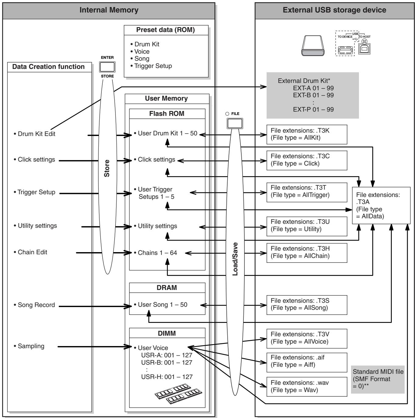
- External Drum Kits stored in the root directory of the USB storage device can be called up directly in the Drum Kit mode without the Load operation in the File mode. The file (Extension::T3E) will be created automatically when storing the drum kit to an external bank. Do not change the file name.
** Standard MIDI file Songs (format 0) saved in the root directory of the USB storage device can be called up directly in the Song mode and played back. This type of Songs can be loaded in the File mode with the File type "Song" as a User Song.
This chapter explains the Drum Kit mode called up via the [DRUM KIT] button.
In the Drum Kit mode, you can select and play the desired Drum Kit from 50 Preset Drum Kits (PRE: 01 to 50), with another 50 User Drum Kits (USR: 01 to 50) available for editing and creating your own kits. In addition, you can create and store original kits to the 1584 External Drum Kits (EXT-A: 01 - 99 ... EXT-P: 01 - 99) by using an external USB storage device connected to the USB TO DEVICE terminal. These Drum Kits can be called up directly, even though they are stored to an external device.
Basic Procedure in the Drum Kit Mode
Press the [DRUM KIT] button to enter the Drum Kit mode, then select a Drum Kit that most closely matches your desired settings.
2 Select the menu you wish to edit by pressing the [F1] - [F6] buttons.
When sub menus are assigned to the [SF1] - [SF6] buttons, select the desired sub menu for editing by pressing the [SF1] - [SF6] buttons.
When editing parameters in the [F2] VOICE, [F3] STK/ALT and [F5] PAD display, follow the procedure below.
2-1 From the [F2] VOICE display, press the [SF5] button to select "INPUT" or "SOURCE." When "INPUT" is selected, you can edit the parameters for each Trigger Input jack (pages 12 and 60). When "SOURCE" is selected, you can edit the parameters for each Trigger Source (page 61).
2-2 Select the Trigger Input jack or Trigger Input Source by hitting the corresponding pad or by using the [INC/YES], [DEC/NO] buttons and data dial with the cursor located on the INPUT or SOURCE position.
3 Move the cursor to the desired parameter by using the Cursor buttons, then set the value by using the [INC/YES], [DEC/NO] buttons and data dial.
4 Press the [ENTER/STORE] button after making the settings.
The following display appears.
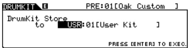
NOTE
- When a USB storage device is connected to the USB TO DEVICE terminal, you can store your original Drum Kit to the external ("EXT-A" - "EXT-P") banks as well as the internal User ("USR") bank.
5 Select the Drum Kit bank and number as destination by using the [INC/YES], [DEC/ NO] buttons and data dial.
6 Press the [ENTER/STORE] button.
The display prompts you for confirmation. To cancel the Store operation, press the [DEC/NO] button.
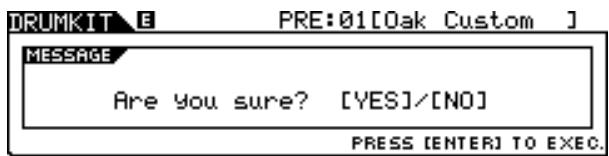
7 Press the [INC/YES] button to execute the Store operation.
NOTICE
- The edited Drum Kit will be lost when selecting a different Drum Kit or turning the power off. Make sure to store the Drum Kit data to internal memory by pressing the [ENTER/STORE] button before selecting a different Drum Kit or turning the power off.
- Never attempt to turn off the power while data is being written to Flash ROM (while a "Please keep power on" message is shown), otherwise all the User Drum Kit data on the instrument may be damaged or lost.
Selecting a Drum Kit
[F1] PLAY
Explanations about the display called up via the [DRUM KIT] [F1] PLAY are described on page 30 in the Quick Guide.
Setting Drum Voice Parameters
[F2] VOICE
Each of the displays called up via the [F2] button and [SF1] - [SF4] buttons provides two indication types: INPUT and SOURCE, which are shown at the top left of the display. From these displays, pressing the [SF5] button toggles the display type between "INPUT" (meaning that parameters can be edited for each Trigger Input jack) and "SOURCE" (meaning that parameters can be edited for each Trigger Input Source).
Assigning the Drum Voice to the Pad
[SF1] SELECT
When the INPUT display is called up, you can assign a Voice Set to each of the Trigger Input jacks. When the SOURCE display is called up, you can assign a Drum Voice to each of the Trigger Input Sources of the pad. By setting the SOURCE to MIDI on the SOURCE display, you can assign the Drum Voice to each MIDI note number. This is convenient when using the Stack/Alternate function (page 86).
NOTE
- For information about the relationship between Drum Kits, Drum Voices, Voice Sets, Trigger Input Sources and Trigger Input jacks, see page 62.
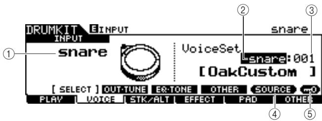
When the INPUT display is called up:
① INPUT
Determines the Trigger Input jack (to which the desired pad is connected). When Input Lock ⑤ is turned off, you can select the Trigger Input jack also by hitting the corresponding pad.
| Settings | snare, tom1, tom2, tom3, tom4, ride, crash1, crash2, hijat, kick, pad11, pad12, pad13, pad14, pad15 |
② Voice Set category
Determines the Voice Set category.
Settings kick, snare, tom, cymbal, hijat, perc, efct
NOTE
- In the INPUT display, an asterisk (*) will appear when the Voice set at each Trigger Input source is different from that in the current Voice Set.
③ Voice Set number
Determines the Voice Set number included in the Voice Set category selected at ②.
Settings Refer to the separate Data List booklet.
④ [SF5] SOURCE
Pressing the [SF5] button toggles the display type between "INPUT" (meaning that parameters can be edited for each Trigger Input jack) and "SOURCE" (meaning that parameters can be edited for each Trigger Input Source).
⑤ [SF6] Input Lock
You can turn the Input Lock on or off by pressing this button. When Input Lock is turned on (the [L] indicator appears at the top right of the display), the Trigger Input jack ① cannot be changed even if you hit any pad. This function is useful when you want to adjust the parameters of the current pad (connected to the current Trigger Input jack) while hitting other pads.
![YAMAHA DTX-900 - ⑤ [SF6] Input Lock - 1](/content/2025/01/114986/images/f584d2788241905a217dd8878e24d2d6a63c618ab913b9ab769193e905621237.jpg)
When the SOURCE display is called up:
① SOURCE
Determines the Trigger Input Source. When Input Lock (5) is turned off, you can select the Trigger Input Source also by hitting the corresponding section of the pad.
| Settings | Refer to the Trigger Input Source List on page 61. When “MIDI” is selected, you can assign the Drum Voice to each of the MIDI note numbers. |
② Voice category
Determines the Voice Category.
| Settings | kick1, kick2, snare1, snare2, snare3, tom1, tom2, cymbal, hihat, perc1, perc2, efct1, efct2, USR-A, USR-B, USR-C, USR-D, USR-E, USR-F, USR-G, USR-H |
③ Voice number
Determines the Voice number included in the Voice category selected at ②.
Settings Refer to the separate Data List booklet.
NOTE
- Check the Stack/Alternate settings; when "----" is displayed, you cannot select the voice category and number (page 86 and 126).
④ [SF5] INPUT
Pressing the [SF5] button toggles the display type between "INPUT" (meaning that parameters can be edited for each Trigger Input jack) and "SOURCE" (meaning that parameters can be edited for each Trigger Input Source).
⑤ [SF6] Input Lock
You can turn Input Lock on or off by pressing this button. When Input Lock is turned on (the [L] indicator appears at the top right of the display), the Trigger Input Source ① cannot be changed even if you hit any pad. This function is useful when you want to adjust the parameters of the current Trigger Input Source while hitting the pads of other Trigger Input Sources.
When "MIDI" is selected as SOURCE, the following display appears.
![YAMAHA DTX-900 - ⑤ [SF6] Input Lock - 1](/content/2025/01/114986/images/f0ddef956868023a17f49499c15cb66ded22d6aa628acf2f70ff07156a5dfeb3.jpg)
① Note number
Determines the MIDI note number to which you can assign the desired Drum Voice.
Settings C#1-A#5
NOTE
- MIDI note messages from an external MIDI device can also be used to set this parameter. Once this is set via MIDI, Input Lock can be used to disable further inadvertent editing.
Setting Volume, Tuning and Other Parameters
[SF2] OUT-TUNE
From this display, you can set parameters such as volume and tuning. This display consists of two pages, which can be called up via the Cursor [<] and [>] buttons.
The first page when the INPUT display is called up:
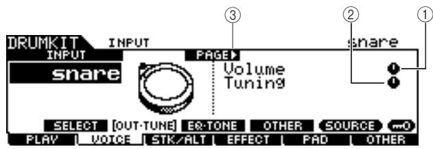
The first page when the SOURCE display is called up:
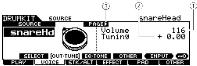
The initial page when the SOURCE display is called up and "MIDI" is selected:
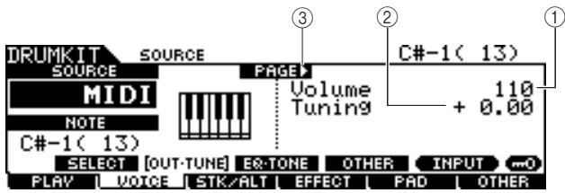
① Volume
When the INPUT display is called up, this parameter (for which the value is indicated in the knob icon) determines the volume of each selected Trigger Input Jack. When the SOURCE display is called up, this parameter determines the volume of each selected Trigger Input Source. You can adjust the volume balance among the Voices assigned to the pads by setting this parameter.
Range 0-127
② Tuning
When the INPUT display is called up, this parameter (for which the value is indicated in the knob icon) determines the pitch of each selected Trigger Input Jack. When the SOURCE display is called up, this parameter determines the pitch of each selected Trigger Input Source. The Tuning parameter can be adjusted finely in cents.
Range -24.00-+24.00
(3) PAGE
This appears when another page can be called up from the current page. Use the Cursor [>] or [<] button to call up another page.
The second page when the INPUT display is called up:
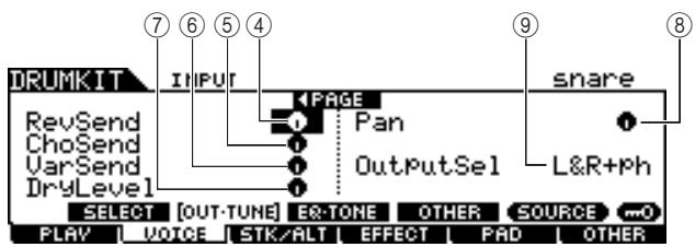
The second page when the SOURCE display is called up:
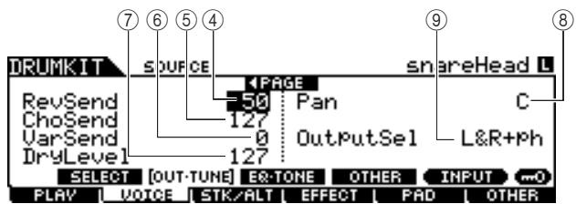
④ RevSend (Reverb Send)
When the INPUT display is called up, this parameter (for which the value is indicated in the knob icon) determines the Reverb Send level of each selected Trigger Input Jack. When the SOURCE display is called up, this parameter determines the Reverb Send level of each selected Trigger Input Source.
| Range | 0 – 127 |
⑤ ChoSend (Chorus Send)
When the INPUT display is called up, this parameter (for which the value is indicated in the knob icon) determines the Chorus Send level of each selected Trigger Input Jack. When the SOURCE display is called up, this parameter determines the Chorus Send level of each selected Trigger Input Source.
| Range | 0 – 127 |
⑥ VarSend (Variation Send)
When the INPUT display is called up, this parameter (for which the value is indicated in the knob icon) determines the Variation Send level of each selected Trigger Input Jack. When the SOURCE display is called up, this parameter determines the Variation Send level of each selected Trigger Input Source.
| Range | 0 – 127 |
⑦ Dry Level
When the INPUT display is called up, this parameter (for which the value is indicated in the knob icon) determines the unprocessed (dry) level of the Reverb/Chorus effects' signal for each selected Trigger Input Jack. When the SOURCE display is called up, this parameter determines the unprocessed (dry) level of the Reverb/Chorus effects' signal for each selected Trigger Input Source.
| Range | 0 – 127 |
⑧ Pan
When the INPUT display is called up, this parameter (for which the value is indicated in the knob icon) determines the pan (stereo) position of each selected Trigger Input Jack. When the SOURCE display is called up, this parameter determines the pan (stereo) position of each selected Trigger Input Source.
| Range | L63 – C – R63 |
⑨ OutputSel (Output Select)
When the INPUT display is called up, this parameter (for which the value is indicated in the knob icon) determines the Output jack of each selected Trigger Input Jack will be transmitted to the external device. When the SOURCE display is called up, this parameter determines the Output jack of each selected Trigger Input Source will be transmitted to the external device.
| Settings | L&R+ph (OUTPUT and PHONES), phones (PHONES), ind1&2 – ind5&6 (INDIVIDUAL OUTPUT 1 and 2 – 5 and 6), ind1 – ind6 (one of the INDIVIDUAL OUTPUTs), dryL&R (OUTPUT, Effect is not applied.) |
NOTE
- In the INPUT display, an asterisk (*) will appear when the value set at each Trigger Input source is different from this parameter.
Setting EQ- and Tone-related Parameters
[SF3] EQ-TONE
From this display, you can set the EQ related parameters and the Tone related parameters such as attack and release. This display consists of two pages, which can be called up via the Cursor [<] and [>] buttons.
The first page when the INPUT display is called up:
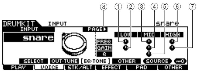
The first page when the SOURCE display is called up:
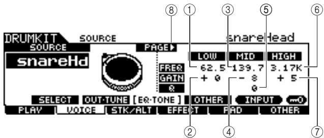
The first page when the SOURCE display is called up and "MIDI" is selected:
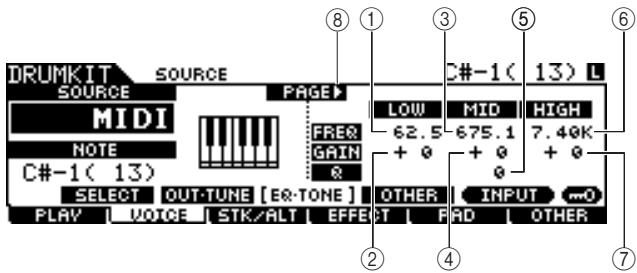
① Low Frequency
When the INPUT display is called up, this parameter (for which the value is indicated in the knob icon) determines the center frequency of the low EQ band that is attenuated/ boosted for each selected Trigger Input Jack. When the SOURCE display is called up, this parameter determines the center frequency of the low EQ band that is attenuated/ boosted for each selected Trigger Input Source.
Range 50.1-2.00k
② Low Gain
When the INPUT display is called up, this parameter (for which the value is indicated in the knob icon) determines the amount of boost or attenuation applied to the low EQ band for each selected Trigger Input Jack. When the SOURCE display is called up, this parameter determines the amount of boost or attenuation applied to the low EQ band for each selected Trigger Input Source.
Range -32-+32
③ Mid Frequency
When the INPUT display is called up, this parameter (for which the value is indicated in the knob icon) determines the center frequency of the middle EQ band that is attenuated/ boosted for each selected Trigger Input Jack. When the SOURCE display is called up, this parameter determines the center frequency of the middle EQ band that is attenuated/ boosted for each selected Trigger Input Source.
Range 139.7-10.1k
④ Mid Gain
When the INPUT display is called up, this parameter (for which the value is indicated in the knob icon) determines the amount of boost or attenuation applied to the middle EQ band for each selected Trigger Input Jack. When the SOURCE display is called up, this parameter determines the amount of boost or attenuation applied to the middle EQ band for each selected Trigger Input Source.
Range -32-+32
⑤ MIDQ
When the INPUT display is called up, this parameter (for which the value is indicated in the knob icon) determines the frequency bandwidth of the middle EQ band for each selected Trigger Input Jack. When the SOURCE display is called up, this parameter determines the frequency bandwidth of the middle EQ band for each selected Trigger Input Source.
Range 0-31
⑥ High Frequency
When the INPUT display is called up, this parameter (for which the value is indicated in the knob icon) determines the center frequency of the high EQ band that is attenuated/ boosted for each selected Trigger Input Jack. When the SOURCE display is called up, this parameter determines the center frequency of the high EQ band that is attenuated/ boosted for each selected Trigger Input Source.
Range 503.8 - 14.0k
⑦ High Gain
When the INPUT display is called up, this parameter (for which the value is indicated in the knob icon) determines the amount of boost or attenuation applied to the high EQ band for each selected Trigger Input Jack. When the SOURCE display is called up, this parameter determines the amount of boost or attenuation applied to the high EQ band for each selected Trigger Input Source.
Range -32-+32
(8) PAGE
This appears when another page can be called up from the current page. Use the Cursor [>] or [<] button to call up another page.
The second page when the INPUT display is called up:
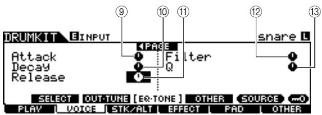
The second page when the SOURCE display is called up:
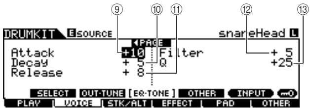
Attack
When the INPUT display is called up, this parameter (for which the value is indicated in the knob icon) determines the attack time (from the moment a pad is hit until the moment the maximum initial level of the volume is reached) of each selected Trigger Input Jack. When the SOURCE display is called up, this parameter determines the attack time of each selected Trigger Input Source.
Range -64- +63
10 Decay
When the INPUT display is called up, this parameter (for which the value is indicated in the knob icon) determines the decay time (indicating how fast the volume falls from maximum attack level) of each selected Trigger Input Jack. When the SOURCE display is called up, this parameter determines the decay time of each selected Trigger Input Source.
Range -64- +63
(1) Release
When the INPUT display is called up, this parameter (for which the value is indicated in the knob icon) determines the release time of each selected Trigger Input Jack. When the SOURCE display is called up, this parameter determines the release time of each selected Trigger Input Source.
Range -64-+63
NOTE
- This parameter is available only when the RcvKeyOff parameter is set to "on."
⑫ Filter
When the INPUT display is called up, this parameter (for which the value is indicated in the knob icon) determines the cutoff frequency of the low pass filter for each selected Trigger Input Jack. When the SOURCE display is called up, this parameter determines the cutoff frequency of the low pass filter for each selected Trigger Input Source.
Range -64-+63
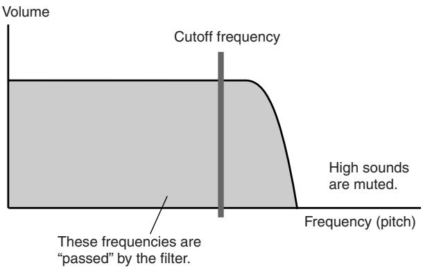
Low Pass Filter
13 Q (Resonance)
When the INPUT display is called up, this parameter (for which the value is indicated in the knob icon) determines the resonance of the low pass filter for each selected Trigger Input Jack. When the SOURCE display is called up, this parameter determines the resonance of the low pass filter for each selected Trigger Input Source. You can use this parameter to add further character to the sound or change the sound in more dramatic ways.
Range -64-+63
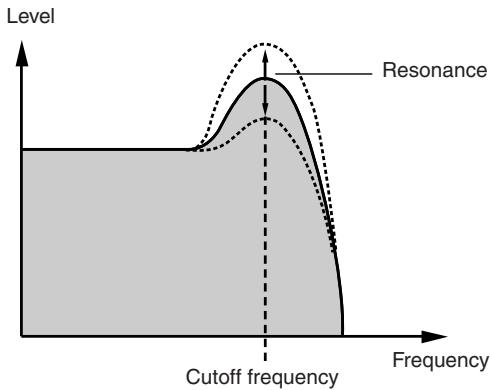
Setting Other Parameters
[SF4]OTHER
From this display, you can set parameters such as Mono/ Poly and Alternate Group. This display consists of two pages, which can be called up via the Cursor [<] and [>] buttons.
The first page when the INPUT display is called up:
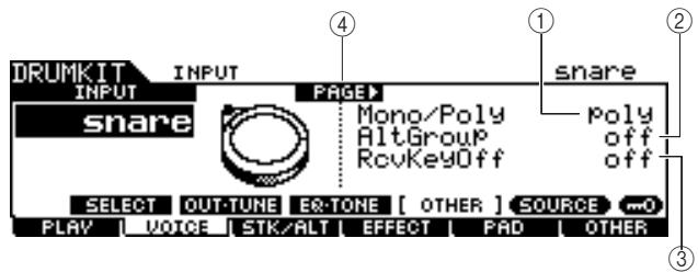
The first page when the SOURCE display is called up:
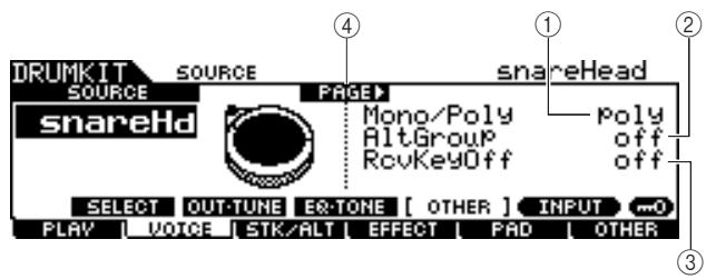
The first page when the SOURCE display is called up and "MIDI" is selected:
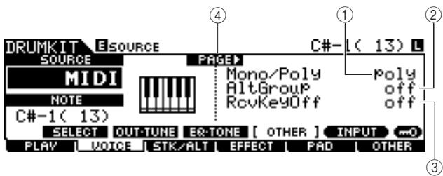
① Mono/Poly
When the INPUT display is called up, this parameter determines the playback of each selected Trigger Input Jack, mono or polyphonic. When the SOURCE display is called up, this parameter determines the playback of each selected Trigger Input Source, mono or polyphonic.
If "Mono" is selected, hitting the same pad repeatedly in succession will stop the sound generated by the previous hit, then start the same sound again. If "Poly" is selected, this limitation does not apply.
Settings
mono, poly
NOTE
- In the INPUT display, an asterisk (*) will appear when the value set at each Trigger Input source is different from this parameter.
② AltGroup (Alternate Group)
When the INPUT display is called up, this parameter determines the Alternate Group to which each selected Trigger Input Jack is assigned. When the SOURCE display is called up, this parameter determines the Alternate Group to which each selected Trigger Input Source is assigned.
In a real acoustic drum kit, some drum sounds cannot physically be played simultaneously, such as open and closed hithats. You can prevent Drum Voices from playing back simultaneously by assigning them to the same Alternate Group. Up to 127 Alternate Groups can be defined. You can also select "off" here if you wish to allow the simultaneous playback of sounds.
Settings
off,HHOpen,HHClose,1-124
NOTE
- Concerning the Drum Voices assigned to the same number (1 - 124) of the Alternate Group, only one of these Voices will be played back following the last-hitting priority. Concerning the Drum Voices assigned to the "HHOpen" and "HHClose," a special rule (below) is applied.
- Playing the Voice assigned to "HHOpen" will not stop the sound of the Voice assigned to "HHOpen" or "HHClose." Playing the Voice assigned "HHClose" will stop the sound of the Voice assigned to "HHOpen".
- In the INPUT display, an asterisk (*) will appear when the value set at each Trigger Input source is different from this parameter.
③ RcvKeyOff (Receive Key Off)
When the INPUT display is called up, this parameter determines whether or not each selected Trigger Input Jack responds to MIDI Note Off messages. When the SOURCE display is called up, this parameter determines whether or not each selected Trigger Input Source responds to MIDI Note Off messages.
This parameter is normally set to off since the sounds of many Drum Voices naturally decay and stop without the need for Note Off messages. This parameter should be set to on when the current Drum Voice has a sustained, non-decaying sound, so that you can stop the sound by sending MIDI note off messages to the internal tone generator. The timing the MIDI note off message is transmitted to the internal tone generator is determined by the Gate Time parameter in the STK/ALT display. You can also use the Hold Mode parameter to control MIDI Note Off messages (page 94).
Settings
off, on
NOTE
- In the INPUT display, an asterisk (*) will appear when the value set at each Trigger Input source is different from this parameter.
④ PAGE
This appears when another page can be called up from the current page. Use the Cursor [>] or [<] button to call up another page.
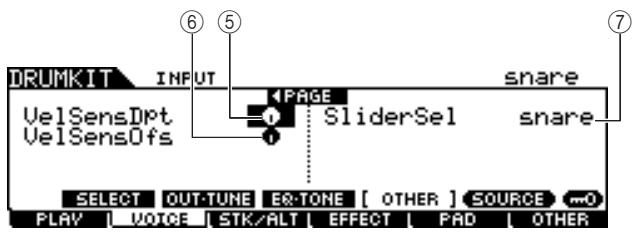
The second page when the INPUT display is called up:
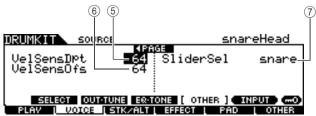
The second page when the SOURCE display is called up:
⑤ VelSensDpt (Velocity Sensitivity Depth)
When the INPUT display is called up, this parameter (for which the value is indicated in the knob icon) determines the degree to which the resulting volume of each selected Trigger Input Jack responds to the strength with which you hit the pad. When the SOURCE display is called up, this parameter determines the degree to which the resulting volume of each selected Trigger Input Source responds to the strength with which you hit the pad.
The higher the value, the more the volume changes in response to your hitting strength (as shown below).
Range
0-127
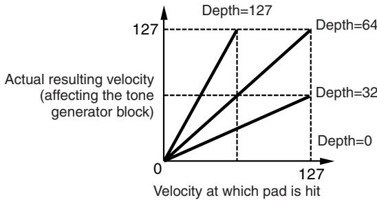
When the VelSensOfs parameter below is set to 64:
⑥ VelSensOfs (Velocity Sensitivity Offset)
When the INPUT display is called up, this parameter (for which the value is indicated in the knob icon) determines how the played velocities of each selected Trigger Input Jack affect the actual resulting velocity. When the SOURCE display is called up, this parameter determines how the played velocities of each selected Trigger Input Source affect the actual resulting velocity.
This lets you raise or lower all velocities by the same amount—allowing you to automatically compensate for playing too strongly or too softly. If the result is 0 or less, the value is set to 0. If the result is higher than 127, the value is set to 127.
| Range | 0 – 127 |
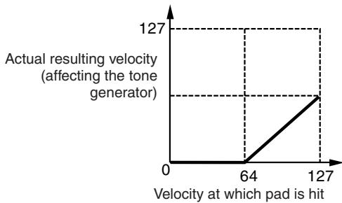
When Depth (above) = 64 and Offset = 32
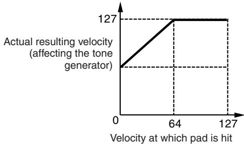
When Depth (above) = 64 and Offset = 96
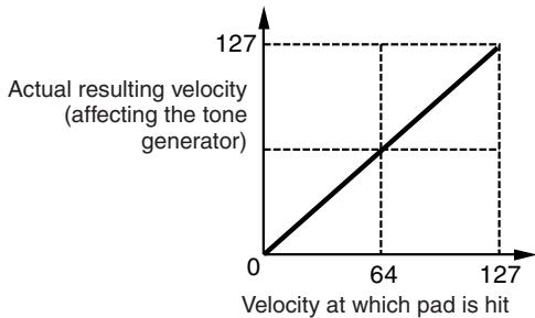
When Depth (above) = 64 and Offset = 64
⑦ SliderSel (Slider Select)
When the INPUT display is called up, this parameter determines the Slider with which you can adjust the volume of each selected Trigger Input Jack. When the SOURCE display is called up, this parameter determines the Slider with which you can adjust the volume of each selected Trigger Input Source.
| Settings | kick, snare, tom, cymbal, hihat, misc |
Programming the Stack/Alternate
[F3] STK/ALT
The Stack function lets you play several Drum Voices simultaneously by hitting only a single pad, while the Alternate function lets you play different Drum Voice(s) alternately.
In addition, the Stack function lets you play chords by using pitched Voices (called "Normal Voices" in Yamaha synthesizers) which can be called up by setting the CH (MIDI channel) to a number other than 10 (this channel is normally used by the DTX900 to play the Drum Voice) and assigning the Voice number to the corresponding channel in the display called up via [F6] OTHER [SF3] MIDI.
Note that the Stack/Alternate parameters can be set only for each Trigger Input Source.
NOTE
- In the internal tone generator of the DTX900, MIDI channel 10 is exclusively used for the Drum Voices. The MIDI messages generated by your drum performance will be transmitted to the internal tone generator over MIDI channel 10.
Programming the Stack/Alternate
When the cursor is located on the STEP column:
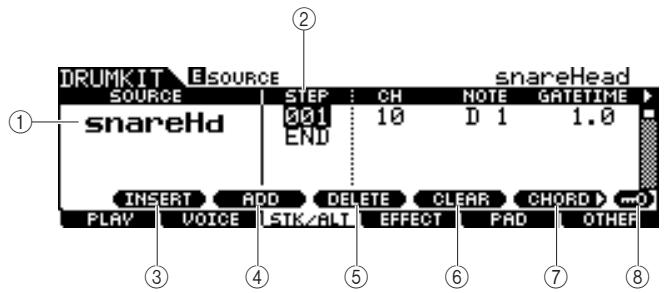
① SOURCE (Trigger Input Source)
Determines the Trigger Input Source which triggers the Stack/ Alternate function. You can change the Trigger Input Source by hitting the corresponding pad when Input Lock is turned off.
| Settings | Refer to page 61. |
(2) STEP
Determines the step number of the Alternate function. Only one Step 001 is preprogrammed in most preset Drum Kits., meaning that the Stack/Alternate function is not used. For example, each of the STEP "001" lines indicates the program when hitting the pad for the first time. Each of the STEP "002" lines indicates the program when hitting the pad for the second time. Likewise, the rest of the numbers such as "003" and "004" are the same as above.
When the number of the existing step is changed, the new step number's line blinks. Pressing the [ENTER/STORE] button to fix the step number and stop blinking.
Settings 001-100
③ [SF1] INSERT
Pressing this button inserts a new step at the current cursor location and increases the numbers of all the already-programmed steps after the cursor location by 1.
④ [SF2] ADD
Pressing this button adds a new step of the same number as that at the current cursor location without affecting the numbers of the other steps.
NOTE
- Up to 100 events for each Trigger Input Source (a total of 500 events for each Drum Kit) can be entered. An error message appears when you try to enter more steps than the limitation.
⑤ [SF3] DELETE
Pressing this button deletes the step at the current cursor location. If the step number is gone by deleting a certain step, the numbers of all the already-programmed steps after the cursor location are decreased by 1.
[SF4] CLEAR
Pressing this button clears the step at the current cursor location without affecting the numbers of the other steps.
⑦ [SF5] CHORD
Pressing this button calls up the different display used when you enter the Stack program by playing the external MIDI keyboard connected to the MIDI IN connector. For details, see page 87.
[SF6] Input Lock
You can turn Input Lock on or off by pressing this button. When Input Lock is turned on (the [L] indicator appears at the top right of the display), the Trigger Input jack ① cannot be changed even if you hit any pad. This function is useful when you want to adjust the parameters of the current pad (connected to the current Trigger Input jack) while hitting other pads.
The first page when the cursor is not located on the STEP column:
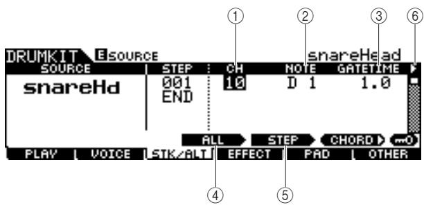
① CH (MIDI channel)
Determines the MIDI channel. With the default initial settings, this parameter is set to 10, which is normally used for the Drum Voice. If you want to play a pitched Voice, set this parameter to a number other than 10.
Settings 1-16
NOTE
- You can assign the Voice to each of the MIDI channels 1 - 16 on the display called up via the [DRUM KIT] [F6] OTHER [SF3] MIDI. This setting can be performed for each of the Drum Kits.
② NOTE
Determines the MIDI note number of the corresponding step.
Settings off, C#-2 - G8
NOTE
- For details about the relationship between the Drum Voices and MIDI note numbers, see page 62.
③ GATETIME
Determines the gate time (length from the moment you hit the pad to the moment the corresponding note off is transmitted to the tone generator block). In effect, this determines how long the resulting sound lasts.
Range 0.0s-9.9s
(4) [SF3] ALL
Regarding the CH, NOTE, GATE TIME and VELOCITY LIMIT parameters, you can change the current values of all the steps by simultaneously holding this button and using the data dial, [INC/DEC] and [DEC/NO] buttons.
⑤ [SF4] STEP
Regarding the CH, NOTE, GATE TIME and VELOCITY LIMIT parameters, you can change the current values of the current step number by simultaneously holding this button and using the data dial, [INC/DEC] and [DEC/NO] buttons.
(6) (page)
This appears when another page can be called up from the current page. Use the Cursor [>] or [<] button to call up another page.
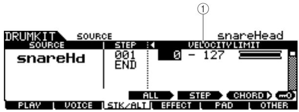
The second page:
① VELOCITY LIMIT
Determines the minimum and maximum values of the velocity range within which the Drum Voice will sound. The Drum Voice will sound only when you hit the pad at velocities within the range specified here.
| Range | 0 – 127 |
Example Stack/Alternate program
Here is an example of how you can use Stack/Alternate. In this example, hitting the pad once produces a C major chord. Hitting it a second time produces a G major chord, and a third hit produces a C major chord again.
Example program of the Stack/Alternate
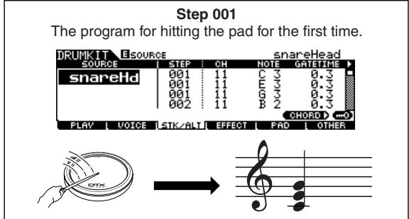
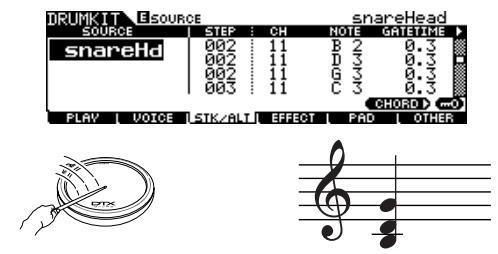
Step 002 The program for hitting the pad for the second time.
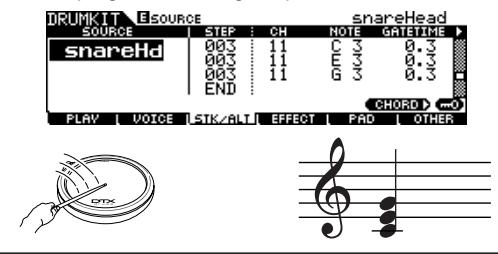
Step 003 The program for hitting the pad for the third time.
To create the above program, follow the procedure below.
Press the [F6] OTHER button followed by the [SF3] MIDI button to call up the MIDI display, allowing you to set the tone generator settings for each of the MIDI 16 channels.
2 Move the cursor to channel 11.
3 Move the cursor down to the TRANSMIT row, then set the TRANSMIT parameter of channel 11 to "All" or "PC."
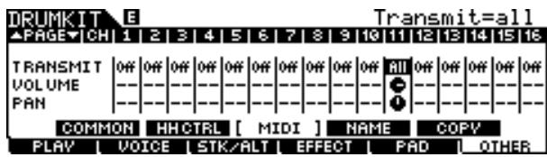
4 Move the cursor down again and set the VCE NUM, BANK MSB and BANK LSB, which determine the Voice program number.
For a complete list of available Voices, refer to the Data List booklet.

5 Call up the Stack/Alternate display again by pressing the [F3] STK/ALT button.
6 Create the program as illustrated above.
Enter the appropriate values shown in the Example Program illustration at the top of this section, using the [INC/YES], [DEC/NO] buttons and data dial. (You can also enter the notes directly from a MIDI keyboard; see "Programming the Stack from an external MIDI keyboard" below.)
7 Try out the newly created Stack/Alternate program by hitting the pad as many times as the step number.
Store the settings as a User Drum Kit by pressing the [ENTER/STORE] button.
Programming the Stack From an External MIDI Keyboard
[SF5] CHORD
You can enter note events from an external MIDI keyboard connected to the MIDI IN connector of the DTX900. This conveniently lets you play the chords and notes and directly enter them to the Stack program.
1 Connect one end of the MIDI cable to the MIDI OUT connector of the MIDI keyboard and the other to the MIDI IN connector of the DTX900.
2 On the MIDI keyboard, make the appropriate settings so that the MIDI connector is active.
If the MIDI keyboard is equipped with a USB TO HOST terminal, you may need to manually enable MIDI operation, depending on the MIDI parameter settings of your keyboard. For details, refer to the Owner's Manual of the MIDI keyboard.
3 On the DTX900, set the MIDI IN/OUT parameter to enable MIDI operation.
From the display called up via the [UTILITY] [F5] MIDI [SF3]OTHER, set the MIDI IN/OUT parameter to MIDI.
4 Call up the Stack/Alternate display again by pressing the [F3] STK/ALT button.
Press the [SF5] CHORD button to call up the Chord display.
This display is used for receiving MIDI note events from an external MIDI device and applying them to the current Stack/Alternate program.
6 Set the Step number by using the data dial, [INC/DEC] and [DEC/NO] buttons.
7 Play the MIDI keyboard.
The notes you play on the MIDI keyboard (along with the corresponding MIDI channel) appear in the display.
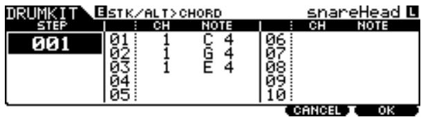
8 Press the [F6] OK button to actually apply the received notes to the current Stack/ Alternate program.
If you do not want to apply the received notes to the program, press the [F5] CANCEL button to go back to the original display.
9 Repeat steps 6 - 8 as desired.
10 Store the settings as a User Drum Kit by pressing the [ENTER/STORE] button.
Effect Settings
[F4] EFFECT
From the displays called up via the [F4] EFFECT button, you can set the Effect related parameters for the current Drum Kit. In the Drum Kit mode, you can set the parameters of the Reverb effects, Chorus effects and Variation Effects. The Reverb and Chorus effects are applied to the entire DTX900 sound as well as the Drum Kit sound while the Variation effects are applied only to the Drum Kit sound. For details about the Effect structure, see page 68.
Effect Connection Settings
[SF1] CONNECT
This display gives you at-a-glance, overall view of the effect routing and comprehensive control over the effects.
![YAMAHA DTX-900 - [SF1] CONNECT - 1](/content/2025/01/114986/images/922eab78f7c095b36203f91faf136d23759f4c2e8bbd0e21f353dadeeeb50e6a.jpg)
① Variation Effect Category
Determines the Variation Effect Category.
| Settings | Details about the Effect categories and types are described on page 70. |
(2) Variation Effect Type
Determines the Variation Effect Type.
| Settings | Details about the Effect categories and types are described on page 70. |
③ Chorus Effect Category
Determines the Chorus Effect Category.
| Settings | Details about the Effect categories and types are described on page 70. |
④ Chorus Effect Type
Determines the Chorus Effect Type.
| Settings | Details about the Effect categories and types are described on page 70. |
⑤ Reverb Effect Type
Determines the Reverb Effect Type. You need not select the Reverb Effect Category because the effect types of the Reverb block are not divided into multiple categories.
| Settings | Details about the Effect categories and types are described on page 70. |
(6) Variation Return
Determines the Return level of the Variation Effect.
| Range | 0 – 127 |
[F4] EFFECT
(7) Variation To Chorus
Determines the Send level of the signal sent from the Variation Effect to the Chorus Effect.
| Range | 0 – 127 |
(8) Variation To Reverb
Determines the Send level of the signal sent from the Variation Effect to the Reverb Effect.
| Range | 0 – 127 |
(9) Variation Pan
Determines the pan position of the Variation effect sound.
| Range | L63 (far left) – C (center) – R63 (far right) |
10 Chorus Return
Determines the Return level of the Chorus Effect.
| Range | 0 – 127 |
11 Chorus To Reverb
Determines the Send level of the signal sent from the Chorus Effect to the Reverb Effect.
| Range | 0 – 127 |
⑫ Chorus Pan
Determines the pan position of the Chorus effect sound.
| Range | L63 (far left) – C (center) – R63 (far right) |
13 Reverb Return
Determines the Return level of the Reverb Effect.
| Range | 0 – 127 |
14 Reverb Pan
Determines the pan position of the Reverb effect sound.
| Range | L63 (far left) – C (center) – R63 (far right) |
[SF5] BYPASS
Pressing this button toggles the bypass status of all three Effect blocks (Reverb, Chorus and Variation) between on and off.
When Bypass is turned off (the BYPASS indication is shown with white text in black), the Reverb, Chorus and Variation Effects are applied to the Drum Kit sound. When Bypass is turned on (the BYPASS indication is shown with black text in white), one or two or all three of the Effects will be bypassed for the Drum Kit sound. The box surrounding the bypassed Effect block (either of C: VAR, C: CHO, and REV) is indicated with a dotted line while the box surrounding the non-bypassed Effect block is indicated with a solid line.
Variation Effect Settings
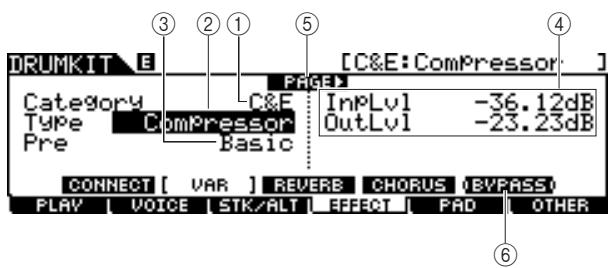
[SF2] VAR
① Category
② Type
Equivalent to ① and ② of the [SF1] CONNECT display. You can select the Variation Effect type from the Type column. If it is difficult to find the desired Effect type, select the Category first, then select the Type.
| Settings | Details about the Effect categories and types are described on page 70. |
③ Preset
You can set various parameters in order to change how the sound is affected by the selected Effect type. This parameter lets you call up the pre-programmed settings of these effect parameters.
| Settings | Refer to the separate Data List booklet. |
④ Effect Parameters
The number of parameters and values available differs depending on the currently selected effect type. Refer to page 72 for details about the Effect parameters. Refer to the separate Data List booklet for information on the parameters for each Effect type.
(5) PAGE
This appears when another page can be called up from the current page. Use the Cursor [>] or [<] button to call up another page.
⑥ [SF5] BYPASS
Pressing this button toggles the bypass status of the Variation Effect between on and off.
When Bypass is turned off (the BYPASS indication is shown with white text in black), the Variation Effect is applied to the Drum Kit sound. When Bypass is turned on (the BYPASS indication is shown with black text in white), the Variation Effect is not applied to the Drum Kit sound.
Reverb Effect Settings
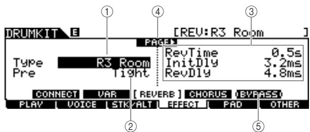
[SF3] REVERB
① Type
Equivalent to ⑤ of the [SF1] CONNECT display. You can select the Reverb Effect type from the Type column.
| Settings | Details about the Effect categories and types are described on page 70. |
② Preset
You can set various parameters in order to change how the sound is affected by the selected Effect type. This parameter lets you call up the pre-programmed settings of these effect parameters.
| Settings | Refer to the separate Data List booklet. |
③ Effect Parameters
The number of parameters and values available differs depending on the currently selected effect type. Refer to page 72 for details about the Effect parameters. Refer to the separate Data List booklet for information on the parameters for each Effect type.
④ PAGE
This appears when another page can be called up from the current page. Use the Cursor [>] or [<] button to call up another page.
⑤ [SF5] BYPASS
Pressing this button toggles the bypass status of the Reverb Effect between on and off.
When Bypass is turned off (the BYPASS indication is shown with white text in black), the Reverb Effect is applied to the Drum Kit sound. When Bypass is turned on (the BYPASS indication is shown with black text in white), the Reverb Effect is not applied to the Drum Kit sound.
Chorus Effect Settings
[SF4] CHORUS
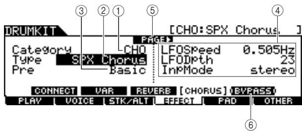
① Category
② Type
Equivalent to ③ and ④ of the [SF1] CONNECT display. You can select the Chorus Effect type from the Type column. If it is difficult to find the desired Effect type, select the Category first, then select the Type.
| Settings | Details about the Effect categories and types are described on page 70. |
③ Preset
You can set various parameters in order to change how the sound is affected by the selected Effect type. This parameter lets you call up the pre-programmed settings of these effect parameters.
| Settings | Refer to the separate Data List booklet. |
④ Effect Parameters
The number of parameters and values available differs depending on the currently selected effect type. Refer to page 72 for details about the Effect parameters. Refer to the separate Data List booklet for information on the parameters for each Effect type.
⑤ PAGE
This appears when another page can be called up from the current page. Use the Cursor [>] or [<] button to call up another page.
⑥ [SF5] BYPASS
Pressing this button toggles the bypass status of the Chorus Effect between on and off.
When Bypass is turned off (the BYPASS indication is shown with white text in black), the Chorus Effect is applied to the Drum Kit sound. When Bypass is turned on (the BYPASS indication is shown with black text in white), the Chorus Effect is not applied to the Drum Kit sound.
Pad Settings
[F5] PAD
Assigning a Function to the Pad Controller
[SF1] PADCTRL
From this display, you can assign a function to the Pad Controller with which the TP100 and XP120SD are equipped.
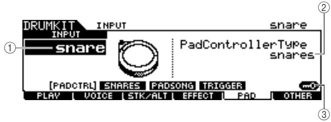
① INPUT (Trigger Input jack)
Determines the Trigger Input jack (equivalent to the connected pad) to be edited. Note that this parameter can be set only for each Trigger Input jack.
| Settings | snare, tom1, tom2, tom3, tom4, ride, crash1, crash2, hihat, kick, pad11, pad12, pad13, pad14, pad15 |
② Pad Controller Type
Determines the function assigned to the Pad Controller of the pad connected to the Trigger Input jack specified at ①.
| Settings | off, snares, tuning, tempo, filter, voice |
| off | No function is assigned to the Pad Controller. |
| snares | Turning the Pad Controller adjusts how strongly or softly the snappy parameter is "stretched," or adjusts the Snares On/Off and Snares Adjust parameters in the display called up via the [DRUM KIT] → [F5] PAD → [SF2] SNARES. Turning the Pad Controller to the left (counterclockwise) progressively loosens the snappy effect, and finally unlocks it. Turning the Pad Controller to the right (clockwise) tightens the snappy effect. If the snappy effect is unlocked, turn the Pad Controller to the right to lock it. |
| tuning | The Pad Controller adjusts the tuning of the Drum Voice, or adjusts the Tuning parameters in the display called up via the [DRUM KIT] → [F2] VOICE → [SF2] OUT-TUNE. Turning the Pad Controller to the left (counterclockwise) lowers the pitch. Turning the Pad Controller to the right (clockwise) raises the pitch. |
| tempo | The Pad Controller adjusts the tempo of the Song playback or Click sound. The LED display shows the tempo of the Song or Click sound while turning the Pad Controller. |
| filter | The Pad Controller adjusts the tonal characteristics of the Drum Voice, or adjusts the Filter parameter in the display called up via the [DRUM KIT] → [F2] VOICE → [SF3] EQ-TONE. Turning the Pad Controller to the left (counterclockwise) makes the Drum Voice sound more muffled or darker. Turning the Pad Controller to the right (clockwise) makes the Drum Voice sound brighter. |
voice
Turning the Pad Controller sets the snappy on/off status or sets the Snares On/Off parameters in the display called up via the [DRUM KIT] [F5] PAD [SF2] SNARES.
Turning the Pad Controller to the left (counterclockwise) unlocks the snappy effect, or sets the Snares On/Off parameters to off. Turning the Pad Controller to the right (clockwise) locks the snappy effect, or sets the Snares On/Off parameters to on.
NOTE
- The initial default setting of the Pad Controller Type differs depending on the Drum Kit.
- The available value above differs depending on the selected Trigger Input jack. For example, "snares" and "voice" are available only when the INPUT (Trigger Input jack) is set to "snare."
③ [SF6] Input Lock
You can turn the Input Lock on or off by pressing this button. When the Input Lock is turned on (the [L] indicator appears at the top right of the display), the Trigger Input jack ① cannot be changed even if you hit any pad. This function is useful when you want to adjust the parameters of the current pad (connected to the current Trigger Input jack) while hitting other pads.
Snappy Settings
[SF2] SNARES
From this display, you can set the parameters related to the snappy effect of the snare drum pad connected to the SNARE jack. These parameters can be changed also from the Pad Controller of the drum pad connected to the SNARE jack.
Keep in mind that the settings in this display are available only for the drum pad connected to the SNARE jack.
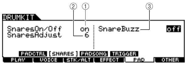
(1) Snares On/Off
Determines the snappy effect's status. When set to on, the snappy effect is locked. When set to off, it is unlocked.
| Settings | off, on |
② Snares Adjust
Determines the degree to which the snappy effect is "stretched." Setting this to "1" makes the snappy effect most loose. The higher the value, the tighter the stretching is.
| Range | 1 – 24 |
NOTE
- Setting this parameter changes the Decay parameter of "snareHd" and "snareOp" in the display called up via the [DRUM KIT] [F2] VOICE [SF3] EQ-TONE.
③ Snare Buzz
Determines whether or not the snappy effect resonates with the Kick or Tom sound. When set to on, the snappy effect resonates with the Kick or Tom sound.
| Settings | off, 1 – 5 |
Pad Song Settings
[SF3] PADSONG
From this display, you can set the parameters related to the Pad Song for each Trigger Input Source. The Pad Song function lets you play a Song by hitting the pad instead of pressing the [ / ] button. One Song is assigned to one Trigger Input Source and up to four Pad Songs can be set.
![YAMAHA DTX-900 - [SF3] PADSONG - 1](/content/2025/01/114986/images/d6f9274e455349b288971db6de6bd71fea4014562e1783158b940d263dd20eff.jpg)
① SOURCE (Trigger Input Source)
Determines the Trigger Input Source to which you want to assign the Pad Song. You can change the Trigger Input Source by hitting the corresponding pad when Input Lock is turned off.
| Settings | Refer to the Trigger Input Source List on page 61. |
② Pad Song
Determines whether or not the Pad Song is assigned to the selected Trigger Input Source. When set to on, the Trigger Input Source can be used to start playback of the Song specified below. When set to off, the rest of the parameters below cannot be set.
| Settings | off, on |
NOTE
- You can play up to four pad songs from one drum kit. If you have already specified four pad songs for other trigger input sources, the following parameter (3) - (5) cannot be set and “-” is shown in the display.
③ Song No (Song number)
Determines the Song number when the Pad Song is set to on. You can start playback of the Song specified here by hitting the pad corresponding to the Trigger Input Source. When the Pad Song is set to off, this parameter cannot be set.
| Settings | PRE: 01 - 87, USR: 01 - 50 |
④ Repeat
Determines whether or not the song plays back repeatedly. When set to on, the Song (started by hitting the pad) will play back repeatedly. When set to off, the Song playback will stop automatically when it reaches the end.
| Settings | off, on |
⑤ Mode
Determines how the Song playback responds to your pad hitting. When "play" is selected, hitting the pad starts or stops the specified Song. When "chase" is selected, hitting the pad plays only one measure of the specified Song. When "cutoff" is selected, hitting the pad stops any Songs started by hitting other pads (for which the Mode parameter is set to "cutoff") then starts the specified Song. Hitting the pad again stops the specified Song. Keep in mind that only a single Song can play back from all the Pad Songs for which the Mode parameter is set to "cutoff."
| Settings | play, chase, cutoff |
[6] [SF5] INFO (Information)
Pressing this button calls up the display which indicates the Pad Song settings.
![YAMAHA DTX-900 - [6] [SF5] INFO (Information) - 1](/content/2025/01/114986/images/3a1d52a424e57acec860a60ed368116563b204bb0dd2231582d7c1c0c39208ab.jpg)
NOTE
- The Pad Song plays back according to the tempo specified in the Song mode or Click mode. The DTX900 has only the single tempo value.
- Keep in mind that hitting the pad softly may not start the Pad Song. Make sure to hit the pad more strongly than a specified level.
- If both the Pad Function (which can be set in the display called up via the [UTILITY] [F2] PAD [SF2] PADFUNC) and Pad Song are assigned to the Trigger Input Source, the Pad Song setting is canceled.
- Depending on the selected Pad Songs and normal Song, an unexpected sound may be produced. This is because each Song may be transmitting different setups to the internal tone generator via the same MIDI channel. If you plan on using two or more Songs together, you should make sure that the MIDI channels used for the Songs are all set to different values.
Trigger Signal Settings
[SF4]TRIGGER
From this display, you can set the parameters which determine how the DTX900 responds to the Trigger Signal for each Trigger Input Source. This display consists of two pages.
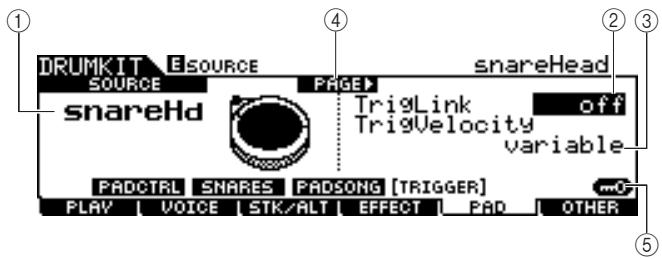
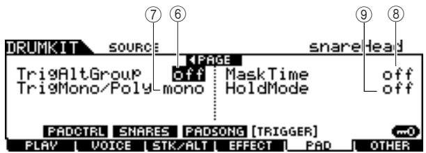
① SOURCE (Trigger Input Source)
Determines the Trigger Input Source to be edited. You can change the Trigger Input Source by hitting the corresponding pad when Input Lock is turned off.
| Settings | Refer to the Trigger Input Source List on page 61. |
② TrigLink(Trigger Link)
When any other value than "off" is selected here, different Trigger Input Sources (on the same pad) can generate the Trigger Signals simultaneously by simply hitting a certain Trigger Input Source. Keep in mind that the available values (Trigger Input Source) differ depending on the Trigger Input Source specified at ①.
| Settings | off, head, rim1, rim2, rim1&2, bow, pad11 |
NOTE
- When SOURCE is set to "hhFtCl," "hhSplsh," or "pad11," the Trigger Link parameter is not available.
③ TrigVelocity (Trigger Velocity)
Determines the value of velocity generated by hitting the pad corresponding to the SOURCE specified at ①. When "variable" is selected, the velocity value is determined by your hitting strength. When a value between "1" - "127" is selected, the corresponding value is used as the velocity regardless of your hitting strength.
| Settings | variable, 1 – 127 |
④ PAGE
This appears when another page can be called up from the current page. Use the Cursor [>] or [<] button to call up another page.
⑤ [SF6] Input Lock
You can turn Input Lock on or off by pressing this button. When Input Lock is turned on (the [L] indicator appears at the top right of the display), the Trigger Input jack ① cannot be changed even if you hit any pad. This function is useful when you want to adjust the parameters of the current pad (connected to the current Trigger Input jack) while hitting other pads.
⑥ TrigAltGroup (Trigger Alternate Group)
Determines the Alternate Group to which the Trigger Input Source is assigned. If multiple Trigger Input Source are grouped with the same number assigned, only one input from that group is enabled at a time. When a Trigger Input Source is enabled from a trigger alternate group, other Trigger Input Source from the same group respectively generate a MIDI note off event for the corresponding MIDI note number. The RcvKeyOff parameter for the drum Voice (10 ch) should be set to "on" in the display called up via the [DRUM KIT] [F2] VOICE [SF4] OTHER.
Up to 32 Alternate Groups can be defined. You can also select "off" here if you wish to allow the simultaneous playback of sounds.
| Settings | off, 1 – 32 |
⑦ TrigMono/Poly (Trigger Mono/Poly)
Determines whether the current Trigger Input Source is played back monophonically or polyphonically. If "mono" is selected, triggering the same Voice continuously will stop the previous sound, then start the same Voice sound. Note that the previous sound is stopped by a note off message, unlike the Mono/Poly parameter in the display called up via the [DRUM KIT] [F2] VOICE [SF4] OTHER. Accordingly, the RcvKeyOff parameter for the Voice (current Trigger Input Source) should be set to "on" in the display called up via the [DRUM KIT] [F2] VOICE [SF4] OTHER. If "Poly" is selected, there is no such limitation.
| Settings | mono, poly |
⑧ Mask Time
Determines the amount of time within which the DTX900 does not accept the Trigger Signal from the current Trigger Input Source after you hit the corresponding pad. When this parameter is set to "2.0s" for example, the DTX900 ignores the Trigger Signal for two seconds after you hit the corresponding pad.
| Settings | off, 20ms, 40ms – 10.00s (by 20ms), 20.00s, 30.00s |
⑨ Hold Mode
This parameter is normally set to "off," so that that hitting the same pad (current Trigger Input Source) only triggers (starts) the corresponding Voice sound. On the other hand, when set to "on," hitting the same pad alternately both triggers and stops the corresponding Voice sound. Because note off messages are used for stopping the Voice sound, you need to set the RcvKeyOff parameter to on in the display called up via [DRUM KIT] [F2] VOICE [SF4] OTHER.
| Settings | off, on |
Other Settings
[F6] OTHER
Settings Common to the Entire Drum Kit
[SF1] COMMON
From this display, you can set the parameters applied to the entire sound of the current Drum Kit.
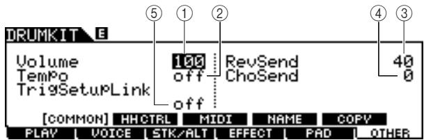
① Volume
Determines the volume of the entire Drum Kit.
Range
0-127
② Tempo
Determines the tempo value called up when you select the current Drum Kit. When "off" is selected, the tempo value is maintained when you select the current Drum Kit.
Range
off, 30-300
③ RevSend (Reverb Send)
Determines the Reverb depth applied to the Drum Kit. This parameter offsets the same parameter for each of the Drum Voices assigned to the current Drum Kit.
Range
0-127
④ ChoSend (Chorus Send)
Determines the Chorus depth applied to the Drum Kit. This parameter offsets the same parameter for each of the Drum Voices assigned to the current Drum Kit.
Range
0-127
⑤ TrigSetupLink (Trigger setup link)
Use this parameter to specify the trigger setup to be used when the current kit is selected. A trigger setup can be assigned to each different drum kit. Select "off" if the currently selected drum kit does not need a special trigger setup.
Settings
off, PRE:01 - 09, USR:01 - 05
NOTE
- If TrigSetupLink is set to "off," the trigger setup selected on the Utility mode will be loaded by default whenever the DTX900 is turned on. (See page 125.) Following this, the trigger setup can be freely changed in the Trigger Mode. (See page 108.)
Hi-Hat Controller Settings
[SF2] HH CTRL
From this display, you can set the parameters related to the Hi-Hat Controller (Foot Controller) connected to the HI-HAT jack (page 12).
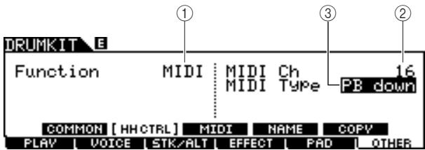
(1) Function
Determines the function assigned to the Hi-Hat Controller. When "Hi-Hat" is selected, you can use the Hi-Hat Controller normally for playing the hi-hat cymbal. When "MIDI" is selected, you can generate MIDI messages by pressing the Hi-Hat Controller according to the settings of the MIDI Ch parameter and MIDI Type parameter described below.
Settings
HiHat, MIDI
② MIDI Ch
Determines the MIDI channel over which operating the Hi-Hat Controller generates MIDI messages. This parameter is available only when the Function parameter is set to MIDI.
Settings
1-16
③ MIDI Type
Determines the type of MIDI messages generated by operating the Hi-Hat Controller. This parameter is available only when the Function parameter is set to MIDI. "Ctl000" - "Ctl119" represent Control Change messages, "AT" represents Aftertouch, "PB up" represents Pitch Bend upward (when pressing) and "PB down" represents Pitch Bend downward (when pressing).
Settings
Ctl000 - Ctl119, AT, PB up, PB down
MIDI Settings
[SF3] MIDI
From this display, you can perform the MIDI settings called up when the current Drum Kit is selected. According to the settings here, MIDI messages for 16 channels will be transmitted to the internal tone generator or the external MIDI device via MIDI when the current Drum Kit is selected. This display consists of five pages.
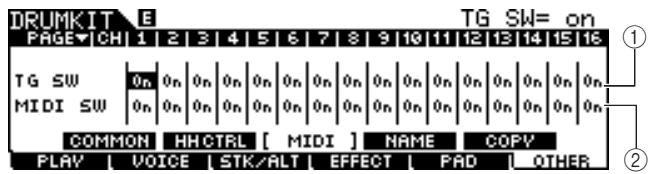
First page
① TG SW (Tone Generator Switch)
Determines whether or not the MIDI messages will be transmitted to the internal tone generator when the current Drum Kit is selected. When set to on, selecting the current Drum Kit transmits the MIDI messages for the corresponding channel to the internal tone generator according to the settings at ③ - ①.
| Settings | Off, On |
② MIDI SW (MIDI Switch)
Determines whether or not the MIDI messages will be transmitted to the external tone generator via MIDI OUT for each MIDI channel when the current Drum Kit is selected. When set to on, selecting the current Drum Kit transmits the MIDI messages for the corresponding channel to the external tone generator via MIDI OUT according to the settings at ③ - ⑪
| Settings | Off, On |
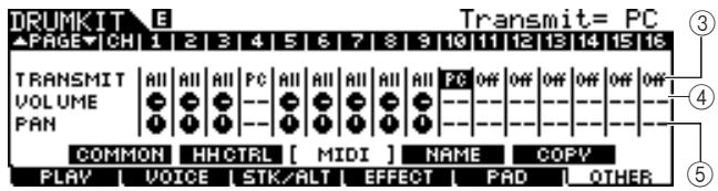
Second page
(3) TRANSMIT
Determines the type of MIDI messages transmitted to the internal tone generator or external MIDI device. When "off" is selected, no MIDI message will be transmitted even if the TG SW and MIDI SW parameters are set to on. When "all" is selected, both Program Change and Control Change messages will be transmitted. When "PC" is selected, only Program Change messages will be transmitted.
| Settings | Off, All, PC |
(4) VOLUME
Determines the value of the Volume (Control Change number 7) for each MIDI channel.
| Range | 0 – 127 |
⑤ PAN
Determines the value of the Pan (Control Change number 10) for each MIDI channel.
| Range | L63 (far left) – C (center) – R63 (far right) |
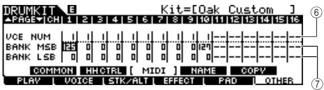
Third page
VCE NUM (Voice Number)
Determines the Program Change number for each MIDI channel.
Settings 1-128
(7) BANK MSB/LSB
Determines the Program Change number (by Bank MSB/LSB values) for each MIDI channel.
Settings 0-127
NOTE
- For details about the Bank MSB, Bank LSB and Program Change messages and how they determine the Voice of the DTX900, refer to the Voice List in the separate Data List booklet.
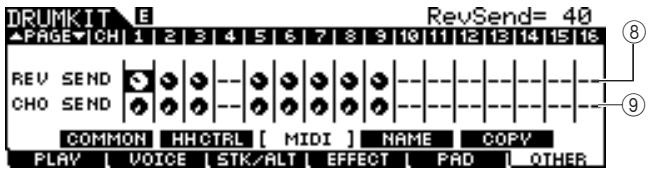
Fourth page
⑧ REV SEND (Reverb Send)
Determines the value of the Reverb Send Level (Control Change number 91) for each MIDI channel.
Range 0-127
⑨ CHO SEND (Chorus Send)
Determines the value of the Chorus Send Level (Control Change number 93) for each MIDI channel.
Range 0-127
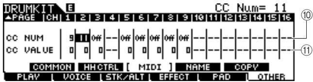
Fifth page
10 CC NUM
Determines the Control Change number for each MIDI channel.
Settings Off, 1-95
(1) CC VALUE
Determines the value of the specified Control Change number for each MIDI channel.
Range 0-127
NOTE
- If you set a Control change event ⑩ that duplicates the VOLUME ④ , PAN ⑤ , REV SEND ⑧ , or CHO SEND ⑨ setting, the Control Change event ⑩ will take priority.
Naming the Drum Kit
[SF4] NAME
From this display, you can assign an original name to the Drum Kit.
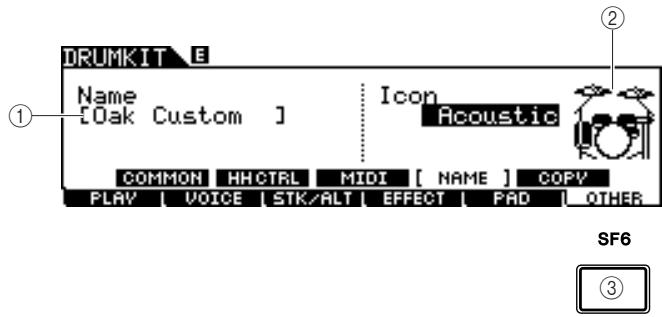
① Name
Enters the characters of the Drum Kit name (up to 12). You can call up the Character List by pressing the [SF6] LIST button and enter the name. For detailed instructions on naming, refer to "Basic Operation" on page 15.
② Icon
Determines the Drum Kit icon shown on the [F1] PLAY display. When "off" is selected, no icon will be shown in the [F1] PLAY display.
Settings
Acoustic, Rock, Electric, Percuss, Rhythm-Box, Effect, R&B/H-Hop, PadSong, off
③ [SF6] LIST
When the cursor is located on the Name box, you can call up the Character List by pressing the [SF6] LIST button and enter the name. For detailed instructions on naming, refer to "Basic Operation" on page 15.
Copying the Parameter Settings
[SF5] COPY
From this display, you can copy the parameter settings from the specified Trigger Input jack/Trigger Input Source/MIDI note of the specified Drum Kit to the specified Trigger Input jack/Trigger Input Source/MIDI note of the specified User Drum Kit.
After setting the parameters of copy source and destination, press the [ENTER/STORE] button to perform the Copy operation.
The available parameters differ depending on the value of the Type parameter located at the left top corner.
When the Type is set to "Input" (Trigger Input jack):
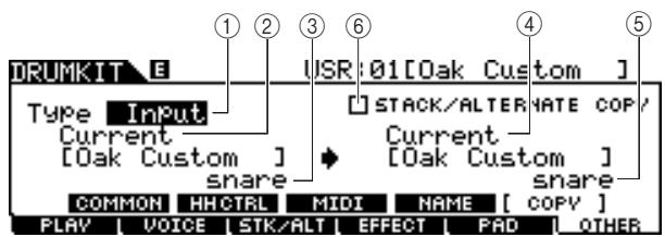
When the Type is set to Source:

When the Type is set to MIDl:
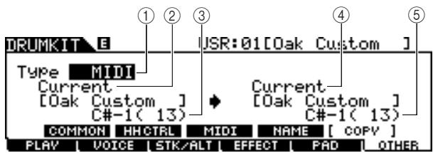
① Type
Determines which segment is used as copy source and copy destination: the Trigger Input jack (Voice Set), Trigger Input Source (Voice) or MIDI (MIDI note).
| Settings | Input (Trigger Input jack), Source (Trigger Input Source), MIDI |
② Source Drum Kit number
Determines the Drum Kit number used as the source. "Current" means the currently edited Drum Kit.
| Settings | Current, PRE: 01 – USR: 50 |
③ Copy Source
Determines the source of the Copy operation. When the Type is set to "Input," this parameter determines the Trigger Input jack used as the source. When the Type is set to "Source," this parameter determines the Trigger Input Source used as the source. When the Type is set to "MIDI," this parameter determines the MIDI note name used as the source.
(4) Destination Drum Kit number
Determines the Drum Kit number used as the destination. "Current" means the currently edited Drum Kit.
| Settings | Current, USR: 01 – 50 |
⑤ Copy Destination
Determines the destination of the Copy operation. When the Type is set to "Input," this parameter determines the Trigger Input jack used as the destination. When the Type is set to "Source," this parameter determines the Trigger Input Source used as the destination. When the Type is set to "MIDI," this parameter determines the MIDI note name used as the destination.
(6) STACK/ALTERNATE COPY
When this checkmark is entered to this box, the Stack/Alternate settings are also copied. When this checkmark is removed from this box, the Stack/Alternate settings are not copied, with the exception of the first note setting. Keep in mind that this parameter is not available when the Type is set to "MIDI."
Song Mode
This chapter explains the Song mode called up via the [SONG] button.
In the Song mode, you can select a desired Song from the Preset Songs (PRE: 01 - 87) for performing and practicing along with, and another 50 User Songs (USR: 01 - 50) for recording and editing your own songs. In addition, you can select one of the SMF Songs (EXT: 01 - 99) saved to an external USB storage device connected to the USB TO DEVICE terminal. These Songs can be called up directly even though they are stored in the external device.
NOTE
- In addition to the Song selected in the Song mode and started/stopped via the [▶/■] button on the panel, you can use Pad Songs which let you start the specified Song by hitting the pad. For more information about Pad Songs, see page 93.
NOTICE
- Song data recorded in the Song Record mode and edited in the Song Job mode resides in the DRAM temporarily, meaning that it will be lost by turning the power off. Make sure to save the Song data in the File mode to an external USB storage device connected to the USB TO DEVICE terminal before turning the power off.
Song Play
[F1] PLAY
Explanations about the display called up via the [SONG] [F1] PLAY are described on page 35 in the Quick Guide.
Song Recording
[F1] PLAY [REC]
Explanations about the Song Record mode called up via the [SONG] [F1] PLAY [REC] are described on page 43 in the Quick Guide.
Song Jobs
[F2] JOB
The Song Job mode contains a comprehensive set of editing tools and data transform functions you can use to change the sound of the Song. It also includes a variety of convenient operations, such as copying or erasing data.
| Functions | Descriptions |
| [SF1] SONG | Song Job |
| 01: Copy Song | This Job copies all data from a selected source Song to the current Song. |
| 02: Clear Song | This Job clears all data from the current Song. |
| 03: Song Name, Tempo, Repeat | This Job lets you set the name, tempo and repeat on/off settings for the current Song. |
| [SF2] TRACK | Track Job |
| 01: Quantize | This job (applied to the current Song and specified track) adjusts the timing of note events by moving them closer to the nearest exact beat. |
| 02: Mix Track | This job mixes all data from both tracks 1 and 2 of the current Song to either track 1 or 2 of the current Song. |
| 03: Copy Track | This job copies all data from the specified track of the specified Song to the specified track of the current Song. |
| 04: Clear Track | This job clears all data from the specified track of the current Song. |
| [SF3] MEAS | Measure Job |
| 01: Copy Measure | This job copies all data from the specified measure range of the specified track of the specified Song to the specified measure range of the specified track of the current Song. |
| 02: Create Measure | This job creates empty measures at the specified location in the specified track or tracks of the current Song. |
| 03: Delete Measure | This job deletes the specified measures of the current Song. |
| 04: Erase Measure | This job clears all data from the specified measure range of the current Song, producing a segment of silence. |
| [SF4] VOICE | Voice Job |
| This job sets tone generator parameters, such as voice, volume and pan, for all 16 MIDI channels. | |
Basic Procedure in the Song Job Mode
In the Song mode, select the desired User Song (to which you want to apply the Job) then press the [F2] JOB button to enter the Song Job mode.
NOTE
- Keep in mind that the Song Job mode can be entered only when a User Song is selected.
2 Select the desired Job menu by pressing one of the [SF1] - [SF4] buttons.
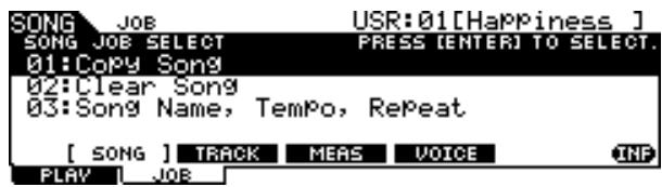
3 Move the cursor to the desired Job by using the data dial, cursor buttons, [INC/ YES] and [DEC/NO] buttons, then press the [ENTER/STORE] button to call up the Job display.
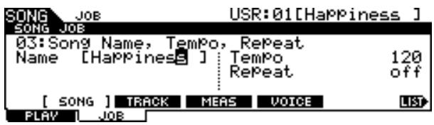
Pressing the [EXIT] button returns to the Job menu display.
4 Move the cursor to the desired parameter, then set the value by using the data dial, [INC/YES] and [DEC/NO] buttons.
NOTICE
- Keep in mind that executing the Job will result in loss of your original data, since any data once changed by executing the Job cannot be restored.
NOTICE
- In some Jobs, the operation overwrites any data previously existing in the destination memory. Important data should always be saved to a USB storage device connected to the USB TO DEVICE terminal.
5 After setting, press the [ENTER/STORE] button to execute the Job.
6 Save the Song to a USB storage device in the File mode.
For details, see pages 54 and 114.
NOTICE
- Song data created by executing the Job resides in the DRAM temporarily, meaning that it will be lost by turning the power off. Make sure to save the Song data in the File mode to an external USB storage device connected to the USB TO DEVICE terminal before turning the power off.
Song Jobs
[SF1] SONG
01: Copy Song
This Job copies all data from a selected source Song to the current Song.
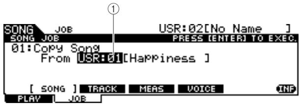
① Song number
Determines the source Song number to be copied. The corresponding Song name is shown at right of the Song number.
Settings PRE:01-87,USR:01-50
02: Clear Song
This Job clears all data from the current Song.
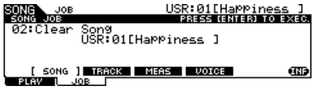
NOTE
- If you want to clear the track data instead of the entire Song, use the Clear Track Job on page 101.
03: Song Name, Tempo, Repeat
This Job lets you set the name, tempo and repeat on/off settings for the current Song.
NOTE
- Keep in mind that the pressing the [ENTER/STORE] button (executing the Job) is not necessary for the Song Name, Tempo, Repeat job.

① Name
Enters the characters of the current Song name (up to 10). You can call up the Character List by pressing the [SF6] LIST button and enter the name. For detailed instructions on naming, refer to "Basic Operation" on page 15.
② Tempo
Determines the tempo called up when the current Song is selected.
| Range | 30 – 300 |
③ Repeat
Determines whether or not Song playback is repeated. Setting this parameter to on plays the current Song repeatedly, while setting this parameter to off plays through the current Song to the end, then stops.
| Settings | off, on |
④ [SF6] LIST
When the cursor is located on the Name box, you can call up the Character List by pressing the [SF6] LIST button and enter the name. For detailed instructions on naming, refer to "Basic Operation" on page 15.
Track Jobs
[SF2] TRACK
01: Quantize
This job (applied to the current Song and the specified track) adjusts the timing of note events by moving them closer to the nearest exact beat.
NOTICE
- Keep in mind that executing this Job may irrevocably change the rhythm feeling of your original performance (such as intentional early or late hits), because once the data is changed by executing the Job, it cannot be restored.
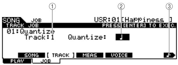
① Track
Determines the track (1 or 2) to which Quantize is applied.
| Settings | 1, 2 |
② Quantize (Resolution)
Determines the note timing to which the note data will be aligned. You can select the desired value by pressing the [SF6] button to call up the value list.
| Settings | When “3/8”, “6/8”, “9/8”, “12/8” or “15/8” is selected: 16th note triplet, 16th note, 8th note triplet, 8th note, 1/4 note, dotted 1/4 note When another value is selected: 16th note triplet, 16th note, 8th note triplet, 8th note, 1/4 note triplet, 1/4 note |
F 16th note triplet
F 16th note
8th note triplet
8th note
1/4 note triplet
1/4 note
Dotted 1/4 note
③ [SF6] (note type icon)
When the cursor is located on the Quantize value, the note type icon is shown at the tab menu corresponding to the [SF6] button. In this condition, you can call up a list of the note type icons by pressing the [SF6] button, then select the desired item from the list.
02: Mix Track
This job mixes all data from both tracks 1 and 2 of the current Song to either track 1 or 2 of the current Song.
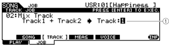
① Track
Determines the track (1 or 2) to which the mixed track is copied. The track which is not selected here will have no data after executing the Mix Track Job.
| Settings | 1, 2 |
03: Copy Track
This job copies all data from the specified track of the specified Song to the specified track of the current Song.
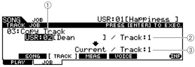
① Source Song number
Determines the copy source Song number.
| Settings | PRE: 01 - 87, USR: 01 - 50 |
NOTE
- The songs "EXT: 01" - "EXT: 99" (SMF songs saved in the root directory of the USB storage device connected to the USB TO DEVICE terminal) cannot be selected here.
② Source Track number
Determines the copy source track number of the Song specified at ①.
| Settings | 1, 2 |
③ Destination Track number
Determines the destination track number of the current Song.
| Settings | 1, 2 |
NOTICE
- This Job overwrites any data already existing in the destination track.
04: Clear Track
This job clears all data from the specified track of the current Song.
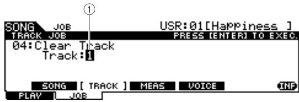
① Track
Determines the track number to be cleared.
| Settings | 1, 2 |
Measure Jobs
[SF3] MEAS
NOTE
- When the cursor is located at a measure-related parameter, "NUM" is indicated in the tab corresponding to the [SF6] button, meaning that you can use the [F1] - [F6] buttons and the [SF1] - [SF5] buttons as numeric key pads by pressing the [SF6] NUM button.
01: Copy Measure
This job copies all data from the specified measure range of the specified track of the specified Song to the specified measure range of the specified track of the current Song.
NOTICE
- This Job overwrites any data already existing in the destination measure range of the track.
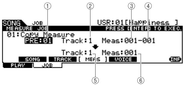
① Source Song number
Determines the source Song number.
| Settings | PRE: 01 - 87, USR: 01 - 50 |
② Source Track number
Determines the source track number of the Song number specified at ①.
| Settings | 1, 2 |
③ Starting measure number of source measure range
Determines the starting measure of the source measure range.
| Range | 001 – 999 |
(4) Ending measure number of source measure range
Determines the ending measure of the source measure range.
| Range | 001 – 999 |
⑤ Destination Track number
Determines the destination track number of the current Song.
| Settings | 1, 2 |
(6) Destination measure number
Determines the starting measure of the destination measure range.
| Range | 001 – 999 |
02: Create Measure
This job creates empty measures at the specified location in the specified track or tracks of the current Song. When empty measures are inserted, measure and meter data following the insert point are moved backward accordingly.
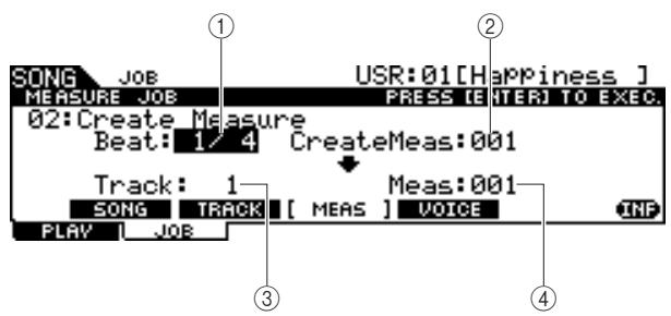
① Beat
Determines the time signature of the newly created (inserted) measure.
| Settings | 1/4 – 16/4, 1/8 – 16/8, 1/16 – 16/16 |
(2) Number of measures to be inserted
Determines the number of empty measures to be created and inserted.
| Settings | 001 – 999 |
③ Track
Determines the track to which this Job is applied. When "1+2" is selected, executing the Job adds the new measures to both the two tracks, with the result that the length of two tracks becomes the same. When "1" or "2" is selected, executing the Job adds new measures only to track 1 or 2, with the result that the length of the two tracks will be different.
| Settings | 1+2, 1, 2 |
Meas (Insertion point)
Determines the insertion point (measure number) at which the newly created blank measures will be inserted.
| Range | 001 – 999 |
03: Delete Measure
This job deletes the specified measures of the current Song. Measure and meter data following the deleted measures are moved forward accordingly.
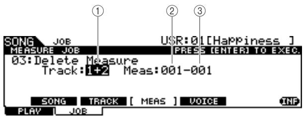
① Track
Determines the track number to be deleted. When "1+2" is selected, executing the Job removes the specified measures from both the two tracks, with the result that the length of two tracks becomes the same. When "1" or "2" is selected, executing the Job removes the specified measures only from track 1 or 2, with the result that the length of the two tracks will be different.
| Settings | 1+2, 1, 2 |
(2) Starting measure number of measure range
Determines the starting measure of the measure range to be deleted.
| Range | 001 – 999 |
(3) Ending measure number of measure range
Determines the ending measure of the measure range to be deleted.
| Range | 001 – 999 |
04: Erase Measure
This job clears all data from the specified measure range of the current Song, producing a segment of silence.
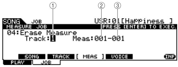
① Track
Determines the track number to be erased.
| Settings | 1, 2 |
(2) Starting measure number of measure range
Determines the starting measure of the measure range to be erased.
| Range | 001 – 999 |
(3) Ending measure number of measure range
Determines the ending measure of the measure range to be erased.
| Range | 001 – 999 |
Voice Job
[SF4] VOICE
This job sets tone generator parameters, such as voice, volume and pan, for all 16 MIDI channels. According to the settings here, the parameter values for all MIDI channels are transmitted to the internal tone generator or external tone generator via MIDI OUT when the current Song is selected.
This Job display consists of three pages.
NOTE
- Keep in mind that the pressing the [ENTER/STORE] button (executing the Job) is not necessary for the Voice Job.
The first page of the Voice Job
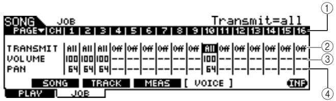
① CH
Indicates the MIDI channel.
② TRANSMIT
Determines whether or not the MIDI messages will be transmitted to the internal and external tone generator when the current Song is selected. When set to All, selecting the current Song transmits all MIDI messages for the corresponding channel to the internal and external tone generator according to the settings made at ③ - ⑫ . When set to PC, selecting the current Song transmits only the Voice-related settings made at ⑤ - ⑥ . When set to off, selecting the current Song transmits no MIDI messages and the following parameters ③ - ⑫ are not available.
| Settings | Off, All, PC |
(3) VOLUME
Determines the value of the Volume (Control Change number 7) for each MIDI channel.
| Range | 0 – 127 |
(4) PAN
Determines the value of the Pan (Control Change number 10) for each MIDI channel.
| Range | 0 – 127 |
The second page of the Voice Job
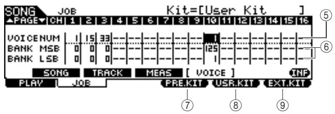
⑤ VOICE NUM (Voice Number)
Determines the Program Change number for each MIDI channel.
| Range | 1 – 128 |
⑥ BANK MSB/LSB
Determines the number of the Bank Select MSB and LSB for each MIDI channel. You can specify a specific Voice by setting the Bank Select MSB, LSB and Program Change (Voice number).
| Range | 0 – 127 |
NOTE
- If you set the Bank Select for MIDI channel 10 to 125 or 127, the Program Change number (Drum Kit number) set for MIDI channel 10 will be automatically applied to ALL other MIDI channels for the internal tone generator.
(7) [F4] PRE.KIT
This menu appears only when the cursor is located on any of the VCE NUM, BANK MSB, and BANK LSB settings of channel 10. Pressing this button calls up the Bank Select MSB and LSB values corresponding to the Preset Drum Kit of the DTX900.
[8] [F4] USR.KIT
This menu appears only when the cursor is located on any of the VCE NUM, BANK MSB, and BANK LSB settings of channel 10. Pressing this button calls up the Bank Select MSB and LSB values corresponding to the User Drum Kit of the DTX900.
[9] [F4] EXT.KIT
This menu appears only when the cursor is located on any of the VCE NUM, BANK MSB, and BANK LSB settings of channel 10. Pressing this button calls up the Bank Select MSB and LSB values corresponding to the External Drum Kit of the DTX900.
The third page of the Voice Job
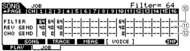
10 FILTER
Determines the value of the Brightness (Control Change number 74) for each MIDI channel.
| Range | 0 – 127 |
⑪ REV SEND (Reverb Send)
Determines the value of the Reverb Send Level (Control Change number 91) for each MIDI channel.
| Range | 0 – 127 |
⑫ CHO SEND (Chorus Send)
Determines the value of the Chorus Send Level (Control Change number 93) for each MIDI channel.
| Range | 0 – 127 |
This chapter explains the Click mode called up via the [CLICK] button.
In the Click mode, you can set the Click (Metronome) related parameters such as Click Voice, time signature and tempo for the entire DTX900. In addition, you can use the Groove Check function and Rhythm Gate function for rhythm training and practice.
Basic Procedure in the Click Mode
Press the [CLICK] button to enter the Click mode.
2 Note the tab menus (corresponding to the [F1] – [F5] and [SF1] – [SF3] buttons) to find the desired function, then press the relevant button to call up the desired display.
3 Move the cursor to each parameter, then set the value by using the data dial, [INC/YES] and [DEC/NO] button.
4 After setting, press the [ENTER/STORE] button to store all the settings in the Click mode, other than tempo, beat (time signature) and subdivide.
NOTICE
- All the settings in the Click mode will be lost if the power is turned off without storing.
- Never attempt to turn off the power while the message "Please keep power on" is shown on the display; otherwise, all the settings in the Click mode may be lost.
Basic Settings of the Click Sound
[F1] PLAY
From this display, you can set the basic parameters of the Click sound such as Voice, time signature and tempo.
NOTE
The note types shown in VOLUME will differ depending on the BEAT settings.
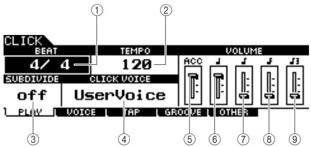
① BEAT (Time Signature)
Determines the time signature of the Click sound.
Settings 1/4 - 16/4, 1/8 - 16/8, 1/16 - 16/16
NOTE
- When a Song having a different Beat (time signature) setting is selected in the Song mode, the Beat of the new Song is applied also to the Click sound.
② TEMPO
Determines the tempo of the Click sound.
| Settings | 030 – 300 |
NOTE
- When a Song having a different tempo setting is selected in the Song mode, the tempo value of the new Song is applied also to the Click sound.
- The tempo can also be set using the Tap Tempo function, letting you set the tempo by tapping it on a pad. With this, you can conveniently set the tempo to one that feels best to you. For details, see page 34.
③ SUBDIVIDE
Determines the accent beat of the Click. Beats are divided at the accent beat specified here. When BEAT is set to "5/4," SUBDIVIDE is set to "2+3," the accent is applied to the first beat and the third beat. When BEAT is set to "9/4," SUBDIVIDE is set to "4+5," the accent is applied to the first beat and the fifth beat.
| Settings | off, 2+3, 3+2, 3+4, 4+3, 4+5, 5+4, 5+6, 6+5, 6+7, 7+6, 7+8, 8+7 |
(4) CLICK VOICE
Determines the Click Voice.
| Settings | Metronome, Claves, Cowbell, Shaker, Stick, CrossStick, Pulse, Human, UserVoice |
⑤ VOLUME (ACC)
For adjusting the volume of the accent beat determined by the SUBDIVIDE parameter.
| Range | 0 – 127 |
⑥ VOLUME (quarter note)
Determines the volume of click timing for quarter notes.
| Range | 0 – 127 |
⑦ VOLUME (eighth notes)
Determines the volume of click timing for eighth notes.
| Range | 0 – 127 |
VOLUME (sixteenth notes)
Determines the volume of click timing for sixteenth notes.
| Range | 0 – 127 |
VOLUME (eighth note triplet)
Determines the volume of click timing for eighth note triplet notes.
| Range | 0 – 127 |
Click Voice Settings
[F2] VOICE
From this display (available only when the Click Voice is set to "User Voice"), you can set a different Click Voice for each beat timing.
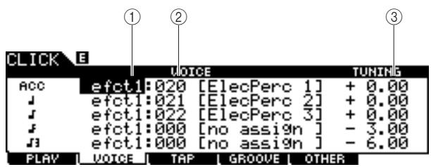
① Voice category
Determines the voice category for the click sound.
| Settings | kick1 - 2, snare1 - 3, tom1 - 2, cymbal, hihat, perc1 - 2, efct1 - 2, USR-A - H |
② Voice number
Determines the voice number for the click sound. If the voice number is set to "000," the indication "no assign" is shown for the voice name and no sound will be produced.
Settings
Refer to the separate Data List booklet.
NOTE
- The amount of Voices differs depending on the selected Voice category.
③ TUNING
Determines the pitch of the Voice specified at ②.
| Range | -24.00 – +24.00 (1.0 indicates one semi-tone.) |
NOTE
- A User Voice assigned to a Click Voice will be played back with just one shot, even if the User Voice is set to "loop" in the Sampling mode.
- When you want to use the Click Voice having a User Voice, it is a good idea to save the file including your desired User Voice in the AUTOLOAD folder (page 125) of the USB storage device and use the Auto Load function (page 125).
Tap Tempo Function
[F3] TAP
The Tap Tempo function is described in the Quick Guide section on page 34.
Groove Check Function
[F4] GROOVE
Performing the Groove Check
[SF1] G.CHECK
Explanations about this display are described in the Quick Guide section on page 51.
Performing the Rhythm Gate
[SF2] R.GATE
Explanations about this display are described in the Quick Guide section on page 52.
Parameter Settings for the Groove Check and Rhythm Gate
[SF3] SETTING
Explanations about this display are described in the Quick Guide section on page 50.
Click Sound Settings
[F5]OTHER
Setting How the Click Sound is Played
[SF1] OUTPUT
From this display, you can set the parameters which determine under what circumstances the click and the output for the click sound.
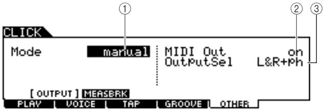
① Mode
Determines how and under what circumstances the click is played. The click can be started or stopped in synchronization with song playback/recording according to the setting here, as well as by pressing the [CLICK ON/OFF] button.
| Settings | manual, play, rec, play&rec |
| manual | The Click is started/stopped only by pressing the [CLICK ON/OFF] button. |
| play | The Click is started/stopped by starting/stopping the Song playback, as well as by pressing the [CLICK ON/OFF] button. |
| rec | The Click is started/stopped by starting/stopping the Song recording, as well as by pressing the [CLICK ON/OFF] button. |
| play&rec | The Click is started/stopped by starting/stopping the Song playback/recording, as well as by pressing the [CLICK ON/OFF] button. |
② MIDI Out
Determines whether or not the MIDI note number corresponding to the Click Voice is transmitted via MIDI OUT. When this parameter is set to on, the following MIDI events are transmitted via MIDI OUT.
| MIDI channel | Note | Velocity | |
| Accent note | 10 | B#-1 | 127 |
| 1/4 note | 10 | C0 | 127 |
| Other notes | 10 | B-1 | 127 |
| Settings | off, on |
NOTE
- The MIDI note events corresponding to the Click sound will be transmitted via MIDI OUT only when the Click sound is produced. The MIDI note events corresponding to the Click sound for which the Volume is turned down to the minimum level on the [F1] PLAY display will not be transmitted via MIDI OUT. Likewise, the MIDI note events corresponding to the Click sound during "Break" of the Measure Break function will not be transmitted via MIDI OUT.
③ OutputSel (Output Select)
Determines the output jack for the click sound.
| Settings | L&R+ph (OUTPUT and PHONES), Phones (PHONES), L&R (OUTPUT), ind1&2 – ind5&6 (INDIVIDUAL OUTPUT 1 and 2 – 5 and 6), ind1 – ind6 (one of the INDIVIDUAL OUTPUTs) |
Using the Measure Break Function
[SF2] MEASBRK
From this display, you can set the parameters related to the Measure Break function. By using this function, the Click Voice can be played back for specified measures and muted for specified measures repeatedly.
This function can be effectively used to bring your rhythm technique and timing up to a higher level—letting you play a certain drum phrase for several measures while listening to the Click Voice, then play the next several measures with no Click sound. For example, to have four measures with the Click Voice followed by four measures without, set the Measure parameter to 4 and the Break parameter to 4.
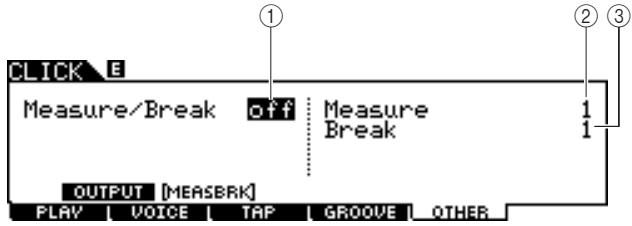
① Measure/Break
Determines whether the Measure Break function is active or not. When set to on, the Click Voice is played back for measures specified at ② and muted for measures specified at ③ repeatedly.
| Settings | off, on |
② Measure
Determines the amount of measure range within which the Click sound is played (not muted).
| Range | 1 – 9 |
③ Break
Determines the amount of measure range within which the Click sound is muted.
| Range | 1 – 9 |
This chapter explains the Trigger mode called up via the [TRIGGER] button.
In the Trigger mode, you can set the parameters related to the trigger signals received from the pads or Drum Triggers (such as Yamaha DT20) which are connected to the Trigger Input jacks. These settings let you optimize the DTX900 for best operation and response to the trigger signals. If you are using drum triggers attached to acoustic drums, or pads you've bought separately, you'll need to adjust the sensitivity and assign Voices to the individual Trigger Input Sources. This mode also has settings that help prevent crosstalk and double triggering.
* Crosstalk
A triggering problem in which the vibration generated by hitting a certain pad may cause unwanted triggering in another (usually adjacent) pad.
* Double triggering
A triggering problem in which two or more trigger signals may be generated simply by hitting a certain pad once.
NOTE
- Creating an appropriate Trigger Setup is necessary to get optimum results and obtain the expected response and sound when you hit the pads. One good way to ensure this is to find an existing Trigger Setup close to your favorite one, then edit it.
- Once you have found or created your favorite Trigger Setup, it is a good idea to assign the Trigger Setup number to the TriggerNo parameter in the display called up via the [UTILUITY] [F1] GENERAL [SF4] STARTUP. In this way, you can have your favorite Trigger Setup number automatically called up every time you turn the power on.
Refer to page 22 for details about the [SF6] Input Lock.
Basic Procedure in the Trigger Mode
Press the [TRIGGER] button to enter the TRIGGER mode.
TRIGGER

2 Note the tab menus (corresponding to the [F1] – [F5] and [SF1] – [SF2] buttons) to find the desired function, then press the relevant button to call up the desired display.
NOTE
- The Trigger Input jack, the level of the Trigger Signal and velocity are shown at the top of the display when one of the [F1]–[F4] displays is called up.
3 Move the cursor to each parameter, then set the value by using the data dial, or [INC/YES] and [DEC/NO] buttons.
4 After setting, press the [ENTER/STORE] button.
The following display will appear.
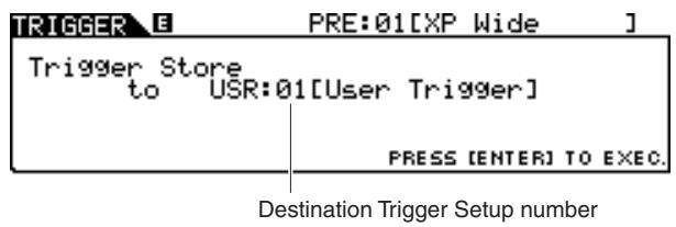
5 Select the destination Trigger Setup number by using the data dial.
6 Press the [ENTER/STORE] button.
The following display prompts you for confirmation before executing the store operation.

7 Press the [INC/YES] button to execute the Store operation.
NOTICE
- The edited Trigger Setup will be lost when selecting a different Trigger Setup or turning the power off. Make sure to store the Trigger Setup data to internal memory by pressing the [ENTER/STORE] button before selecting a different Trigger Setup or turning the power off.
NOTICE
- Never attempt to turn off the power while the message "Please keep power on" is shown on the display; otherwise, all the settings in the Trigger mode may be lost.
Selecting the Trigger Setup
[F1] SELECT
Explanations about this display is described in the Quick Guide section on page 22.
NOTE
- Keep in mind that each number in the display corresponds to the number of the Trigger Input jack printed at the top of the front panel. Above each number, the status of the trigger signal received from the pad is shown in real time.
Selecting the Pad Type
[F2] TYPE
From this display, you can set the type of pad or drum trigger connected to the Trigger Input jack. Make sure to select the appropriate type matching to the particular pad or drum trigger, in order to use it at its full potential.
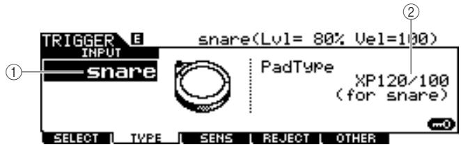
① INPUT (Trigger Input jack)
Determines a target Trigger Input jack. You can select the Trigger Input jack by hitting the desired pad when Input Lock (page 79) is turned off (when the L indicator is not shown at the right top of the LCD display).
| Settings | snare – pad15 |
② Pad Type
Determines the pad type for the Trigger Input jack specified at ①. The list below shows the pad types that can be set for the connected pads or drum triggers.
| Settings | KP125W, KP125, KP65, XP120/100 (for snare), XP120/100 (for tom), TP120SD/100 (for snare), TP120SD/100 (for tom), TP65S (for snare), TP65S (for tom), TP65S (for hihat), TP65, PCY155, PCY135, PCY150S, PCY130SC, PCY130S/130, PCY65S/65, RHH135, RHH130, DT10/20 (for snare), DT10/20 (for HiTom), DT10/20 (for LoTom), DT10/20 (for Kick), TRG Snare, TRG HiTom, TRG LoTom, TRG Kick |
NOTE
- When XP120SD/T, XP100SD/T, TP120SD/100 or TP65S is used as a snare pad, set the pad type to "for snare." As the sensitivity of the closed rim shot section increases, the closed rim shot will become easier to sound.
Trigger Sensitivity Settings
[F3] SENS
From this display, you can set the sensitivity-related parameters, which determine how the DTX900 responds to the trigger signals received via the Trigger Input jacks. In other words, the parameters here determine how the level of the trigger signal (strength of your hits) is converted to the velocity recognized by the tone generator block. Keep in mind that the level and velocity generated by hitting a pad are shown at the top of the LCD display in real time.
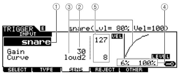
① INPUT (Trigger Input jack)
Determines a target Trigger Input jack. You can select the Trigger Input jack by hitting the desired pad when Input Lock (page 79) is turned off (when the L indicator is not shown at the right top of the LCD display).
| Settings | snare – pad15 |
② Gain
Determines the gain with which the DTX900 receives the trigger signal from the pad. The higher the value, the more easily you can get sound even when hitting the pad softly.
| Range | 0 – 63 |
③ Curve
Determines how the actual velocity will be generated and transmitted according to the level (strength) with which you hit the pad. The "loud2" curve, for example, provides increased response, especially for lower velocities. The "hard2" curve, for example, effectively lessens the overall response compared to the other curves.
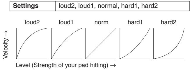
(4) LEVEL
Determines the level range within which the velocity is changed.
If the trigger signal is below the minimum level set here, no sound is produced. Even if the trigger signal exceeds the maximum level, the sound is produced with the maximum velocity and no greater.
| Range | minimum level: 0% – 99%, maximum level: 1% – 100% |
⑤ VEL (Velocity)
Determines the velocity range within which the Voice sound is produced.
| Range | minimum velocity: 0 – 126, maximum velocity: 1 – 127 |
Setting the Rejection
[F4] REJECT
From this display, you can set the Rejection-related parameters, letting you prevent "false hits"—such as double triggering caused by stick rebounds, and crosstalk cause by pad vibration. The trigger signals regarded as "false hits" will be ignored by proper setting of the Rejection parameters.
![YAMAHA DTX-900 - [F4] REJECT - 1](/content/2025/01/114986/images/7a38bc690f410cdd448f6bfa66015cf9bdb3805352631abe92a32c55062895a2.jpg)
① INPUT (Trigger Input jack)
Determines a target Trigger Input jack. You can select the Trigger Input jack by hitting the desired pad when Input Lock (page 79) is turned off (when the L indicator is not shown at the right top of the LCD display).
| Settings | snare - pad15 |
② Reject Time
Determines the amount of time within which the current Trigger Input jack will not accept new trigger signals from the moment receiving the previous trigger signal. The setting here prevents unexpected sounds generated via double triggering.
Range 4ms - 500ms
③ Reject Level From ALL
Determines the minimum level of the trigger signals (generated by hitting any other pads) which the current Trigger Input jack will accept. In other words, the current Trigger Input jack will not accept trigger signals (generated by hitting any other pads) having a level lower than that specified here. The higher the value, the less unexpected sounds are generated via crosstalk.
| Range | 0% – 99% |
④ Reject Level From ***
Determines the specific Trigger Input jack and the minimum level of the trigger signals (generated by hitting the pad corresponding to the Trigger Input jack specified here) which the current Trigger Input jack will accept. In other words, the current Trigger Input jack will not accept trigger signals (generated by hitting the pad corresponding to the Trigger Input jack specified here) having a level lower than that specified here. The higher the value, the less unexpected sounds are generated by crosstalk between the pad corresponding to the current Trigger Input jack and the pad corresponding to the Trigger Input jack specified here.
| Range | 0% – 99% |
| Settings | snare, tom1-4, ride, crash1-2, hijat, kick, pad11-15, tom1&2, tom1&3, tom2&3, tom2&4, tom3&4, tom2&3&4, tom all, cym all |
Setting example for preventing Crosstalk When the Crash1 sound is triggered even though only TOM1 is hit:
- Set INPUT to "crash1," set Reject Level From *** to "tom1," then turn Input Lock (page 79) to on by pressing the [SF6] button.
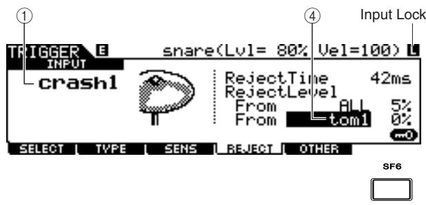
- Adjust the "tom1" value of Reject Level From so that the Crash1 sound is not triggered, even if hitting the pad connected to the TOM1 jack. The higher the value, the less likely the Crash1 sound will be accidentally triggered.
- After finding and setting the appropriate value, store the setting as a User Trigger Setup and turn Input Lock off so that you can play the drum performance.
NOTE
- If the "tom1" value of the Reject Level From is too large, the Crash1 sound may not be triggered properly when you hit both the Crash1 and Tom1 at the same time.
Other Settings
[F5]OTHER
Naming the Trigger Setup
[SF1] NAME
You can enter a name of up to 12 characters for the Trigger Setup currently being edited. For detailed instructions on naming, refer to "Basic Operation" on page 15.
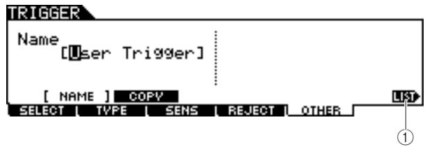
① [SF6] LIST
When the cursor is located on the Name box, you can call up the Character List by pressing the [SF6] LIST button and enter the name. For detailed instructions on naming, refer to "Basic Operation" on page 15.
Copying the Trigger Setup
[SF2] COPY
From this display, you can copy a Trigger Setup (from a specific Trigger Input jack of a specific Trigger Setup number) to the same or different Trigger Input jack of the same or different Trigger Setup number. For example, if you want to copy the Trigger Setup of the TOM1 jack to TOM4 within the current Trigger Setup, set the copy source to "Current" and "tom1," then set the copy destination to "Current" and "tom5," and execute the Copy operation. The Copy operation can be executed by pressing the [ENTER/STORE] button after making the parameter settings.
NOTICE
- When the Trigger Setup Copy operation is executed, the destination Trigger Setup will be replaced with the settings of the copy source.
NOTICE
- When setting the copy destination to "Current" and executing the Copy operation, make sure to store the current Trigger Setup by pressing the [ENTER/STORE] button on another display. This is necessary because the edited Trigger Setup will be lost when selecting a different Trigger Setup or when turning the power off; it also is necessary since the Store operation cannot be performed from the [SF2] COPY display.
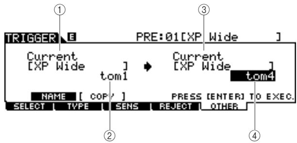
① Trigger Setup number as copy source
Determines the Trigger Setup number as copy source. "Current" refers to the currently edited Trigger Setup.
| Settings | Current, PRE: 01 – USR: 05 |
② Trigger Input jack as copy source
Determines the Trigger Input jack as copy source.
| Settings | snare – pad15 |
③ Trigger Setup number as copy destination
Determines the Trigger Setup number as copy destination. "Current" refers to the currently edited Trigger Setup.
| Settings | Current, USR: 01 – USR: 05 |
④ Trigger Input jack as copy destination
Determines the Trigger Input jack as copy destination.
| Settings | snare – pad15 |
This chapter explains the File mode called up via the [FILE] button.
The File mode provides tools for transferring data (such as Songs and User Voices) between the DTX900 and external storage devices, such as a USB storage device or hard disk drive connected to the USB TO DEVICE terminal.
Terminology in the File Mode
File
Just as with a computer, various data types such as Drum Kit, User Voice, Song and Trigger Setup created on the DTX900 can be treated as a file and saved to an external USB storage device. Each file features a file name and file extension.
File Name
Just as with a computer, you can assign a name to the file in the File mode. Files having the same name cannot be saved in the same directory.
File extension
The three letters following the file name (after the period) such as ".mid" and ".wav" are referred to as a file "extension." The extension indicates the type of file and cannot be changed by the panel operation of the DTX900. The File mode of the DTX900 supports ten different extension types, according to the particular data. For details, see page 113.
File size
This refers to the memory amount of the file. The file size is determined by the amount of data saved to the file. Generally, the size of an audio file (AIFF, WAV, etc.) is much larger than the size of a MIDI file. On the DTX900, the size of file including the User Voices (consisting of audio signals obtained via the Sampling function) is much larger than other files. File sizes are indicated in conventional computer terms by B (Byte), KB (Kilo Byte), MB (Mega Byte) and GB (Giga Byte). 1KB is equivalent to 1024 Byte, 1MB is equivalent to 1024KB, and 1GB is equivalent to 1024MB.
Device
Refers to a memory storage unit (such as a hard disk) to which the file is saved. The DTX900 can handle and mount various types of USB storage devices connected to the USB TO DEVICE terminal.
Directory (Folder)
This is an organizational feature on a data storage device (such as hard disk), allowing you to group data files together according to type or application. Directories can be nested in hierarchical order for organizing data. The "directory" is equivalent to the computer term "folder." The File mode of the DTX900 allows you to assign a name to a directory as with files. Please note that the directory name does not contain an extension.
Format
The operation of initializing a storage device (such as a hard disk) is referred to as "format." The File mode of the DTX900 allows you to format the USB memory storage device connected to the USB TO DEVICE connector. The format operation erases all data from the target memory device and automatically creates an "AUTOLOAD" directory.
Save/Load
"Save" means that the data created on the DTX900 is saved to an external memory device as a file, while "Store" means that the data created on the DTX900 is stored to internal memory. "Load" means that the file on the external memory device is loaded to internal memory.
File Types Compatible With the DTX900
The DTX900 supports various file types that can be saved and loaded.
File types that can be saved
| File types | File extension* | Information |
| AllData | .T3A | All data in this DTX900's internal User Memory (Flash ROM, DRAM and optionally installed DIMM) is treated as a single file, and can be saved to the USB storage device. |
| Utility | .T3U | Utility setup data in this DTX900's internal User Memory (Flash ROM) is treated as a single file, and can be saved to the USB storage device. |
| Click | .T3C | Click setup in this DTX900's internal User Memory (Flash ROM) is treated as a single file, and can be saved to the USB storage device. |
| AllTrigger | .T3T | All the Trigger Setup data in the DTX900's internal User Memory (Flash ROM) is treated as a single file, and can be saved to the USB storage device. |
| AllKit | .T3K | All the Drum Kit data in the DTX900's internal User Memory (Flash ROM) is treated as a single file, and can be saved to the USB storage device. |
| AllChain | .T3H | All the Chain data in the DTX900's internal User Memory (Flash ROM) is treated as a single file, and can be saved to the USB storage device. |
| AllSong | .T3S | All the Song data in the DTX900's internal User Memory (DRAM) is treated as a single file, and can be saved to the USB storage device. |
| AllVoice | .T3V | All the User Voice data in the DTX900's internal User Memory (DRAM) is treated as a single file, and can be saved to the USB storage device. |
| Wav | .WAV | A User Voice created in the Sampling mode can be saved to the USB storage device as a WAV file (Windows audio format). |
| Aiff | .AIF | A User Voice created in the Sampling mode can be saved to the USB storage device as an AIFF file (Macintosh audio format). |
File types that can be loaded
| File types | File extension* | Information |
| AllData | .T3A | Files of the “AllData” type saved to the USB storage device can be loaded and restored to the instrument. |
| Utility | .T3U | Files of the “AllData” or “Utility” type saved to the USB storage device can be loaded and restored to the instrument. |
| Click | .T3C | Files of the “AllData” or “Click” type saved to the USB storage device can be loaded and restored to the instrument. |
| AllTrigger | .T3T | Files of the “AllTrigger” type saved to the USB storage device can be loaded and restored to the instrument. |
| Trigger | .T3A | A specified Trigger Setup data in a file that is saved to the USB storage device as “AllData” or AllTrigger” type can be individually selected and loaded to the instrument. |
| .T3T | ||
| AllKit | .T3K | Files of the “AllKit” type saved to the USB storage device can be loaded and restored to the instrument. |
| Kit | .T3A | A specified Drum kit data in a file that is saved to the USB storage device as “AllData” or AllKit” type can be individually selected and loaded to the instrument. |
| .T3K | ||
| AllChain | .T3H | Files of the “AllChain” type saved to the USB storage device can be loaded and restored to the instrument. |
| Chain | .T3A | A specified Chain data in a file that is saved to the USB storage device as “AllData” or AllChain” type can be individually selected and loaded to the instrument. |
| .T3H | ||
| AllSong | .T3S | Files of the “AllSong” type saved to the USB storage device can be loaded and restored to the instrument. |
| Song | .T3A | A specified Song in a file that is saved to the USB storage device as “AllData” or “AllSong” type can be individually selected and loaded to the instrument. |
| .T3S | ||
| .MID | ||
| AllVoice | .T3V | Files of the “AllVoice” type saved to the USB storage device can be loaded and restored to the instrument. |
| Voice | .T3A | A specified Voice in a file that is saved to the USB storage device as “AllData” or AllVoice” type can be individually selected and loaded to the instrument. |
| .T3V | ||
| Wave | .WAV | WAV files (extension: .WAV) or AIFF files (extension: .AIF) can be loaded to the User Voice. |
| .AIF |
Saving a File
[F1] SAVE
NOTICE
While the data is being saved, make sure to follow these precautions:
- Never remove or eject the media from the device (USB storage).
- Never unplug or disconnect any of the devices.
- Never turn off the power of the DTX900 or the relevant devices.
Saving All User Data or All Data of a Specific Type
After connecting the USB storage device to the instrument, follow the instructions below.
Press the [FILE] button to enter the File mode, then press the [F1] SAVE button to call up the Save display.
![YAMAHA DTX-900 - Press the [FILE] button to enter the File mode, then press the [F1] SAVE button to call up the Save display. - 1](/content/2025/01/114986/images/e904847128b9f52af729b8ec0abadaa480dfed6f4be29090879010cc35285cc4.jpg)
① TYPE
Among the various types of data created on this instrument, you can save all of them or data created in each mode to a single file. This parameter determines which specific type of data will be saved to a single file.
| Settings | AllData, Utility, Click, AllTrigger, AllKit, AllChain, AllSong, AllVoice, Wav, Aiff |
② File name input location
You can enter a name of up to eight characters for the file you are about to save. For detailed instructions on naming, refer to "Basic Operation" on page 15.
③ Current
Indicates the current directory (folder). This indication is automatically changed according to the current directory (folder) specified in the File/Directory (Folder) selection box. The "root" directory is the highest directory.
④ File /Directory (Folder) selection box
Indicates the directories and files in the current Directory. In this box, the directories and files are listed in alphabetical order. Pressing the [ENTER/STORE] button enters the selected directory (folder) while pressing the [EXIT] button returns to the next highest directory.
You can distinguish the directory and file by the indicator at left end of each line.
Directory (Folder)
File
⑤ [SF1] EXEC
Pressing this button saves the file to the currently selected directory.
[SF2] SET NAME
Pressing this button copies the file/directory name selected from the File/Director (Folder) selection box to the File name input location.
(7) [F6] NEW
Pressing this button creates a new directory named "NEWDIR**" within the currently selected directory. You can change this name from the [F3] RENAME display.
2 Set the desired TYPE parameter to one of the following: "AllData," "Utility," "Click," "AllTrigger," "AllKit," "AllChain," "AllSong," or "AllVoice."
For details about each of the file types, see page 113.
3 Move the cursor to the file name input location, then input a file name.
For detailed instructions on naming, refer to "Basic Operation" on page 15. You can call up the Character List by pressing the [SF6] button.
4 Move the cursor to the File/Directorry selection box, then select the destination directory.
Pressing the [ENTER/STORE] button enters the selected directory (folder) while pressing the [EXIT] button returns to the next highest directory. When you want to save the file to the root directory and "root" is not shown as "Current Dir" at the right top of the display, press the [EXIT] button a few times to go to the root directory.
Press the [SF1] EXEC button to execute the Save operation.
If you are about to overwrite an existing file, the display prompts you for confirmation. Press the [INC/YES] button to execute the Save operation, or press the [DEC/NO] button to cancel it.
Saving the Audio Data Assigned to a User Voice as a WAV or AIFF File
You can save the audio data assigned to a User Voice as a WAV file (Windows audio format) or an AIFF file (Macintosh audio format). After connecting the USB storage device to the instrument, follow the instructions below.
Press the [FILE] button to enter the File mode, then press the [F1] SAVE button to call up the Save display.
![YAMAHA DTX-900 - Press the [FILE] button to enter the File mode, then press the [F1] SAVE button to call up the Save display. - 1](/content/2025/01/114986/images/92b9d5e689f0368ceb0f1bc9ea187f301a2b7e85f5cd802fcb9baa22e553cc05.jpg)
① TYPE
Among the various types of data created on this instrument, you can save all of them or data created in each mode to a single file. This parameter determines which specific type of data will be saved to a single file.
| Settings | AllData, Utility, Click, AllTrigger, AllKit, AllChain, AllSong, AllVoice, Wav, Aiff |
② File name input location
You can enter a name of up to eight characters for the file you are about to save. For detailed instructions on naming, refer to "Basic Operation" on page 15.
2 Move the cursor to TYPE, then select "Wav" or "Aiff" by using the data dial, [INC/YES] and [DEC/NO] button.
3 Move the cursor to the file name input location, then input a file name.
For detailed instructions on naming, refer to "Basic Operation" on page 15.
You can call up the Character List by pressing the [SF6] button.
4 Select the destination directory for saving, if you have created any directory.
Pressing the [ENTER/STORE] button enters the selected directory (folder) while pressing the [EXIT] button returns to the next highest directory. When you want to save the file to the root directory and "root" is not shown as "Current Dir" at the right top of the display, press the [EXIT] button a few times to go to the root directory.
5 Press the [SF1] EXEC button.
The User Voice bank and number to be saved appear on the left half of the display. You can select the Voice including the desired audio signals.
![YAMAHA DTX-900 - Press the [SF1] EXEC button. - 1](/content/2025/01/114986/images/96f1f26c97d5a9f547a8414b1778f158b92c81f88b78c15719a9a7f16852c224.jpg)
① User Voice bank and number
Determines the User Voice bank and number which includes the audio signals you want to save as a WAV file or AIFF file.
6 Select the User Voice bank and number including the audio signals you want to save as a WAV file or AIFF file.
7 Press the [SF1] EXEC button to execute the Save operation.
Loading a File
[F2] LOAD
NOTICE
- The Load operation overwrites any data previously existing in the destination internal memory. Important data should always be saved to a USB storage device connected to the USB TO DEVICE terminal.
NOTICE
While the data is being loaded, make sure to follow these precautions:
- Never remove or eject the media from the device (USB storage).
- Never unplug or disconnect any of the devices.
- Never turn off the power of the DTX900 or the relevant devices.
Loading All User Data or All Data of a Specific Type
Press the [FILE] button to enter the File mode, then press the [F2] LOAD button to call up the Load display.
![YAMAHA DTX-900 - Press the [FILE] button to enter the File mode, then press the [F2] LOAD button to call up the Load display. - 1](/content/2025/01/114986/images/99d87994d4840d5431cf9c54ee98846dd0e5ac8a319feb7c0c763bcf58af2c1f.jpg)
① TYPE
Among the various types of data saved in a single file on a USB storage device, you can load all of them at once or load only a specific type of data to this instrument. This parameter determines which specific type of data will be loaded from a single file.
| Settings | AllData, Utility, Click, AllTrigger, Trigger, ALLKit, Kit, ALLChain, Chain, ALLSong, Song, ALLVoice, Voice, Wave |
2 Move the cursor to TYPE, then set the desired File type to one of the following: "AllData," "AllTrigger," "AllKit," "AllChain," "AllSong," or "AllVoice."
Only available files according to the Type are listed in the Directory/File list box on the display.
3 Move the cursor to the Directory/File list box, then select the file to be loaded.
You can select any of the files listed in the Directory/File list box on the display.
4 Press the [SF1] EXEC button to execute the Load operation.
Loading a Specific Drum Kit From an "All Data" or "All Kit" File
You can also load a single, specific Drum Kit from the file (File extension: .T3A or T3K) to the desired User Drum Kit number.
Press the [FILE] button to enter the File mode, then press the [F2] LOAD button to call up the Load display.
2 Move the cursor to TYPE, then set the File type to "Kit."
Only available files according to the Type are listed in the Directory/File list box on the display.
3 Move the cursor to the Directory/File list box, then select the file to be loaded.
You can select any of the files listed in the Directory/File list box on the display.
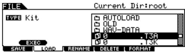
4 Press the [ENTER/STORE] button so that the Drum Kits included in the selected file are shown in the Directory/File list box.

5 Move the cursor to the desired Drum Kit then press the [SF1] EXEC button.
The Drum Kit number and name for the Load destination appear on the left half of the display.
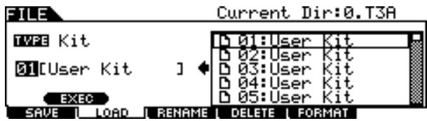
6 Select the User Drum Kit number for the Load destination.
7 Press the [SF1] EXEC button again to execute the Load operation.
Loading a Specific Song From an "All Data" or "All Song" File
You can also load a single, specific Song from the file (File extension: .T3A or .T3S) to the desired User Song number.
Press the [FILE] button to enter the File mode, then press the [F2] LOAD button to call up the Load display.
2 Move the cursor to TYPE, then set the File type to "Song."
Only available files according to the Type are listed in the Directory/File list box on the display.
3 Move the cursor to the Directory/File list box, then select the file to be loaded.
You can select any of the files listed in the Directory/File list box on the display.
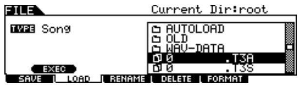
4 Press the [ENTER/STORE] button so that the Songs included in the selected file are shown in the Directory/File list box.
Empty Songs (having no data) are not shown in the Directory/ File list box.
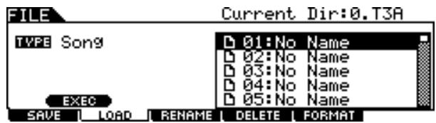
5 Move the cursor to the desired Song then press the [SF1] EXEC button.
The Song number and name for the Load destination appear on the left half of the display.
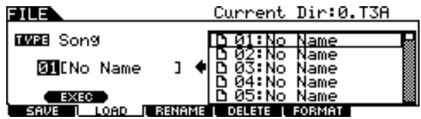
6 Select the Song number for the Load destination.
7 Press the [SF1] EXEC button again to execute the Load operation.
Loading a Specific Trigger Setup From an “All Data” or “All Trigger” File
You can also load a single, specific Trigger Setup from the file (File extension: .T3A or .T3T) to the desired Trigger Setup number.
Press the [FILE] button to enter the File mode, then press the [F2] LOAD button to call up the Load display.
2 Move the cursor to TYPE, then set the File type to "Trigger."
Only available files according to the Type are listed in the Directory/File list box on the display.
3 Move the cursor to the Directory/File list box, then select the file to be loaded.
You can select any of the files listed in the Directory/File list box on the display.
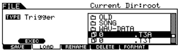
4 Press the [ENTER/STORE] button so that the Trigger Setups included in the selected file are shown in the Directory/File list box.
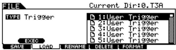
5 Move the cursor to the desired Trigger Setup as Load source then press the [SF1] EXEC button.
The Trigger Setup number and name for the Load destination appear on the left half of the display.
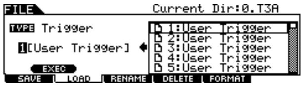
6 Select the Trigger Setup number for the Load destination.
7 Press the [SF1] EXEC button again to execute the Load operation.
Loading a Specific Chain From an "All Data" or "All Chain" File
You can also load a single, specific Chain from the file (File extension: .T3A or .T3H) to the desired Chain number.
Press the [FILE] button to enter the File mode, then press the [F2] LOAD button to call up the Load display.
2 Move the cursor to TYPE, then set the File type to "Chain."
Only available files according to the Type are listed in the Directory/File list box on the display.
3 Move the cursor to the Directory/File list box, then select the file to be loaded.
You can select any of the files listed in the Directory/File list box on the display.
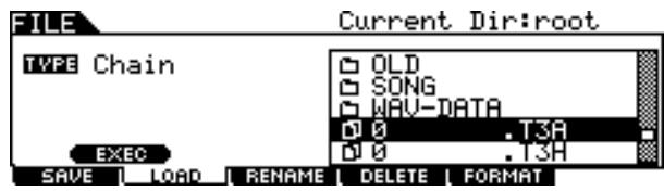
4 Press the [ENTER/STORE] button so that the Chains included in the selected file are shown in the Directory/File list box.
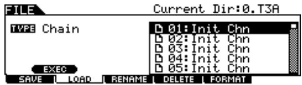
5 Move the cursor to the desired Chain as Load source then press the [SF1] EXEC button.
The Chain number and name for the Load destination appear on the left half of the display.
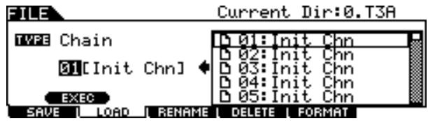
6 Select the Chain number for the Load destination.
7 Press the [SF1] EXEC button again to execute the Load operation.
Loading a Specific Voice From an "All Data" or "All Voice" File
You can also load a single, specific Voice from the file (File extension: .T3A or .T3V) to the desired User Voice number.
Press the [FILE] button to enter the File mode, then press the [F2] LOAD button to call up the Load display.
2 Move the cursor to TYPE, then set the File type to "Voice."
Only available files according to the Type are listed in the Directory/File list box on the display.
3 Move the cursor to the Directory/File list box, then select the file to be loaded.
You can select any of the files listed in the Directory/File list box on the display.

4 Press the [ENTER/STORE] button so that the Voices included in the selected file are shown in the Directory/File list box.
Empty Voices (having no audio signal) are not listed in the Directory/File list box.
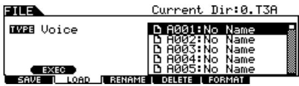
5 Move the cursor to the desired Voice as Load source then press the [SF1] EXEC button.
The Voice number and name for the Load destination appear on the left half of the display.
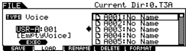
6 Select the User Voice bank and number for the Load destination.
7 Press the [SF1] EXEC button again to execute the Load operation.
Loading WAV or AIFF Audio Files to Create a User Voice
Any audio data created and edited on a computer and saved in the WAV or AIFF format can also be used as material for a User Voice on the DTX900. After connect a USB storage device containing the desired WAV/AIFF audio files then follow the instructions below.
IMPORTANT
If you are loading audio WAV/AIFF files, make sure that DIMM modules must be installed to the instrument. For details on installing DIMMs, see pages 76 and 147.
Press the [FILE] button to enter the File mode, then press the [F2] LOAD button to call up the Load display.
2 Move the cursor to TYPE, then set the File type to "Wave."
Only available files according to the Type are listed in the Directory/File list box on the display.
3 Move the cursor to the Directory/File list box, then select the file to be loaded.
You can select any of the files listed in the Directory/File list box on the display.
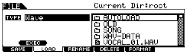
4 After selecting the file, press the [SF1] EXEC button.
The User Voice bank, number and name as Load destination appear on the left half of the display.
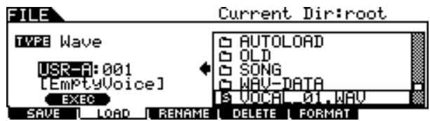
5 Select the User Voice bank and number as Load destination.
6 Press the [SF1] EXEC button again to execute the Load operation.
NOTE
- The WAV/AIFF file can be loaded is only 16bit (sample size).
- An error message appears when you try to load an unavailable file.
Loading Standard MIDI files (SMF)
A Standard MIDI file (a common file format with the file extension:“.MID” for MIDI sequence data, also called “MIDI file” or “SMF”) format 0 can be loaded from the USB storage device to the DTX900 and can be used as a User Song.
Press the [FILE] button to enter the File mode, then press the [F2] LOAD button to call up the Load display.
2 Move the cursor to TYPE, then set the File type to "Song."
Only available files according to the Type are listed in the Directory/File list box on the display.
3 Move the cursor to the Directory/File list box, then select the MIDI file (Extension:.MID) to be loaded.
You can select any of the files listed in the Directory/File list box on the display.
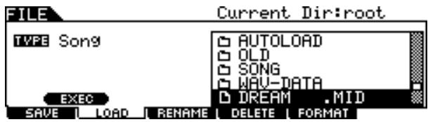
4 After selecting the MIDl file, press the [SF1] EXEC button.
The User Song number and name for the Load destination appear on the left half of the display.
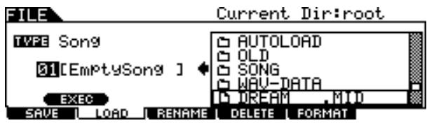
5 Select the User Song number for the Load destination.
6 Press the [SF1] EXEC button again to execute the Load operation.
NOTE
- Only Format 0 Standard MIDI Files (SMFs) can be loaded.
-
When a Standard MIDI file song (format 0) is loaded, parameters such as volume, pan, and program change located at the very top of the song (001:01:000) are handled as header data and applied to the settings on the Voice Job display called up via [SONG] [F2] JOB [SF4] VOICE. The settings on the Voice Job are not transmitted to the internal tone generator or the external MIDI device even when the Song is started although they are transmitted to the internal tone generator or the external MIDI device when the Song is selected. Because of this, the following problems may occur.
-
When a Song that includes settings such as volume, pan and program change somewhere in the middle is played back with the Repeat setting "on" (in the display called up via [SONG] [F1] PLAY, or the display called up via [SONG] [F2] JOB [SF1] SONG 03: Song Name, Tempo, Repeat) by pressing the [▶■] button, the sound originally at the top of the Song may differ in subsequent playbacks.
- When a Song that includes settings such as volume, pan and program change somewhere in the middle is played back with the Repeat setting "on" (in the display called up via [DRUM KIT] [F5] PAD [SF3] PADSONG) by using the Pad Song function (page 93), the sound originally at the top of the Song may differ in subsequent playbacks.
To avoid the problems described above, move the parameter settings at the top of the SMF Song to a few clocks later on your computer or MIDI sequencer before executing the Load operation in the File mode. These parameter settings will then not be handled as header data, meaning that they will be properly transmitted to the internal tone generator or external MIDI device when the Song is started.
Changing the Name of a File or Directory
[F3]RENAME
This lets you rename the selected file/directory selected on the current drive.
You can rename files using up to eight alphabetic and numeric characters. Files having the same name cannot be saved in the same directory.
Files are named according to MS-DOS naming conventions. If the file name contains spaces and other characters unrecogn- nized in MS-DOS, these characters will automatically be replaced by "_" (underscore) characters when saving.
Press the [FILE] button to enter the File mode then press the [F3] RENAME button to call up the Rename display.
![YAMAHA DTX-900 - Press the [FILE] button to enter the File mode then press the [F3] RENAME button to call up the Rename display. - 1](/content/2025/01/114986/images/9909c990b11650b2c550ec7a4a4eff72aa122505675231993de84231f1553129.jpg)
① TYPE
Determines the desired File type. For details about the File type, see page 113.
② File /Directory (Folder) selection box
Indicates the directories and files in the current Directory. In this box, the directories and files are listed in alphabetical order. Pressing the [ENTER/STORE] button enters the selected directory (folder) while pressing the [EXIT] button returns to the next highest directory.
You can distinguish the directory and file by the indicator at left end of each line.
![YAMAHA DTX-900 - Press the [FILE] button to enter the File mode then press the [F3] RENAME button to call up the Rename display. - 2](/content/2025/01/114986/images/4b498f0178298382383899f470cbeeef9652502710333d6e2638d1c439f27256.jpg)
............ Directory (Folder)
![YAMAHA DTX-900 - Press the [FILE] button to enter the File mode then press the [F3] RENAME button to call up the Rename display. - 3](/content/2025/01/114986/images/cbe7f1f8af7ab71ef853b84568a1b3661ee5dca5b643c34358e11717380b2f3b.jpg)
......File
③ File name input location
You can enter a name of up to eight characters for the file you are about to save. For detailed instructions on naming, refer to "Basic Operation" on page 15.
(4) [SF1] EXEC
Pressing this button executes the rename of selected file.
⑤ [SF2] SET NAME
Pressing this button copies the file/directory name selected at the file/directory selection box to the file name input location.
6 [F6] NEW
Pressing this button creates a new directory in the current directory.
2 Move the cursor to TYPE, then set the desired file type by using the data dial, or the [INC/YES] and [DEC/NO] buttons.
3 Move the cursor to the file/directory selection box, then select the desired file or directory to be renamed by using the data dial, or the [INC/YES] and [DEC/NO] buttons.
4 Press the [SF2] SET NAME button.
The name of the selected file is copied to the file name input location.
5 Enter the new name.
Follow the instructions for "Inputting Characters (Naming, etc.)" on page 15. You can call up the Character List by pressing the [SF6] button.
![YAMAHA DTX-900 - Press the [FILE] button to enter the File mode then press the [F3] RENAME button to call up the Rename display. - 4](/content/2025/01/114986/images/46a80e81138221fe16db0f601ff9b515cd882efcee2d981031d3984610a034aa.jpg)
6 Press the [SF1] EXEC button to execute the Rename operation.
Deleting a File or Directory
[F4] DELETE
Press the [FILE] button to enter the File mode, then press the [F4] DELETE button to call up the Delete display.
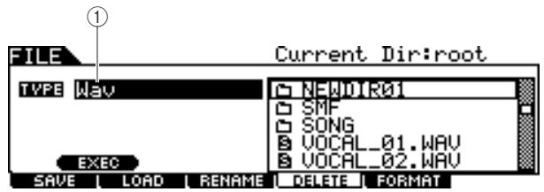
① TYPE
Determines the desired File type. For details about File types, see page 113.
2 Move the cursor to TYPE, then select the File Type to which the file to be deleted belongs.
For details about the File type, see page 113.
3 Move the cursor to the Directory/File list box, then select the file to be deleted.
4 Press the [SF1] EXEC button.
A confirmation message will appear. Press the [DEC/NO] or [EXIT] button to cancel the Delete operation.
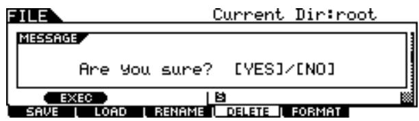
Press the [INC/YES] button to execute the Delete operation.
NOTE
- When you wish to delete a directory, delete all the files and folders contained in the directory beforehand. Please keep in mind that only directories that contain no files or other nested folders can be deleted.
Formatting USB Storage Media
[F5] FORMAT
Before you can use a new USB storage device with this instrument, you will need to format it. Follow the instructions below.
NOTICE
- Make sure there is no important data in the USB storage device before formatting; otherwise all data will be deleted.
NOTE
- You can also format the USB storage device on the computer; however, for best results and to avoid load save errors, always use USB storage devices that have been formatted on the DTX900.
1 Connect a USB storage device to the USB TO DEVICE terminal.
2 Press the [FILE] button to enter the File mode, then press the [F5] FORMAT button to call up the Format display.
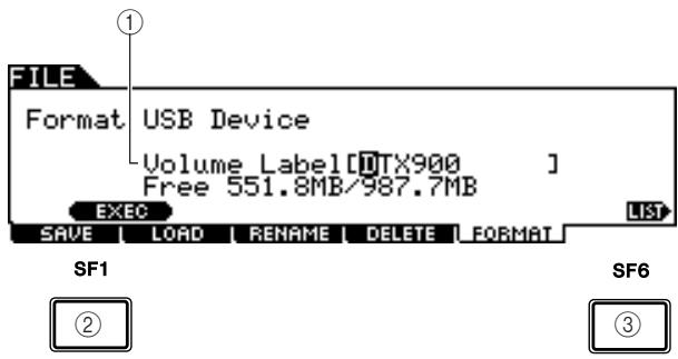
① Volume Label
Determines the name of the Volume Label. The Volume Label is the name assigned to the USB storage device. The Volume Label can contain up to 11 characters. For detailed instructions on naming, refer to "Basic Operation" on page 15.
② [SF1] EXEC
Pressing this button executes the Format operation.
③ [SF6] LIST
You can call up the Character List by pressing this button. Refer to "Using the character list," page 15, for more information on name entry.
3 Enter the name of the Volume Label as desired.
4 Press the [SF1] EXEC button. (The display prompts you for confirmation.)
Press the [DEC/NO] button to cancel the Format.
Press the [INC/YES] button to execute the Format.
NOTE
- The format operation erases all data from the target memory device and automatically creates an "AUTOLOAD" directory, see page 125.
This chapter explains the Utility mode called up via the [UTILITY] button.
In the Utility mode, you can set parameters that apply to the entire system of the DTX900.
Basic Procedure in the Utility Mode
Press the [UTILITY] button to enter the Utility mode.

2 Note the tab menus (corresponding to the [F1] – [F6] and [SF1] – [SF5] buttons) to find the desired function, then press the relevant button to call up the desired display.
3 Move the cursor to each parameter, then set the value by using the data dial, or the [INC/YES] and [DEC/NO] buttons.
4 After setting, press the [ENTER/STORE] button to store the Utility settings.
NOTICE
- All Utility settings will be lost if the power is turned off without storing.
General Settings
[F1] GENERAL
Tone Generator Settings
[SF1] TG
From this display, you can make overall settings for the internal tone generator. The settings here only affect the internal tone generator block. The MIDI output will not be affected.
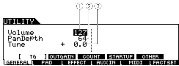
① Volume
Determines the overall volume for the tone generator. The lower the value, the lower the actual volume will be when setting the slider on the front panel to maximum.
Settings 0-127
② Pan Depth
Determines the pan depth (the left and right stereo spread), maintaining the current pan balance between various parts.
| Settings | 1 – 127 |
③ Tune
Determines the fine tuning of the overall sound. You can adjust the tuning in cent increments.
Settings -102.4-0-+102.3
Output Gain Settings of the Output Jacks
[SF2] OUTGAIN
From this display, you can set the output gain for individual Output jacks. The higher the value, the louder the actual volume of the sound output via the specified Output jack.
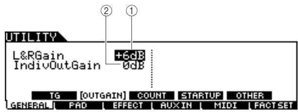
① L&RGain
Determines the output gain of the OUTPUT L/MONO, R and PHONES jacks.
Settings 0dB, +6dB
② IndivOutGain
Determines the output gain of the INDIVIDUAL OUTPUT jacks. The setting here is applied to all the INDIVIDUAL OUTPUT jacks.
Settings 0dB, +6dB
Count Settings
[SF3] COUNT
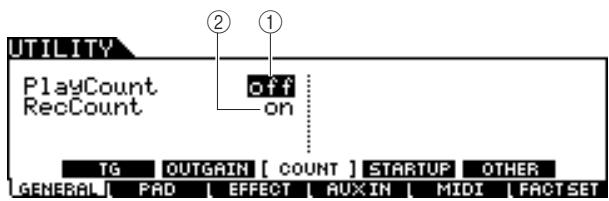
① Play Count
Enables or disables a two-measure lead-in click count before actual song playback, after you press the [/] button.
Settings off, on
② RecCount
Enables or disables a two-measure lead-in click count before actual song recording, after you press the [ / ] button.
Settings off, on
Initial Settings Called Up When Turning the Power On
[SF4] STARTUP
From this display, you can set the Drum Kit number, Song number and Trigger Setup number called up automatically every time you turn the power on.
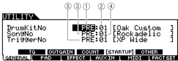
① Drum Kit Bank
Determines the Drum Kit Bank that is called up automatically every time you turn the power on.
| Settings | PRE, USR, EXT-A - EXT-P |
② Drum Kit No
Determines the Drum Kit number of the Drum Kit Bank specified above that is called up automatically every time you turn the power on.
| Range | 01 – 50 (01 – 99 when EXT is selected) |
③ Song Bank
Determines the Song Bank that is called up automatically every time you turn the power on.
| Settings | PRE, USR, EXT |
④ Song No
Determines the Song number of the Bank specified above that is called up automatically every time you turn the power on.
| Range | 01 - 99 |
⑤ Trigger No
Determines the Trigger Setup number that is called up automatically every time you turn the power on.
Settings PRE:01-USR:05
Other Settings
[SF5]OTHER
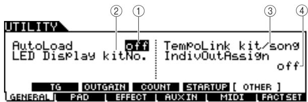
① AutoLoad
Determines whether the Auto Load function is on or off. When this is on, the instrument will automatically load the files in the AUTOLOAD directory (from the USB storage device) to User memory - whenever the power is turned on. When you use the Auto Load function, you must put the files of "AllData," "Utility," "Click," "AllTrigger," "AllKit," "AllChain," "AllSong," and "AllVoice" in the AUTOLOAD directory. You can put only one file for each type in the AUTOLOAD directory. When an "AllData" file exists in the AUTOLOAD directory, only the "AllData" file will be loaded, and other files will not be loaded.
| Settings | off, on |
② LED Display
Determines the information which is indicated on the LED display. When "KitNo" is selected, the current Drum Kit number is indicated on the LED display. When "tempo" is selected, the current tempo value is indicated on the LED display. When "mode" is selected, the program number of the current mode (Drum Kit number in the Drum Kit mode, Song number in the Song mode, Trigger Setup number in the Trigger mode, Step number in the Chain mode and User Voice number in the Sampling mode) is indicated on the LED display.
| Settings | kitNo., tempo, mode |
③ Tempo Link
When this parameter is set to "kit/song," changing the Drum Kit or Song will change the tempo value according to the setting of the new Drum Kit or Song. When this parameter is set to "off," changing the Drum Kit or Song will maintain the tempo value even if the new Drum Kit or Song has the tempo value setting. Normally, set this to "kit/song."
| Settings | off, kit/song |
④ IndivOutAssign
Determines the specific outputs for each part.
off: Each part will be output according to the OutputSel parameter called up via [DRUM KIT] [VOICE] [OUTTUNE].
6paraOut/8paraOut: Each part will be output as follows.
| Part | ||
| Output Jack | 6paraOut | 8paraOut |
| indiv1 | KICK | |
| indiv2 | SNARE | |
| indiv3 | TOM (Left) | |
| indiv4 | TOM (Right) | |
| indiv5 | CYMBAL/HI-HAT/MISC (Left) | HI-HAT |
| indiv6 | CYMBAL/HI-HAT/MISC (Right) | MISC |
| OUTPUT L/MONO | — | CYMBAL (Left) |
| OUTPUT R | — | CYMBAL (Right) |
| Settings | off, 6paraOut, 8paraOut |
NOTE
- If you select a setting other than "off," Normal voices on MIDI channels other than channel 10 will be output to the OUTPUT L/MONO and R connectors as well as the PHONES jack.
Pad Settings
[F2] PAD
Hi-Hat Settings
[SF1] HI HAT
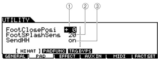
① FootClosePosi (Foot Close Position)
Determines the amount of time it takes to detect a foot splash (from the start of a downward press to the opening of the hi-hat controller). The smaller the value, the more narrow the "virtual" open position is.
| Range | -32 – +32 |
② FootSplashSens (Foot Splash Sensitivity)
Determines the length of time from the moment you apply a foot-splash performance to the Hi-Hat Controller to the moment the foot-splashed hi-hat sound is actually triggered. For larger values, you can play the foot-splashed sound more easily; however, slight movements of the pedal may trigger the sound inadvertently. It is a good idea to set this parameter to "off" if you do not play foot-splashes.
| Range | off, 1 – 127 |
③ SendHH
Determines whether or not the continuous change of the sound generated by opening/closing the Hi-Hit cymbal (by pressing/releasing the Hi-Hat Controller) is transmitted as MIDI messages via MIDI OUT.
| Settings | off, on |
Pad Function Settings
[SF2] PADFUNC
From this display, you can assign functions other than triggering the drum sound to the pad (Trigger Input Source).
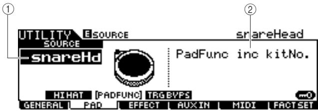
① SOURCE (Trigger Input source)
Determines the Trigger Input Source to which the specified function is assigned. When Input Lock (page 79) is turned off, you can select the Trigger Input Source also by hitting the corresponding section of the pad.
| Settings | Refer to the trigger input Source List on page 61. |
NOTE
- The Pad Function setting overcomes the Pad Song setting (page 93) if both of them are assigned to the same Trigger Input Source.
② PadFunc
Determines the function assigned to the Trigger Input Source specified above.
Settings
See below.
Off No function is assigned. Normal operation.
inc kitNo. Hitting the pad increases the Drum Kit number by 1.
dec kitNo. Hitting the pad decreases the Drum Kit number by 1.
inc chain Hitting the pad increases the Chain Step number by 1.
dec chain Hitting the pad decreases the Chain Step number by 1.
inc tempo Hitting the pad increases the value of the tempo by 1.
dec tempo Hitting the pad decreases the value of the tempo by 1.
tap tempo Hitting the pad three times sets the tempo value even when the Tap display is not called up.
clk on/off Hitting the pad starts/stops Click playback.
Trigger Bypass Settings
[SF3]TRGBYPS
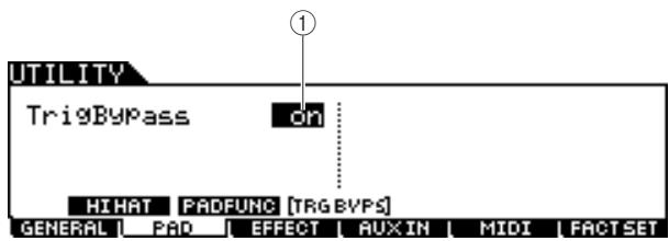
① TrigBypass
When this parameter is set to on, the DTX900 will not accept any Trigger Signals coming from all Trigger Input Sources. This parameter is useful when you want to cancel all Trigger Signals temporarily in order to change the pad connection setup. This parameter should be set to off normally.
Settings
off, on
Effect Settings
[F3] EFFECT
Among the entire Effect system (page 68) of the DTX900, the parameters related to the Master EQ and Master Effect can be set in the Utility mode.
NOTE
For details about the Effect structure of the DTX900, see page 68.
Master EQ Settings
[SF1] MEQ
From this display you can apply five-band equalization to the entire sound of the DTX900.
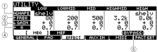
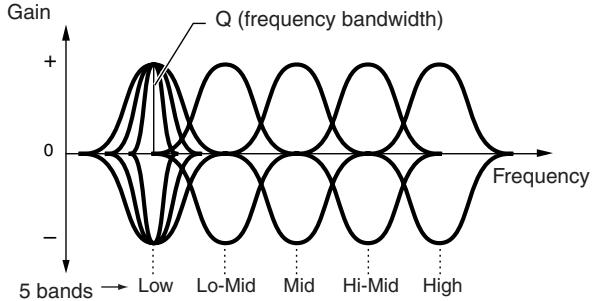
① SHAPE
Determines whether the equalizer type used is Shelving or Peaking. The Peaking type attenuates/boosts the signal at the specified Frequency setting, whereas the Shelving type attenuates/boosts the signal at frequencies above or below the specified Frequency setting. This parameter is available only for the LOW and HIGH frequency bands.
| Settings | shelv (Shelving type), peak (Peaking type) |
shelv (Shelving type)
This type of EQ shape lets you attenuate/boost the signal at frequencies above or below the specified Frequency setting.
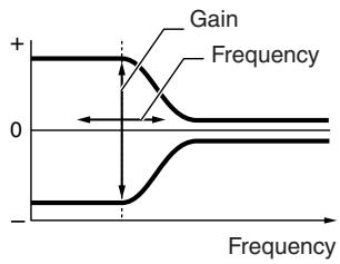
EQ Low
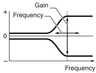
EQ High
- peak (Peaking type)
This type of EQ shape lets you attenuate/boost the signal at the specified Frequency setting.
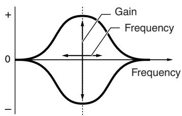
② FREQ (Frequency)
Determines the center frequency. Frequencies around this point are attenuated/boosted by the Gain setting.
| Range | See below. |
| LOW | When the Shape is set to “shelv”:32Hz – 2.0kHzWhen the Shape is set to “peak”:63Hz – 2.0kHz |
| LOWMID, MID, HIGHMID100Hz – 10kHz | |
| HIGH | 500Hz – 16kHz |
③ GAIN
Determines the level gain for the Frequency (set above), or the amount the selected frequency band is attenuated or boosted.
| Range | -12 dB – +0 dB – +12 dB |
④ Q (frequency bandwidth)
This varies the signal level at the Frequency setting to create various frequency curve characteristics. The higher the setting, the smaller the Q (Bandwidth). The lower the setting, the greater the Q (Bandwidth).
| Range | 0.1 – 12.0 |
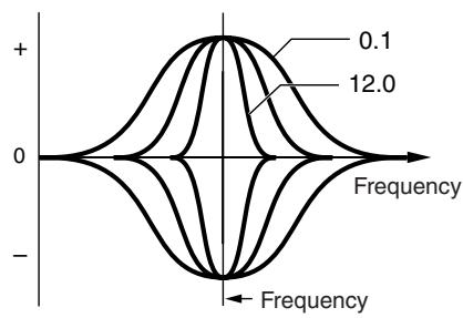
⑤ [SF5] BYPASS
Pressing this button toggles the bypass status of the Master EQ between on and off. When Bypass is turned off (BYPASS is shown with white text in black), the Master EQ will be applied to the entire sound of the DTX900. When Bypass is turned on (BYPASS is shown with black text in white), the Master EQ will be bypassed for the entire sound of the DTX900.
Master Effect Settings
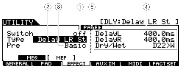
[SF2] MEF
① Switch
Determines whether Master Effect is applied or not to the entire sound of the DTX900.
| Settings | off, on |
② Type
Determines the Master Effect type.
| Settings | Details about the Effect types are described on page 70. |
(3) Pre
You can set various parameters in order to change how the sound is affected by the selected Effect type. This parameter lets you call up the pre-programmed settings of these effect parameters. Data List booklet for information on the parameters for each Effect preset.
④ Effect parameter
The number of parameters and values available differs depending on the currently selected effect type. Refer to page 72 for details about the Effect parameters. Refer to the separate Data List booklet for information on the parameters for each Effect type.
(5) PAGE
This appears when another page can be called up from the current page. Use the Cursor [> or [ ] button to call up another page.
External Audio Settings
[F4] AUXIN
You can set parameters related to audio signals input via the AUX IN/SAMPLING IN jack.
Output Settings
From this display, you can set parameters such as volume and pan of the audio signals input via the AUX IN/SAMPLING IN jack. These parameters are useful, for example, when playing or practicing along with a CD or other source connected to the AUX IN/SAMPLING IN jack.
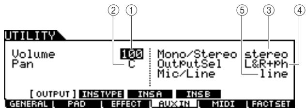
[SF1] OUTPUT
① Volume
Determines the output level of the audio signals input via the AUX IN/SAMPLING IN jack.
| Range | 0 – 127 |
② Pan
Determines the stereo pan position of the audio signals input via the AUX IN/SAMPLING IN jack.
| Range | L63 (far left) – C (center) – R63 (far right) |
③ Mono/Stereo
Determines the signal configuration for the audio signals input via the AUX IN/SAMPLING IN jack, or how the signal or signals are routed (stereo or mono).
| Settings | L mono, R mono, L+Rmono, stereo |
L mono Only the L channel of the audio input is used.
R mono Only the R channel of the audio input is used.
L+Rmono The L and R channels of the audio input are mixed and processed in mono.
Stereo Both the L and R channels of the audio input are used.
④ OutputSel
Determines the output jack assignment for the audio signals input via the AUX IN/SAMPLING IN jack.
| Settings | See the table below. |
| LCD | Output jacks | Stereo/Mono |
| L&R+ph | OUTPUT L/R and PHONES | Stereo |
| Phones | PHONES | Stereo |
| L&R | OUTPUT L/R | Stereo |
| Ind1&2 | INDIVIDUAL OUTPUT 1 and 2 | Stereo (1: L, 2: R) |
| Ind3&4 | INDIVIDUAL OUTPUT 3 and 4 | Stereo (3: L, 4: R) |
| Ind5&6 | INDIVIDUAL OUTPUT 5 and 6 | Stereo (5: L, 6: R) |
| Ind1 | INDIVIDUAL OUTPUT 1 | Mono |
| : | : | : |
| Ind6 | INDIVIDUAL OUTPUT 6 | Mono |
⑤ Mic/Line
When using the AUX IN/SAMPLING IN jacks, this determines the input source, microphone (mic) or line.
| Settings | mic, line |
Intended for low output equipment, such as a microphone, electric guitar or bass.
line Intended for high output equipment, such as a keyboard, synthesizer, or CD player.
Insertion Effect Connection Settings
[SF2] INSTYPE
From this display, you can set the parameters related to the Insertion Effect Types applied to audio signals input via the AUX IN/SAMPLING IN jack.
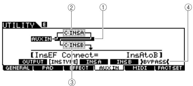
NOTE
For details about the Effect structure of the DTX900, see page 68.
① InsConnect
Determines the effect routing for Insertion Effects A and B. The setting changes are shown on the diagram in the display, giving you a clear picture of how the signal is routed.
Settings
Ins A to B, Ins B to A
Ins A to B Signals processed with Insertion Effect A will be sent to Insertion Effect B.
Ins B to A Signals processed with Insertion Effect B will be sent to Insertion Effect A.
② Insertion A (Insertion A Category/Type)
③ Insertion B (Insertion B Category/Type)
Determines the Insertion Effect A/B type after selecting a category. From the Category column, you can select one of the Effect Categories, each of which contains similar Effect types. From the Type column, you can select one of the Effect Types listed in the selected Category.
Settings
Details about the Effect categories are described on page 70.
④ [SF5] BYPASS
Pressing this button toggles the bypass status of the Insertion Effect between on and off. When Bypass is turned off (BYPASS is shown with white text in black), the Insertion Effect will be applied to the audio signals input via the AUX IN/SAMPLING IN jack. When Bypass is turned on (BYPASS is shown with black text in white), the Insertion Effect will be bypassed for the audio signals input via the AUX IN/SAMPLING IN jack.
Insertion Effect Type Settings
[SF3] Ins A, [SF4] Ins B
From these displays, you can set the Insertion Effect Types applied to the audio signals input via the AUX IN/SAMPLING IN jack.
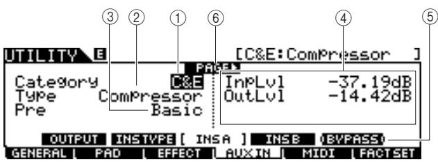
① Category
② Type
From the Category column, you can select one of the Effect Categories, each of which contains similar Effect types. From the Type column, you can select one of the Effect Types listed in the selected Category.
| Settings | Details about the Effect categories are described on page 70. |
③ Pre
You can set various parameters in order to change how the sound is affected by the selected Effect type. This parameter lets you call up the pre-programmed settings of these effect parameters.
④ Effect parameters
The number of parameters and values available differs depending on the currently selected effect type. Refer to page 72 for details about the Effect parameters. Refer to the separate Data List booklet for information on the parameters for each Effect type.
⑤ [SF5] BYPASS
Pressing this button toggles the bypass status of the Insertion Effect between on and off. When Bypass is turned off (BYPASS is shown with white text in black), the Insertion Effect will be applied to the audio signals input via the AUX IN/SAMPLING IN jack. When Bypass is turned on (BYPASS is shown with black text in white), the Insertion Effect will be bypassed for the audio signals input via the AUX IN/SAMPLING IN jack.
(6) PAGE
This appears when another page can be called up from the current page. Use the Cursor [>] or [<] button to call up another page.
MIDI Settings
[F5]MIDI
From these displays called up via the [F5] MIDI button, you can set the MIDI related parameters. The tone generator block of the DTX900 can handle MIDI messages on 16 channels simultaneously. Among these channels, MIDI channel 10 is used to handle the Drum Voices triggered by hitting the pads.
Setting Program Change Reception On/Off
[SF1] SWITCH
The tone generator block of the DTX900 can play various types of Voices as well as Drum Voices by receiving Program Change messages over MIDI channels other than 10. The related parameters can be set from this display.
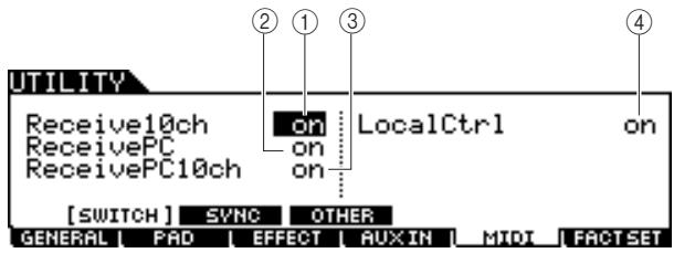
① Receive10ch
Determines whether or not the DTX900 receives MIDI channel messages over channel 10 from the external MIDI device. When set to on, the DTX900 will receive messages over MIDI channel 10. When set to off, the DTX900 will ignore them, meaning that the sound of the DTX900 will be triggered only by hitting the connected pad or pressing the Audition button.
Settings
off, on
NOTE
- MIDI channel messages include Note on/off, Program Change, Control Change, Pitch Bend Change, and so on.
② ReceivePC
Determines whether or not the DTX900 receives Program Change messages from an external MIDI device. When set to on, the DTX900 will receive Program Change messages from the external MIDI device. When set to off, the DTX900 will ignore them.
Settings
off, on
③ ReceivePC10ch
Determines whether or not the DTX900 receives Program Change messages over MIDI channel 10 (which handles the part of the Drum Voice triggered by hitting the pads). If you want to change the Drum Kit number from the external MIDI device, this parameter should be set to on. Keep in mind that this parameter is effective only when the Receive PC parameter ② is set to on.
Settings
off, on
④ LocalCtrl (Local Control)
This determines whether or not the tone generator of the instrument responds to your pad playing. Normally, this should be set to "on" - since you'll want to hear the sound of the DTX900 as you play it. When this parameter is set to "off," no sound is produced even if you hit the pads, but the corresponding MIDI messages will be transmitted via MIDI. Also, the internal tone generator block will respond to messages received via MIDI. You may want to set this to "off" when you are recording your drum performance as MIDI data to another device, such as a sequencer or DAW.
Settings
off, on
MIDI Sync Settings
[SF2]SYNC
Song or Click playback of the DTX900 can be synchronized with the external MIDI clock coming from the MIDI device connected to the DTX900. (Song or Click conventionally plays according to the internal clock.) From this display, the related parameters can be set.
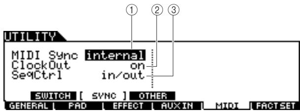
① MIDI Sync
Determines whether Song playback will be synchronized to the instrument's internal clock or an external MIDI clock.
| Settings | internal, MIDI |
| Internal | Synchronization to internal clock. Use this setting when this instrument is to be used alone or as the master clock source for other equipment. |
| MIDI | MIDI Synchronization to a MIDI clock received from an external MIDI instrument via MIDI. |
NOTE
- When the MIDI Sync parameter is set to MIDI, make sure that the external MIDI equipment or computer connected to the DTX900 can transmit MIDI clock data.
② ClockOut
Determines whether MIDI clock (F8H) messages will be transmitted from the DTX900 via MIDI.
| Settings | off, on |
③ SeqCtrl
Determines whether Sequencer Control signals – start (FAH), continue (FBH), and stop (FCH) – will be received and/or transmitted via the MIDI OUT/USB terminal.
| Settings | off, in, out, in/out |
| off | Not transmitted/recognized. |
| In | Recognized but not transmitted. |
| out | Transmitted but not recognized. |
| in/out | Transmitted/recognized. |
MIDI Other Settings
[SF3]OTHER
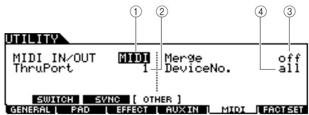
① MIDI IN/OUT
Determines which physical output/input terminal(s) will be used for transmitting/receiving MIDI data.
| Settings | MIDI, USB |
(2) ThruPort
When using the USB terminal for MIDI transmission/reception, you can have the DTX900 respond to MIDI data over one port, while relaying the data for another port number (which can be set here) to a separate tone generator (connected to the MIDI OUT terminal).
| Settings | 1, 2 |
③ Merge
This parameter allows you to mix incoming MIDI data (received via MIDI IN) with MIDI data generated on the DTX900, and output them together from MIDI OUT. Merge is enabled when this is set to on. This parameter is useful when you want to control a MIDI tone generator connected to the DTX900 by playing a different MIDI keyboard connected to the DTX900 and playing the drum pads at the same time.
| Settings | off, on |
④ DeviceNo.
Determines the device number used by the DTX900 in receiving or transmitting data. This number must match the device number of the external MIDI device when transmitting/ receiving bulk data, parameter changes or other system exclusive messages.
| Settings | 1 – 16, all, off |
| all | When this is selected, system exclusive messages for all MIDI device numbers are received. The DTX900 is recognized as Device Number 1. |
| off | When this is selected, system exclusive messages such as bulk dump and parameter change cannot be transmitted or received. When you try to execute transmission or reception of system exclusive messages, an error message appears. |
Resetting the User Memory to the Initial Factory Settings
[F6] FACTSET
The original factory settings of the DTX900's User Memory (page 76) can be restored. For details and instructions, see page 23.
Chain Mode
[CHAIN]
This chapter explains the Chain mode called up via the [CHAIN] button.
In the Chain mode, you can program Chains, each consisting of up to 64 Steps and each of which has its own Drum Kit number, Song number or Click settings (only tempo and time signature). Each Step of the programmed Chain can be called up in order one by one by selecting a Step number in the [F1] SELECT display in the Chain mode or hitting the pad to which the "inc chain" or "dec chain" operation is assigned as the Pad Function (page 126) in the Utility mode. By using the Chain feature, for example, you can arrange different Drum Kits to be selected in your desired order to match your live performance, or you can arrange the different Songs to be selected in order of difficulty to suit your practice needs.
The DTX900 can memorize up to 64 Chains for recalling them instantly recall whenever you want.
Using a Programmed Chain
[F1] SELECT
From this display, you can use a Chain programmed from the [F2] EDIT display, and call up Steps in the Chain one by one.
Press the [CHAIN] button to enter the Chain mode.
2 Press the [F1] SELECT button to call up the Chain Select display.
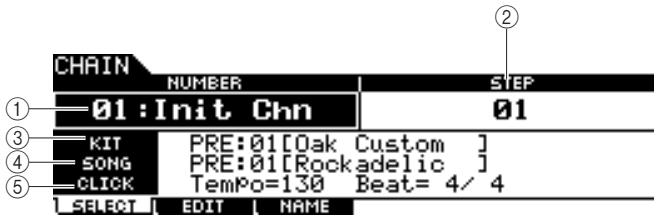
① NUMBER (Chain number)
Determines the Chain number.
| Settings | 01 – 64 |
② STEP
Determines the Step number of the selected Chain.
| Settings | 01 - 64 |
③ KIT
Indicates the currently specified Drum Kit number and name.
④ SONG
Indicates the currently specified Song number and name.
⑤ Click
Indicates the currently specified tempo and time signature.
3 Move the cursor to the Chain number, then select the desired Chain by using the data dial, or the [INC/YES] and [DEC/NO] buttons.
Selecting the Chain number calls up the settings programmed for Step 01.
4 Use the selected Chain program.
- To start/stop the Song or Click programmed in each Step:
Each Step of the Chain does not start a Song or Click, but simply calls up the specified Drum Kit, Song number or Click settings. Pressing the [▶/■] button starts/stops the Song while pressing the [CLICK ON/OFF] button to starts/stops the Click.
- To change the Step number:
Two methods are available.
You can change the Step number from the [F1] SELECT display by moving the cursor to STEP, then using the data dial, [INC/YES] and [DEC/NO] buttons. This method is available only in the Chain mode.
You can change the Step number also by hitting the pad to which "inc chain" or "dec chain" has been assigned as the Pad Function (in the display called up via the [UTILITY] [F2] PAD [SF2] PAD FUNC.) This method is available in any mode. It is a good idea to use this method when you want to change the Chain Step number quickly as you perform.
NOTE
- If you select a Step to which JUMP is assigned, the Step switches to the specified different Chain number.
- If you select a Step which is grouped with other different Steps, all settings of the grouped Steps are called up simultaneously.
Programming a Chain
[F2] EDIT
From this display, you can program a Chain by setting the parameters for each Step.
In the Chain Select display, move the cursor to the chain number, then select the desired Chain number by using the data dial, [INC/YES] and [DEC/NO] buttons.
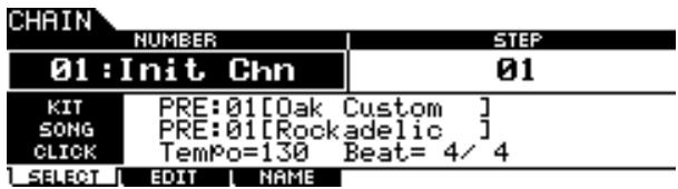
2 Press the [F2] EDIT button to call up the Chain Edit display.
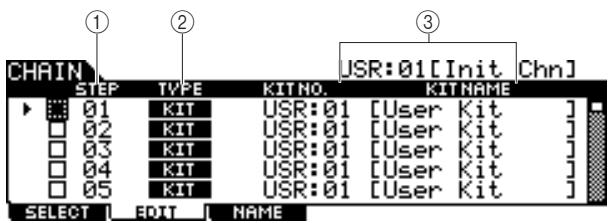
① STEP
Indicates the Step number. You can use the checkbox when you want to group a few Steps together. For details about Step Grouping, see page 134.
NOTE
- Keep in mind that only the checkbox of Step 1 cannot be entered.
② TYPE
Determines the type of data called up when the corresponding Step is selected. Selecting "KIT" or "SONG" calls up the respective Drum Kit number or Song number shown at right. Selecting "CLICK" calls up the tempo and time signature (BEAT) shown at right. When "JUMP" is selected, the Chain sequence switches to the Chain number shown at right. When "END" is selected, the Chain program ends when the corresponding Step is selected.
Settings KIT (Drum Kit), SONG, CLICK, JUMP, END
③ KIT NO./ SONG NO./ TEMPO and BEAT/CHAIN NO.
The indication of this column differs depending on the selected TYPE. When TYPE is set to "KIT," this column determines the Drum Kit number called up when the corresponding Step is selected. When TYPE is set to "SONG," this column determines the Song number called up when the corresponding Step is selected. When TYPE is set to "CLICK," this column determines the tempo and time signature called up when the corresponding Step is selected. When TYPE is set to "JUMP," this column determines the Chain number called up when the corresponding Step is selected.
3 Program the Chain.
- Setting the parameters for each Step
Move the cursor to Step 01, then set the desired TYPE by using the data dial, [INC/YES] and [DEC/NO] buttons. When setting TYPE to "KIT," move the cursor and select the desired Drum Kit bank and number. When setting TYPE to "SONG," select the desired Song number. When setting TYPE to "CLICK," select the desired tempo and time signature (BEAT). When setting TYPE to "JUMP," select the desired Chain number. In the same manner, continue making settings for the rest of the steps as desired.
- Step Grouping
If you want to call up multiple Steps simultaneously (for example, if you want to call up a specific Drum Kit number and Song number simultaneously), you can use the Step Grouping function by entering checkmarks to the appropriate boxes at the left of the Step number. For details, see below.
- Jumping to a different Chain
Each Chain can contain up to 64 Steps. However, if you want to make more than 64 Steps, you can use the Jump function which allows you link the currently edited Chain to a different Chain. Set the TYPE to "JUMP" then set the desired Chain number for the Jump destination in the right column.
4 After making the desired Step settings, move the cursor to the Step just after the last Step programmed, then set TYPE to END.
This operation is necessary in order to avoid calling up unnecessary Steps. When "END" is assigned to a step, no Step numbers following the END step can be selected.
Press the [ENTER/STORE] button after completing the Chain.
The following display appears.
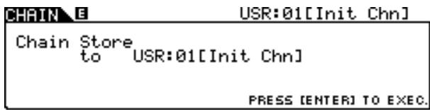
6 Select the Chain number for the destination by using the [INC/YES], [DEC/NO] buttons and data dial.
7 Press the [ENTER/STORE] button.
The display prompts you for confirmation. To cancel the Store operation, press the [DEC/NO] button.
![YAMAHA DTX-900 - Press the [ENTER/STORE] button. - 1](/content/2025/01/114986/images/cb37404c49232bf9ad92cb3184abc7ff960d2124abed3bb46d2cd2787fffc3a7.jpg)
Press the [INC/YES] button to execute the Store operation.
NOTICE
- The edited Chain will be lost when selecting a different Chain or turning the power off. Make sure to store the Chain data to internal memory by pressing the [ENTER/STORE] button before selecting a different Chain or turning the power off.
- Never attempt to turn off the power while the message "Please keep power on" is shown. All Chain data may be lost.
Step Grouping
This feature is useful when you want to call up multiple Steps simultaneously (for example, calling up the Drum Kit number and tempo simultaneously). In the [F2] EDIT display in the Chain mode, enter the checkmark(s) to the checkbox(es) at left of the Step number(s) following the first Step number of the group.
Example 1)
The Steps below are called up via 01 02 03 04 05 in order.
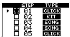
Example 2)
The Steps below are called up via 01 and 02 03 and 04 05 in order.
The settings of Steps 01 and 02 are called up simultaneously when this Chain is selected. Selecting the next Step (Step 03) calls up the settings of Steps 03 and 04, then selecting the next Step calls up the settings of Step 05.
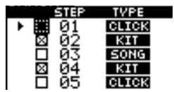
Example 3)
The Steps below are called up via 01 02 , 03 and 04 05 .
The settings of the Steps 01 are called up when this Chain is selected. Selecting the next Step calls up the settings of Steps 02 - 04 simultaneously.
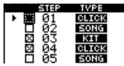
Naming the Created Chain
[F3] NAME
From this display, you can enter the desired name for the current Chain (up to eight characters).
After the Chain programming is completed, press the [F3] NAME button.
2 Enter a name for the current Chain.
For detailed instructions on naming, refer to "Basic Operation" on page 15.
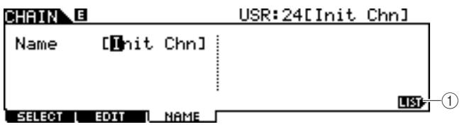
① [SF6] LIST
You can call up the Character List by pressing this button. Refer to "Using the character list," page 15, for more information on name entry.
3 Press the [ENTER/STORE] button after making the settings.
4 Select the Chain number for the destination by using the [INC/YES], [DEC/NO] buttons and data dial.
5 Press the [ENTER/STORE] button.
The display prompts you for confirmation. To cancel the Store operation, press the [DEC/NO] button.
6 Press the [INC/YES] button to execute the Store operation.
Sampling Mode
[ SAMPLING]
The Sampling Record function lets you record sounds—such as vocals from a connected microphone, the signal from an electric guitar, or audio from an external CD or MP3 player—directly to the DTX900, and assign them to the DTX900 as User Drum Voices. The User Drum Voices obtained via the Sampling function can be assigned to the Drum Kit and played back by hitting the pads.
IMPORTANT
In order to use the Sampling function, DIMM modules must be installed to the DTX900. When no DIMMs are installed to the DTX900, you cannot enter the Sampling mode even if you press the [SAM-PLING] button. For details on installing DIMMs, see page 147.
User Voice
In addition to Preset Voices, the DTX900 has User Voices, which you can create in the following ways: Recording audio signals in the Sampling mode or loading WAV files or AIFF files from the USB storage device connected to the DTX900 in the File mode.
Sampling Setup
1 Turn the power off and set the GAIN knob on the rear panel to the minimum.
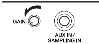
NOTE
- For details about how to turn the power on/off, see page 18.
2 Connect an audio device (CD player, etc.) to the AUX IN/SAMPLING IN jack on the rear panel.
3 Turn the power of the DTX900 on.
4 Press the [UTILITY] button to enter the Utility mode, press the [F4] AUXIN button, then press the [SF1] OUTPUT button to call up the Output display.
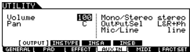
5 Set the Mic/Line parameter.
When connecting low output equipment, such as a microphone, electric guitar or bass, set the Mic/Line parameter to "mic." When connecting high output equipment, such as a keyboard, synthesizer or CD player, set the Mic/Line parameter to "line."
6 Press the [ENTER/STORE] button to store these settings.
Sampling Operation and User Voice Assignment
[F1] SELECT/[F2] SETTING
This section describes the instructions on executing the Sampling operation and creating a User Voice. The created User Voice can be assigned to the Drum Kit and played back by hitting the pad.
1 Connect a microphone or audio equipment to the DTX900.
2 Press the [DRUM KIT] button, and then select the Drum Kit to which you want to assign the User Voice.
3 Press the [SAMPLING] button to enter the Sampling mode.
The User Voice Select display appears. From this display, you can select the User Voice number (USR-A: 001 - USR-H: 127) as Sampling destination. The Sampling operation assigns the recorded audio data to the User Voice selected here.
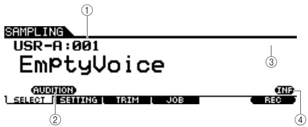
①UserVoice
Determines the User Voice to which the audio signals obtained via the Sampling operation are assigned.
| Settings | USR-A: 001 – USR-H: 127 |
(2) [SF1] AUDITION
You can hear the currently selected User Voice by holding this button. (If the User Voice is empty, no sound will result.)
(3) [F6] REC
Pressing this button calls up the Sampling Record Standby display.
(4) [SF6] INF
Pressing this button indicates the amount of Sampling memory used. Pressing this button again returns to the original display.
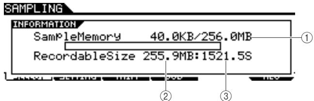
① Used/Total
Indicates the amount of memory being used and the total amount available.
② Recordable Size
Indicates the amount of free memory.
③ Recordable Time
Indicates the available Sampling time according to the available memory.
NOTE
Depending on the Sampling Frequency settings, the available sampling time differs as follows:
- Applied to both Mono and Stereo
4 Press the [F2] SETTING button to call up the Sampling Setting display, then make the necessary settings.
From this display, you can set the basic parameters such as recording source and sampling frequency.
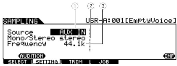
① Source (Sampling Source)
Determines the input connector via which the signal to be sampled will be received.
| Settings | AUX IN, resample |
| AUX IN | Analog audio from the AUX IN/SAMPLING IN jacks is recognized as the recording source. |
| resample | Audio signal from the output of the DTX900 is received internally and recognized as the recording source. |
② Mono/Stereo
Determines whether new samples will be recorded as stereo or mono samples.
| Settings | monoL, monoR, monoL+R, stereo |
| monoL | The L-channel signal will be recorded as a mono sample. |
| monoR | The R-channel signal will be recorded as a mono sample. |
| monoL+R | The L-channel and R-channel signals will be mixed and recorded as a mono sample. |
| stereo | A stereo sample will be recorded. |
③ Frequency
Determines the sampling frequency. The rate at which digital readings are taken is referred to as the sampling frequency. Higher sampling frequencies result in higher quality sound. Normally, this parameter should be set to "44.1kHz," the highest setting. If you wish to obtain a lo-fi sound, select a value other than 44.1kHz . At settings other than 44.1kHz , the sound monitored during recording may be different from the recorded sound, depending on the source signal.
| Settings | 44.1k (44.1 kHz), 22.0kLo (22.05 kHz Lo-Fi), 11.0kLo (11.025 kHz Lo-Fi), 5.5kLo (5.5125 kHz Lo-Fi) |
Press the [F1] SELECT button, then press the [F6] REC button.
When the User Voice indicated on the [F1] SELECT display contains no audio data, the Sampling Standby display appears.
When the User Voice indicated on the [F1] SELECT display contains the audio data, a confirmation message prompts you whether or not to overwrite the already recorded User Voice. If you do not want to overwrite the User Voice, press the [DEC/NO] button, select a different User Voice having no audio data, then press the [F6] REC button again.
![YAMAHA DTX-900 - Press the [F1] SELECT button, then press the [F6] REC button. - 1](/content/2025/01/114986/images/79e78f84140b84494330f9cb94c77c0e12299efca1f67203651486d705a29def.jpg)
① TriggerMode
Determines the method by which Sampling will be triggered. Normally, set this to "level."
| Settings | level, manual |
| level | Sampling starts as soon as an input signal exceeding the specified Trigger Level ② is received. |
| manual | Sampling starts soon after you press the [F6] START button. This setting lets you manually start Sampling, regardless of the input level from audio source. |
② Trigger Level
When the Trigger Mode ① is set to "level," you'll also need to set the Trigger Level. The level set here will be indicated as a triangle in the level meter. For best results, set this as low as possible to capture the entire signal, but not so low as to record unwanted noise.
| Range | 1 – 127 |
③ RecMonitor
Determines the output level of the monitor for the input signal. This monitor signal is output from the PHONES jack or the OUTPUT R and L/MONO jacks.
| Range | 0 – 127 |
④ RecGain
This parameter is available only when the Source is set to "resample" and determines the recording gain when resampling. The higher the value, the greater the volume of the resampled sound. Before executing the Sampling (Recording) operation, you can set the appropriate gain by checking the volume via the Level Meter while hitting the pad.
| Settings | -12dB, -6dB, +0dB, +6dB, +12dB |
(5) [F6] START
Press this button to start Sampling. When the Trigger mode ① is set to "level," pressing the [F6] START button calls up the WAITING indication on the display, and actual Sampling does not start until the proper level signal is received. When audio signal exceeding the specified Trigger Level ② is input to the instrument, the RECORDING indication replaces the WAITING indication and Sampling starts. When the Trigger Mode ① is set to "manual," pressing this button starts Sampling immediately.
6 Adjust the input sound level for optimum level.
Try to set the input level as high as possible without clipping for the best sound quality. Follow the instructions below to adjust the input level.
- When the Recording Source is set to "AUX IN," adjust the input signal level by using the GAIN knob on the rear panel. If you cannot adjust the input level appropriately, change the Mic/Line setting (page 128) in the Utility mode.
- When the Recording Source is set to "resample," adjust the input signal level by setting the RecGain parameter.
7 Press the [F6] START button to start the Sampling operation.
- When the Trigger Mode ① is set to "manual," pressing the button immediately starts Sampling (a RECORDING indication appears in the display).
![YAMAHA DTX-900 - Press the [F6] START button to start the Sampling operation. - 1](/content/2025/01/114986/images/c8b5d357a341ea38c1fcbef2911ed924ec2157c3e673f3be0491a6d15dc63fb7.jpg)
- When the Trigger Mode ① is set to "level," pressing the button enables Sampling but does not start it (a WAITING indication appears in the display).
![YAMAHA DTX-900 - Press the [F6] START button to start the Sampling operation. - 2](/content/2025/01/114986/images/37423bd14ce8c191f5ee83c000ccb6d7833c5e99dd5c4b5c42a25b87f2fb57e2.jpg)
8 Play the sound to be sampled.
When the Trigger Mode ① is set to "level" and an audio signal exceeding the specified Trigger Level ② is input to the instrument, the RECORDING indication replaces the WAITING indication and Sampling starts. During Sampling, a graphic representation of the recorded audio appears in the display.
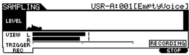
9 Press the [F6] STOP button to stop Sampling.
The Pad Assign display appears. From this display, you can hear the result of the Sampling operation by holding the [F3] AUDITION button and assign the recorded audio signal (or User Voice) to the Trigger Input Source (or pad).
![YAMAHA DTX-900 - Press the [F6] STOP button to stop Sampling. - 1](/content/2025/01/114986/images/15c2c9f2e2299e99014f710eb0d9c715557ae52512d12bac5aac9162f156a6ed.jpg)
① Pad Assign
Determines the Trigger Input Source to which the recorded audio signal (in other words, User Voice) is assigned. When "no assign" is selected, the recorded audio signal is not assigned to any Trigger Input Source but only to the User Voice selected on the [F1] SELECT display.
Settings
Refer to the Trigger Input Source on page 61.
(2) [F3] AUDITION
You can hear the recorded User Voice by holding this button. This lets you check whether the Sampling has been executed appropriately or not.
10 Press the [F3] AUDITION button to hear the sampled sound.
If you are not satisfied with the results and you wish to try again, press the [F4] CANCEL button to return to the Standby display and try Sampling from step 4.
11 Select the desired Trigger Input Source by setting the Pad Assign parameter.
The recorded audio signal (User Voice) will be assigned to the Trigger Input Source selected here instead of the previously assigned Voice.
NOTE
- If you exit from the Sampling operation display without assigning the User Voice to the pad, confirm that the [SOURCE] is shown in the top left of the display via [DRUM KIT] [F2] VOICE [SF1] SELECT, then assign the User Voice. If the [INPUT] is shown in the top left of the display, press the [SF5] button to alternate the display type to [SOURCE]. For details, see "When the INPUT display is called up:" on page 79.
12 If you are satisfied with the results, press the [F5] OK button to store the sampled sound as a “User voice.”
The [F1] SELECT display appears again.
13 If necessary, repeat steps 5 - 12 to assign another User Voice to a different pad.
14 Press the [DRUM KIT] button to enter the Drum Kit mode, and then press the [ENTER/STORE] button to store the Drum Kit settings.
For instructions, see page 42. This makes it possible to store the User Voice Assignment as a Drum Kit. If you wish to use a User Voice obtained via Sampling, select the Drum Kit number that you have stored here.
15 Save the created User Voice data to a USB storage device.
For detailed instructions on saving, see pages 55 and 114.
NOTICE
- The recorded audio data resides temporarily in DIMM (pages 76 and 147). Any data in DIMM will be lost when turning the power off. You should always save any data residing in DIMM to a USB storage device before turning off the power.
Trimming a User Voice
[F3]TRIM
From this display, you can use the Trim function to delete unwanted portions of the User Voice selected on the [F1] SELECT display, located ahead of the Start point and located after the End point.
Press the [SAMPLING] button to enter the Sampling mode.
The Sampling Select display appears.
2 Select the User Voice to be trimmed on the [F1] SELECT display.
3 Press the [F3] TRIM button to call up the Trimming display.
NOTE
- When a User Voice having no audio data is selected on the [F1] SELECT display, pressing the [F3] button cannot call up the Trimming display.
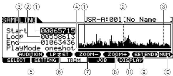
① Start (Start point)
Determines the Start point for playback of the audio data included in the User Voice. The portion of the audio to the left of this point will not be played back. When the cursor is located on the Start parameter, the Start Point is indicated as a vertical full line in the waveform display. When the cursor is not located on the Start parameter, the Start Point is indicated as a vertical dotted line in the waveform display.
② Loop (Loop Point)
Determines the Loop point at which loop playback starts. When the Play mode is set to "loop," the audio data included in the User Voice is played back between this Loop point and the End point. When the cursor is located on the Loop parameter, the Loop Point is indicated as a vertical full line in the waveform display. When the cursor is not located on the Loop parameter, the Loop Point is indicated as a vertical dotted line in the waveform display.
③ End (End Point)
Determines the End point for playback of the audio data included in the User Voice. The portion of the audio to the right of this point will not be played back. When the cursor is located on the End parameter, the End Point is indicated as a vertical full line in the waveform display. When the cursor is not located on the End parameter, the End Point is indicated as a vertical dotted line in the waveform display.
④ Play Mode
Determines how the selected User Voice is to be played back.
Settings oneshot, reverse, loop
oneshot The User Voice plays back one time from Start point to End point. This setting can be used for solos, sound effects and vocal passages that are used once without looping.
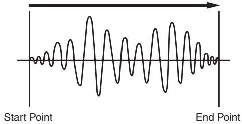
reverse The User Voice plays back one time in reverse from End point to Start point. This is useful for creating reversed cymbal sounds and other special effects.
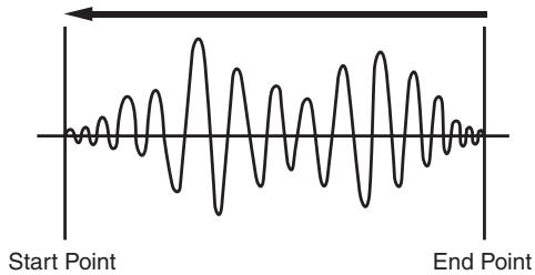
The User Voice plays back begins from the Start point, continues to the Loop point, then repeats indefinitely between the Loop point and End point. This setting is useful for short rhythmic passages, riffs and beats that you want to play back repeatedly and continuously.
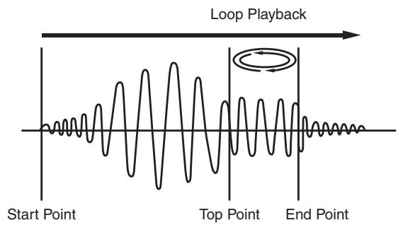
[SF1] AUDITION
You can hear the selected User Voice by holding this button.
⑥ [SF2] LP=ST
When the menu indication here is "LP=ST," the Start (Start Point) and the Loop (Loop Start Point) will share the same address, meaning that both of them will be changed simultaneously, even if just one of them is changed. Pressing the [SF2] button in this condition changes the menu from "LP=ST" to "LP≠ST." When the menu indication here is "LP≠ST," the Start (Start Point) and the Loop (Loop Start Point) can be changed independently. When pressing the [SF2] button in this condition, the address value of the Start will be copied to that of the Loop, with the result that both of them share the same address value. The menu indication also changes from "LP≠ST" to "LP=ST."
⑦ [SF3] ZOOM -
⑧ [SF4] ZOOM +
Press these buttons to zoom in and out of the waveform display of the User Voice in the display.
[SF5] SET END
Pressing this button calls up the display for determining the End Point, from which you can set the tempo, beat, and measure for the audio data included in the User Voice. For details, see page 141.
[SF6] NUM
You can use the [SF1] - [SF5] and [F1] - [F6] buttons as number buttons by pressing the [SF6] NUM button. For details, see page 14.
(1) [F5] DISPLAY
This menu item appears only when zooming in on the waveform display beyond a certain point (usually several presses of the ZOOM + button). When you zoom beyond this point, the display changes to a split screen, with the left side showing the Start Point area and the right side showing the End Point area. Pressing the [F5] DISPLAY in this condition alternates between the split screen display and a display showing either the Start Point area, Loop Point area, or the End Point area (depending on which parameter has been selected).
4 Specify the playback-only portion of the audio data in the User Voice by using the data dial, [INC/YES] and [DEC/NO] buttons.
In this step, you can set the Start Point, Loop Point and the End Point—all of which determine how much of the audio will play back and how it will play back. Use the ZOOM +/- controls (as well as the AUDITION control) to adjust how much of the waveform is displayed, making it easier to specify the playback-only portion.
5 If necessary, set the End Point as desired by using the display called up via the [SF5] SET END button.
From the display called up via the [SF5] SET END button, set the related parameters to determine the End Point. After setting the parameters, press the [SF1] AUDITION button to hear the result of your settings. If you are satisfied with the result, press the [F6] OK button to return to the original display.
For details, see page 141.
![YAMAHA DTX-900 - If necessary, set the End Point as desired by using the display called up via the [SF5] SET END button. - 1](/content/2025/01/114986/images/1af899fd029b89904e042f40bc9b2b7b65c84aec1cd2d1e57c3141a0fbdf686e.jpg)
6 From the [F3]TRIM display, press the [SF1] AUDITION button to hear the result of the settings.
If you are not satisfied with the result, repeat Steps 3-5 as desired.
7 Save the created User Voice data to a USB storage device.
For detailed instructions on saving, see pages 55 and 114.
NOTICE
- The User Voice data resides temporarily in DIMM (pages 76 and 147). Any data in DIMM will be lost when turning the power off. You should always save any data residing in DIMM to a USB storage device before turning off the power.
Setting the End Point by Specifying Tempo, Beat and Measure
[SF5] SET END
Explanations here apply to step 5 on page 140.
From the display called up via the [SF5] SET END button on the [F3] TRIM display, you can set the tempo, beat (time signature) and measure for the audio data included in the User Voice, resulting that the End Point is automatically determined. If you are satisfied with the result (press [SF1] to audition the result), press the [F6] OK button to return to the original display. If not, manually edit the End Point until you are satisfied.
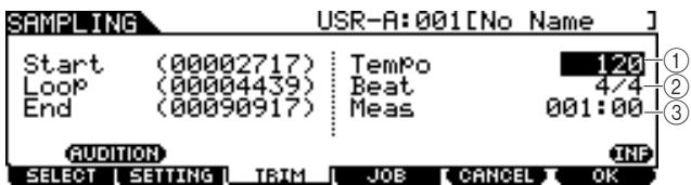
① Tempo
Determines the tempo of User Voice playback. Setting the value here changes the End Point so that the length between the Start Point and the End Point matches the settings of the Beat (time signature) and Measure.
Range 30-300
② Beat (Time signature)
Determines the time signature of User Voice playback. Setting the value here changes the End Point so that the length between the Start Point and the End Point matches the settings of the Tempo and Measure.
Settings 1/4 - 16/4, 1/8 - 16/8, 1/16 - 16/16
(3) Meas (Measure and beat)
Determines the length (measure and beat) of User Voice playback. Setting the value here changes the End Point so that the length between the Start Point and the End Point matches the settings of the Tempo and Beat (time signature).
| Range | Measure: 000 – 032 Beat: 00 – 15 (Varies depending on the Beat setting.) |
NOTE
- The Measure setting here indicates the length between the Start Point and End Point of the audio data included in the User Voice. When you wish to play two measures beginning from the Start Point of the User Voice, set the Measure parameter to "002:00."
Sampling Jobs
[F4] JOB
The Sampling Job lets you process and modify User Voices you have recorded. 14 Sampling Jobs are available.
01:Normalize
06: Stereo to Mono
02: Time-Stretch
07: Loop-Remix
03: Convert Pitch
08:Slice
04: Fade In/Out
09:Name
05: Convert Freq
10: Copy
11:Delete
12:Delete All
13: Extract
14: Optimize Memory
Basic Procedure of the Sampling Jobs
From the [F1] SELECT display, select the User Voice to which the Job is applied.
2 Press the [F4] JOB button.
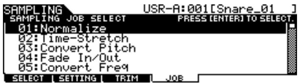
3 Move the cursor to the desired Job by using the data dial, [INC/DEC] and [DEC/NO] buttons or Cursor up/down buttons, then press the [ENTER/STORE] button.
The selected Job display appears.
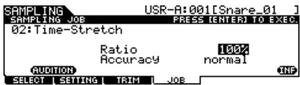
Press the [EXIT] button to go back to the Job menu display.
NOTE
- When the User Voice contains no audio data, pressing the [ENTER/STORE] button cannot call up the Job display, depending on the selected Job.
4 Move the cursor to the desired parameter, then set the value by using the data dial, [INC/YES] and [DEC/NO] buttons.
5 Press the [ENTER/STORE] button to execute the Job.
If "Are you sure?" appears, go to Step 6. If not, go to step 7.
NOTE
- When executing the "08: Slice" Job, you will need to set additional parameters: Select and Save To. Set these parameters, press the [ENTER/STORE] button, then press the [INC/YES] button to assign the sliced audio data to the specified User Voice. Repeat this procedure as desired (depending on the Subdivide setting) then go to Step 9.
6 Press the [INC/YES] button.
To cancel the Job, press the [DEC/NO] button then go back to step 4.
7 Press the [SF1] AUDITION button to hear the modified sound.
At this time, the User Voice has been modified temporarily and is not fixed as data.
Press the [F6] OK button if you are satisfied with the result of the Job operation.
If you are not satisfied with the result of the Job operation, press the [F5] CANCEL button and go back to Step 4.
NOTICE
- You cannot return the modified User Voice to the original after fixing the Job result. Important data should always be saved to a USB storage device connected to the USB TO DEVICE terminal (pages 55 and 114).
9 Save the created User Voice data to a USB storage device.
For detailed instructions on saving, see pages 55 and 114.
NOTICE
- The recorded audio data resides temporarily in DIMM (pages 76 and 147). Any data in DIMM will be lost when turning the power off. You should always save any data residing in DIMM to a USB storage device before turning off the power.
Sampling Jobs
The explanations here apply to Steps 4 - 8 of "Basic Procedure of the Sampling Jobs" on page 142.
01:Normalize
This Job maximizes (normalizes) the overall level of the specified User Voice. This is useful for bringing up the volume of a User voice that was inadvertently recorded at a low level.
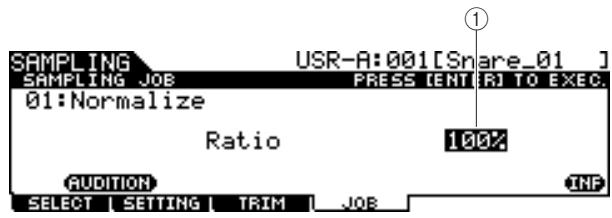
① Ratio
Determines the post-normalization level of the User Voice. A setting of 100% maximizes the level so that the highest peak level in the User Voice is just below clipping (maximum digital signal level). Settings higher than 100% will raise the User Voice level above the maximum, producing deliberate clipping. Normally, set this to 100% or less.
| Range | 1% – 800% |
02: Time Stretch
This Job lets you change the length of the User Voice without changing the pitch. By using this Job, you can synchronize playback of the audio data included in the User Voice with Song/Click playback, since changing the length of the User Voice also changes the playback tempo of the audio data included in the User Voice.
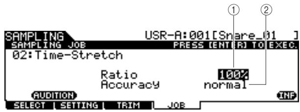
(1) Ratio
Determines the length of the post-process Voice as a ratio of the length of the original Voice (100%) . The tempo change and the appropriate Ratio value can be calculated as follows. Ratio value = (original tempo/modified tempo) x 100.
| Range | 1% – 400% |
② Accuracy
Determines the quality of the resulting Voice by specifying which aspect of the original is to be emphasized: sound quality or rhythmic feel.
| Settings | sound4 – sound1, normal, rhythm1 – rhythm2 |
| sound4 – sound1 | These settings place emphasis on sound quality, with the “sound4” setting producing the highest sound quality. |
| normal | Produces an optimum balance of sound quality and rhythmic feel. |
| rhythm1 – rhythm2 | These settings place emphasis on rhythmic feel, with the “rhythm2” setting producing the most accurate rhythmic feel. |
03: Convert Pitch
This Job lets you change the pitch of the User Voice without changing the tempo.
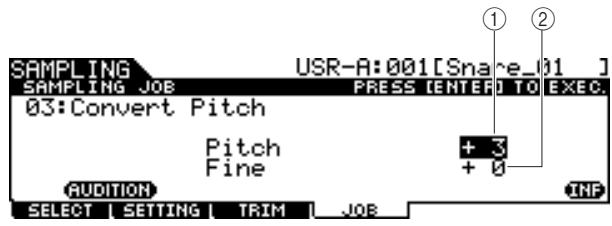
(1) Pitch
Determines the amount and direction of pitch shift in semitone increments.
| Range | -12 – +0 – +12 |
② Fine
Determines the amount and direction of pitch shift in cent increments. 1 cent is equivalent to 1/100 th of a semitone.
| Range | -50 – +0 – +50 |
04: Fade In/Out
This Job lets you create a fade-in for the starting portion of the User Voice and a fade-out for the ending section of the User Voice.
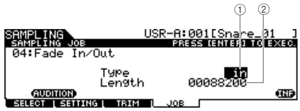
① Type (Fade Type)
Determines the type of level fade: fade-in or fade-out.
| Settings | in (fade-in), out (fade-out) |
(2) Length
Determines the length of the fade-in or fade-out. When a fade-in is selected, this parameter specifies the length of the fade starting at the specified Start point. When a fade-out is selected, this parameter specifies the length of the fade starting at the beginning of the fade and ending at the specified End point. A Length setting of 4410 is roughly equivalent to 0.1 seconds when the Frequency is set to 44.1kHz in the Setting display (page 136) of the Sampling mode.
| Range | 00000000 – End point |
05: Convert Freq
This Job lets you halve the sampling frequency of the specified User Voice. This can be used to convert hi-fi Voices to a lo-fi sound, as well as reduce the User Voice size by half.
06: Stereo to Mono
This Job lets you convert a stereo User Voice to a mono User Voice.
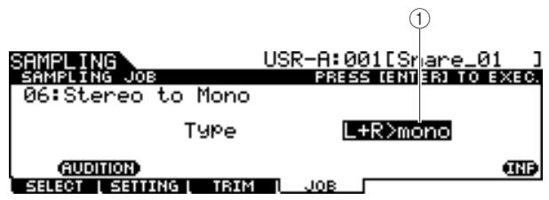
① Type
Determines which channel, or both channels, of the stereo User Voice will be converted to a mono User Voice.
| Settings | L+R>mono, L>mono, R>mono |
| L+R>mono | The left and right channels of a stereo Sample are mixed and converted to a mono Sample. |
| L>mono | The left channel of a stereo Sample is converted to a mono Sample. |
R>mono The right channel of the stereo sample is converted to a mono sample.
07: Loop-Remix
This Job lets you automatically cut the audio data included in the User Voice into separate "slices" and randomly rearrange the slices for special effects and unusual rhythmic variations.
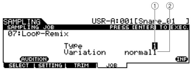
① Type
Determines the degree to which the looped portion of the User Voice will be sliced.
| Settings | 1 – 4 |
(2) Variation
Determines how the original User Voice is varied by this Job.
| Settings | normal1 - 2, reverse1 - 2 |
normal1 - 2 These settings slice and rearrange the User Voice data, without performing any other audio changes.
reverse1 - 2 In addition to slicing and rearranging, these settings reverse the playback of some of the slices.
08: Slice
This Job lets you divide the audio data included in the current User Voice into separate "slices" and assign them to the different User Voices.
This Job consists of two displays. The first display shown before executing the Slice operation lets you set how the audio data is divided while the second display shown after executing the Slice operation lets you assign the created "slice" to a different User Voice.
The first display (for setting the related parameters)
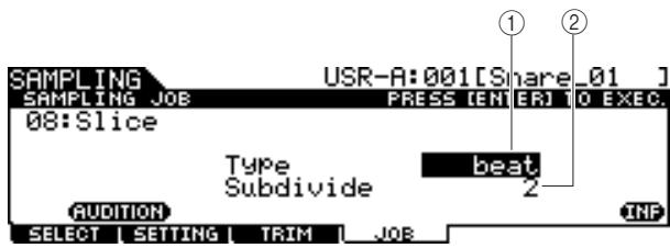
① Type
Determines the type that best suits the original phrase. Specifies how the User Voice is sliced, and to some extent determines the resulting sound quality.
| Settings | beat, phase1 – 4, quick |
| beat | This slice type is suited for percussive phrases such as drums or bass with a fast attack and short decay. |
| phrase1 – 4 | Ideal for phrases containing cymbals or other instruments with a long decay. |
| quick | Regardless of the phrase content, the audio data included in the User Voice is divided at numbers specified as the Sub Divide parameter. |
② SubDivide
Determines the number of slices.
| Range | 2 – 16 |
The second display (for setting the slice number and User Voice number as destination)
From this display (which appears after executing the Slice operation), you can assign each of the slices to a different User Voice. Set the Select parameter to the desired slice number, set the Save To parameter to the User Voice number as assignment destination, then press the [ENTER/STORE] button to execute the Assignment operation. The advantage of this feature is that you can assign each rhythmic slice to be triggered by a different pad (or note number), and thus the rhythm can be reconstructed in various ways by playing of the individual slices.
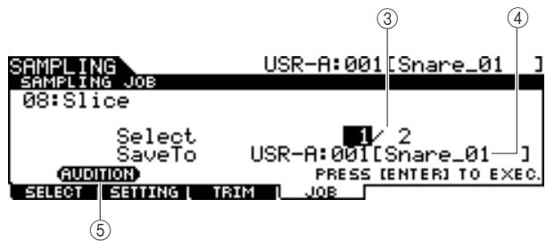
(3) Select
Determines the slice number.
SaveTo
Determines the User Voice number to which the specified slice is to be assigned.
| Settings | USR-A: 001 – USR-H: 127 |
⑤ [SF1] AUDITION
You can hear the created slice one by one by selecting the slice number ③ and holding the [SF1] AUDITION button. If you are satisfied with the result of each slice, assign each slice to a separate User Voice. If you are not satisfied with the result, press the [EXIT] button to go back to the first display, then execute the Slice operation again.
09: Name
Use this job to enter or change the name of the current User Voice.
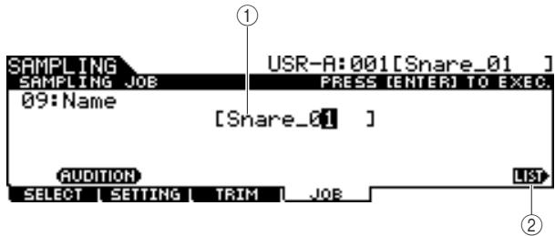
① Name
Determines the User Voice name (up to 10 characters). For detailed instructions on naming, refer to "Basic Operation" on page 15.
② [SF6] LIST
When the cursor is located on the Name box, you can call up the Character List by pressing the [SF6] LIST button and enter the name. For detailed instructions on naming, refer to "Basic Operation" on page 15.
10: Copy
This Job lets you copy the data of one User Voice to another.
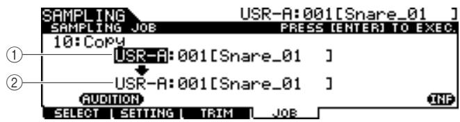
① User Voice bank and number as Source
② User Voice bank and number as Destination
Determines the User Voice banks and numbers as source and destination.
NOTICE
- This operation overwrites any data previously existing at the destination User Voice number.
11:Delete
This Job lets you delete a specific User Voice from memory.
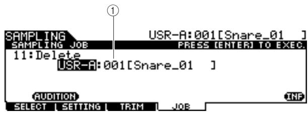
① User Voice bank and number
Determines the User Voice bank and number to be deleted.
12: Delete All
This Job lets you delete all User Voices. After calling up this display, press the [ENTER/STORE] button to delete all User Voices.
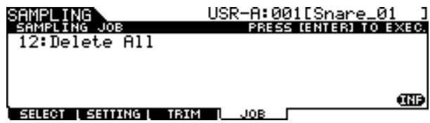
13: Extract
This Job lets you delete from memory all unnecessary audio data included in the User Voice (located ahead of the Start Point and located after the End Point), leaving only the portion of the sample you wish to keep.
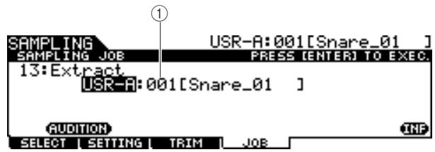
① User Voice bank and number
Determines the User Voice bank and number of which the unnecessary portion is to be extracted.
14: Optimize Memory
This Job optimizes the memory (DIMM) for Sampling.
Optimization consolidates areas of used and unused (available) memory to create the largest possible area of contiguous available memory. In some cases, the amount of remaining memory will be increased when you execute the Optimize Memory Job.
After calling up this display, press the [ENTER/STORE] button to execute the Optimize Memory Job.
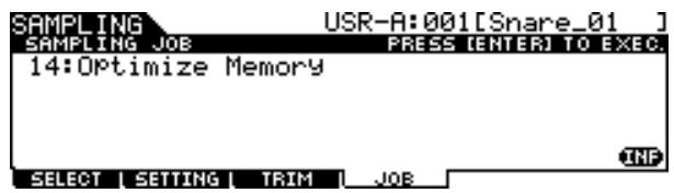
This section explains how to install DIMM memory modules to the DTX900.
Installation Precautions
WARNING
- Before beginning installation, switch off the power to the instrument and connected peripherals, and unplug them from the power outlet. Installation or removal of any devices should be started ONLY after the instrument (and the optional hardware) returns to normal room temperature. Then remove all cables connecting the instrument to other devices. (Leaving the power cord connected while working can result in electric shock. Leaving other cables connected can interfere with work.)
- Be careful not to drop any screws inside the instrument during installation. (This can be prevented by keeping the optional units and cover away from the instrument while attaching). If this does happen, be sure to remove the screw(s) from inside the unit before turning the power on. Loose screws inside the instrument can cause improper operation or serious damage. If you are unable to retrieve a dropped screw, consult your Yamaha dealer for advice.
- Install the optional units carefully as described in the procedure below. Improper installation can cause shorts which may result in irreparable damage and pose a fire hazard.
- Do not disassemble, modify, or apply excessive force to board areas and connectors on optional units. Bending or tampering with boards and connectors may lead to electric shock, fire, or equipment failures.
CAUTION
- It is recommended that you wear gloves to protect your hands from metallic projections on optional units and other components. Touching leads or connectors with bare hands may cause finger cuts, and may also result in poor electrical contact or electrostatic damage.
- Be careful of static electricity. Static electricity discharge can damage the IC chips on the DIMM. Before you handle the optional DIMM, to reduce the possibility of static electricity, touch unpainted metal parts or a ground wire on the devices that are grounded.
- Handle the optical units with care. Dropping or subjecting them to any kind of shock may cause damage or result in a malfunction.
- Do not touch the exposed metal parts in the circuit board. Touching these parts may result in a faulty contact.
- Be careful not to misplace any of the screws.
NOTICE
- Do not use any screws other than what are installed on the instrument. Use of incorrect screws can cause damage.
Compatible DIMMs
The DTX900 does not necessarily support all commercially available DIMMs. Yamaha cannot guarantee operation of DIMMs that you purchase.
Before purchasing DIMMs, please consult your Yamaha dealer, or an authorized Yamaha distributor (see list at end of the Owner's Manual) for advice, or visit the following website:
http://www.yamaha.co.jp/english/product/drums/ed/
DIMM Type and DIMM Configuration
-
Yamaha recommends that you purchase DIMMs that conform to the JEDEC* standard. Please be aware, however, that conformance to this standard does not constitute a guarantee that the DIMMs will operate correctly on the DTX900.
-
JEDEC (Joint Electron Device Engineering Council) sets standards for terminal configurations within electronic devices.
-
Use only 168-pin DIMMs of 64, 128 or 256MB capacity (synchronized DRAM; PC100 or PC133).
- When installing DIMMs, make sure to install them in a matched pair of the same capacity. You cannot install only one module and leave the second memory socket open. Also make sure each DIMM in the pair is of the same manufacturer and the same type. DIMMs of different makers and configurations may not work together.
- When purchasing DIMMs, make sure that the DIMM design does not utilize more than 18 memory chips per module. (DIMMs comprised of more than 18 chips do not operate correctly on the DTX900.)
$$ 6 4 \mathrm {M B} \times 2 = 1 2 8 \mathrm {M B} $$
$$ 1 2 8 M B \times 2 = 2 5 6 M B $$
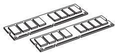
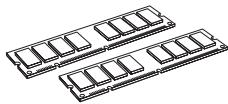
256MB x 2 = 512MB
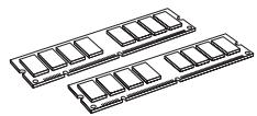
DIMM Installation
1 Turn the DTX900 power off, and disconnect the power cord.
2 Turn over the DTX900 so you can have direct access to the underside.
To protect the data dial and sliders from damage, place the DTX900 so the four corners are supported by something that provides sufficient support, such as magazines or cushions. Place supports at all four corners, taking care not to touch the Data dial and Sliders.

3 Remove the slot cover.
Remove the screws from the slot cover by using a Phillips screwdriver.
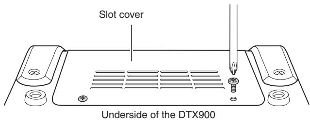
IMPORTANT
Keep the removed screws in a safe place. They will be used when re-attaching the cover to the instrument after installing the DIMMs.
4 Insert the two DIMMs into the DIMM sockets.
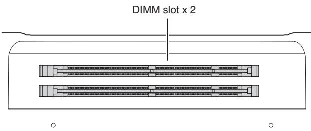
Location for DIMM installation
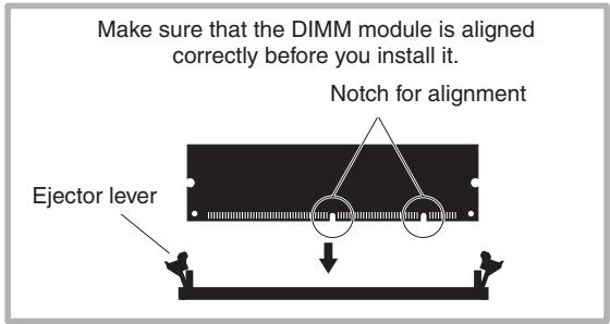
Installing the DIMM modules to the sockets
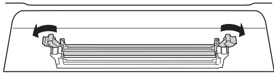
4-1 Press the ejector levers to the outside of the socket.
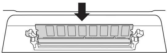
4-2 Insert the DIMM vertically in the socket. Press the DIMM in firmly until it "snaps" or locks in place.
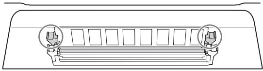
Confirm whether or not both the levers are firmly locked.
5 Re-install the cover you removed in step 3, in reverse order.
NOTE
- When you re-install the cover, make sure to steady the cover from the side with your hand.
6 Check that the installed DIMMs are functioning properly.
Set the DTX900 right-side up, and connect the AC power adaptor to the DC IN jack of the DTX900 and an AC wall outlet.
Turn on the power, go to the Sampling mode by pressing the [SAMPLING] button, then press the [SF6] INF button (page 136). If the DIMMs have been installed properly, the appropriate available memory size is indicated in the display.
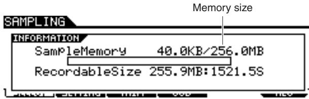
NOTE
- If the DIMMs have not been installed properly, the Sampling function will not work correctly. If this occurs, turn the power off, perform the instructions above again, and make sure to install the DIMMs firmly.
Removing DIMMs
Press the ejector lever until the DIMM unlocks.
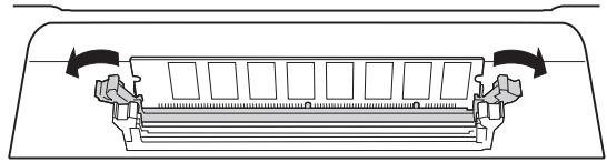
2 Pull the DIMM vertically out of the socket.
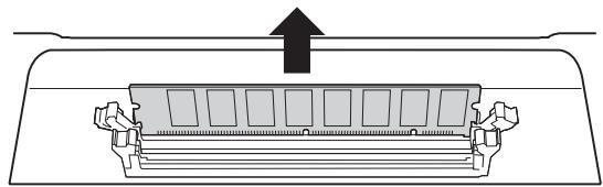
Troubleshooting
No sound, even when the pad is hit.
- Check whether or not the lamp of the TRIGGER INDICATOR lights when you hit the pad. If not, make sure the pads and Drum triggers (Yamaha DT20, etc.) are connected correctly to the input jacks of the DTX900. (page 12)
- Is the DTX900 properly connected to headphones or an external audio device such as an amplifier and speaker? (page 19)
- Is there a problem with the cable you are using?
- Check whether or not the power of the external audio device connected to the DTX900 is turned on. Also check whether or not the volume level of the external audio device is adjusted properly.
- Check whether or not the Pad Function is assigned to the pad you hit. The Pad Function parameter setting can be confirmed in the display called up via [UTILITY] [F2] PAD [SF2] PAD FUNC. If a specific function is assigned to the corresponding pad, hitting the pad triggers no sound.
- Check the Trigger Bypass parameter (page 126) in the display called up via [UTILITY] [F2] PAD [SF3] TRGBYPS. If this parameter is set to on, no sound is produced even if you hit any pad.
- Check the Local Control parameter (page 130) in the display called up via [UTILITY] [F5] MIDI [SF1] SWITCH. If this parameter is set to off, the internal tone generator will not accept the Trigger Input Signals.
No sound or the sound volume is lower than expected.
- Check whether or not the volume sliders (page 31) on the front panel of the DTX900 are set properly.
- Check the Volume parameter (page 80) in the display called up via [DRUM KIT] [F2] VOICE [SF2] OUT-TUNE. If this parameter value is too low, raise the value.
- Check the Volume parameter (page 95) in the display called up via [DRUM KIT] [F6] OTHER [SF1] COMMON. If this parameter value is too low, raise the value.
- Check the Volume parameter (page 124) in the display called up via [UTILITY] [F1] GENERAL [SF1] TG. If this parameter value is too low, raise the value.
- Check the Gain and Velocity Curve parameters (page 109) in the display called up via [TRIGGER] [F3] SENS. No sound may be produced depending on the settings on this display.
- Check the OutputSel parameter (page 81) in the display called up via [DRUM KIT] [F2] VOICE [SF2] OUT-TUNE. If this parameter is set to a value other than "L&R+ph," the sound of the corresponding pad is not output via the PHONES jack and OUTPUT jacks.
- Check the Attack and Decay parameters (page 83) in the display called up via [DRUM KIT] [F2] VOICE [SF3] EQ-TONE. No sound may be produced depending on the settings of these parameters.
- Check the Effect and Filter settings. No sound may be produced especially depending on the Filter settings.
The external MIDI tone generator produces no sound.
- Is the MIDI cable (connector) properly connected? (page 20)
- Make sure the MIDI Transmit Channels of the DTX900 match the MIDI Receive Channels of the connected external MIDI tone generators. For information about the MIDI settings in the Drum Kit mode, see page 96. For information about the MIDI settings during Song playback, see page 103.
- Check whether or not a specific drum instrument of the external tone generator is properly assigned to the corresponding MIDI note number (generated by hitting the pad connected to the DTX900). If no instrument is assigned, no sound is produced on the external tone generator even if you hit the pad.
- Make sure the Trigger Bypass parameter (page 126) is set to off in the display called up via [UTILITY] [F2] PAD [SF3] TRGBYPS.
- Check the MIDI IN/OUT parameter (page 131) in the display via [UTILITY] [F5] MIDI [SF3] OTHER. If this parameter is set to "USB," the DTX900 cannot communicate with the external MIDI tone generator connected via the MIDI cables.
Unexpected sound is produced.
- Check the Pad Type parameter in the display called up via [TRIGGER] [F2] TYPE. If the combination between the Input and the Pad Type is not appropriate, unexpected sound may be produced.
- When the external tone generator connected to the DTX900 via MIDI produces unexpected sound, check whether or not the Voice setting for the tone generator's MIDI channel equivalent to the Transmit channel of the DTX900 is properly set.
- Make sure you have not plugged the monaural phone plug or monaural pad when the power is still ON. This sets the rim switch ON on the DTX900. Turn the power OFF and ON again.
Sound is distorted.
- Are the Effect settings appropriate? Use of an Effect at certain settings may produce distortion.
- Check the Filter and Resonance parameters (page 83) in the display called up via the [DRUM KIT] [F2] VOICE [SF3] EQ-TONE. Distorted sound may be produced depending on the settings of these parameters. Excessively high filter resonance settings can cause distortion.
Is the MASTER VOLUME set so high that clipping is occurring?
Wrong pitch or unexpected pitch.
- Check the Tune parameter (page 124) in the display called up via [UTILITY] [F1] GENERAL [SF1] TG. If this parameter is set to a value other than "0," unexpected sound may be produced.
- Check the Tune parameter (page 80) in the display called up via [DRUM KIT] [F2] VOICE [SF2] OUT-TUNE. If this parameter is set to a value other than "0," unexpected sound may be produced.
No effects are applied.
- Check the Effect Bypass settings (page 89) in the displays called up via [DRUM KIT] [F4] EFFECT. If Bypass is turned on, the corresponding Effect is not applied to the sound.
- Check the Switch parameter (page 128) in the display called up via [UTILITY] [F3] EFFECT [SF2] MEF. If this parameter is set to "off," the Master Effect is not applied to the sound.
- Check the Reverb Send, Chorus Send and Variation Send parameters (page 80) in the display called up via [DRUM KIT] [F2] VOICE [SF2] OUT-TUNE. If these parameters are set to minimum values close to 0, it may sound as if no Effect is being applied to the sound.
- Check the Reverb Send and Chorus Send parameters (page 95) in the display called up via [DRUM KIT] [F6] OTHER [SF1] COMMON. If these parameters are set to minimum values close to 0, it may sound as if no Effect is being applied to the sound.
A Song cannot be started even when pressing the [▶/■] button.
- Does the selected Song actually contain data?
- Check the MIDI Sync parameter (page 131) in the display called up via [UTILITY] [F5] MIDI [SF2] SYNC. If this parameter is set to "MIDI," the Song of the DTX900 will play back only upon reception of external MIDI clock coming from the external MIDI sequencer or computer. In other words, the Song cannot play back even if you press the [▶/■] button.
Connected microphone does not work properly.
- Check the Mic/Line parameter (page 128) in the display called up via the [UTILITY] [F4] AUX IN [SF1] OUT-PUT. This parameter should be set to "mic" when using the microphone.
- Check whether the GAIN Knob (page 12) on the rear panel is set to minimum position or not.
Cannot record audio signals in the Sampling mode.
- If you cannot enter the Sampling mode even though you've pressed the [SAMPLING] button, check whether DIMMs have been installed or not. In order to enter the Sampling mode, DIMM modules must be installed. (page 147)
Is there enough Sample Memory available? (page 136)
Is the Sampling Source setting appropriate? (page 136)
Is the Trigger Mode set appropriately? (page 137)
Computer/MIDI instrument problems.
- Check the MIDI IN/OUT parameter (page 131) in the display called up via [UTILITY] [F5] MIDI [SF3] OTHER. If you are connecting a computer to the DTX900 via USB, this parameter should be set to "USB"; if you are connecting a MIDI device to the DTX900 via MIDI, this parameter should be set to "MIDI."
Cannot save data to the external USB storage device.
- Has the USB storage device you're using been properly formatted? (page 123)
- Is the USB storage device being used write protected? (Write-protect should be set to off for saving data.) (page 21)
- Is there enough empty memory space in USB memory? To check the amount of free capacity in USB memory, press the [SF6] button in the File mode.
The Trigger Signal from the acoustic drum is not stable.
- Check whether or not the Drum Trigger (Yamaha DT20, etc.) is attached to the acoustic drum with adhesive tape.
- Check all the items of "No sound or the sound volume is lower than expected" above.
- Is the cable securely connected to the Drum Trigger (Yamaha DT20, etc.) jack?
Double triggering problem.
- If the connected pads have an output or velocity control volume, adjust them. It may be a good idea to lower them.
- Check the Gain parameter (page 109) in the display called up via [TRIGGER] [F3] SENS. It may be a good idea to lower the value of this parameter.
- When using acoustic drums, are you using Drum Triggers (trigger sensors) made by manufacturers other than Yamaha? To ensure optimum operation, use only Yamaha Drum Triggers.
- When using acoustic drums, check whether or not the head of the drum is generating irregular vibration. If so, it may be necessary to mute the head.
- When using acoustic drums, make sure the Drum Trigger is attached near the rim (above the bearing) and not near the center of the head.
- When using acoustic drums, make sure that nothing is touching the Drum Trigger.
- Try increasing the value of the Reject Time parameter (page 110) to avoid double triggering. Note that the sound of a roll or flam cannot be properly produced if this parameter value is too high.
Crosstalk problem (unexpected sound is produced by other pads)
- When using acoustic drums, place the Drum Trigger away from any nearby drum.
- Try adjusting the Reject Level parameter (page 110) in the display called up via [TRIGGER] [F4] REJECT.
- If the pads have a level adjustment knob, adjust them.
- Try adjusting the minimum level parameter (page 110) in the display called up via [TRIGGER] [F3] SENS.
Sound is missing when performing a roll or flam on the pad.
- Check the Reject Level parameter (page 110) in the display called up via [TRIGGER] [F4] REJECT. It may be a good idea to lower the value of this parameter.
- Check the Mask Time parameter (page 94) in the display called up via [DRUM KIT] [F5] PAD [SF4] TRIG-GER. It may be a good idea to lower the value of this parameter.
Sound is cut off.
- Check the Mono/Poly parameter (page 84) in the display called up via [DRUM KIT] [F2] VOICE [SF4] OTHER. Set this parameter to "poly."
- Check the note settings in the Stack/Alternate display of the Drum Kit mode. If unnecessary notes are set, delete them.
Only one sound is produced even when two pads (drums) are hit.
- Try raising the value of the Gain parameter (page 109) for the pad (Trigger Input) that is not producing sound in the display called up via [TRIGGER] [F3] SENS.
- Try lowering the value of the Reject Level parameter (page 110) for the pad (Trigger Input) that is not producing sound.
- Check the Alternate Group parameter (page 84) for both of the pads in the display called up via [DRUM KIT] [F2] VOICE [SF4] OTHER. If both of the pads are assigned to the same Alternate Group, change the setting of either pad to a different value.
The sound volume is louder than expected.
- Check the Gain parameter (page 109) in the display called up via [TRIGGER] [F3] SENS. Try lowering the value of this parameter.
- Check the velocity curve settings (page 110) in the display called up via [TRIGGER] [F3] SENS. Set the appropriate velocity curve.
- Check the Trigger Velocity parameter (page 94) in the display called up via [DRUM KIT] [F5] PAD [SF4] TRIGGER. If this parameter is set to “127,” for example, the maximum volume sound is produced regardless of how soft your pad hitting may be. Change the value of this parameter to the appropriate one.
- Are you using a pad made by a manufacturer other than Yamaha? Depending on the manufacturer, output levels might be too large.
The sound does not stop.
- Press the [EXIT] button to stop the sound. The sound may continue when the Receive Key Off parameter is set to "off" in the display called up via [DRUM KIT] [F2] VOICE [SF4] OTHER.
The Pad Controller does not work as expected.
- Check the Pad Controller Type parameter (page 92) in the display called up via [DRUM KIT] [F5] PAD [SF1] PAD CTRL. If this parameter is set to "off," the Pad Controller installed to the connected pad does not work. Select the appropriate value.
- Check the Pad Type parameter (page 109) in the display called up via [TRIGGER] [F2] TYPE. If this parameter is not set to "TP120SD/100" (equipped with the Pad Controller), the Pad Controller does not work.
- Check whether or not the rim section is pressed. If so, the Pad Controller does not work.
The Closed Hi-Hat sound is not produced even if you press the Hi-Hat Controller by foot.
- Check the Pad Type parameter (page 109) in the display called up via [TRIGGER] [F2] TYPE. If the RHH135 or RHH130 is connected to the HI-HAT CONTROL jack as well as the HI-HAT jack, the Pad Type parameter with the INPUT set to "hihat" should be set to "RHH135" or "RHH130."
No sound results even if you hit the edge or cup section of the cymbal pad. The choke functions do not work.
- Check the Pad Type parameter (page 109) in the display called up via [TRIGGER] [F2] TYPE. If this parameter is set to an improper value (such as the model name of a snare or tom pad) and the INPUT parameter at left is set to ride (to which the ride cymbal pad is connected), select the appropriate value (model name of the ride cymbal).
Hi-hat splashes are not produced.
- Is the foot controller connected to the HI-HAT CONTROL jack?
- Check the Foot Splash Sensitivity parameter (page 126) in the display called up via [UTILITY] [F2] PAD [SF1] HI HAT. If this parameter is set to "off," the hi-hat splash sound will not be produced.
Sound is maintained even if the [ / ] button is pressed during Song playback.
- Check whether or not hitting the pad to which the Pad Song is assigned is recorded to the Song. If so and the Mode parameter is set to "play" or "cutoff" on the display called up via the [DRUM KIT] [F5] PAD [SF3] PAD-SONG, only the Pad Song playback cannot be stopped depending on the timing you press the [ / ] button during playback. If you cannot find the pad, you can stop the sound by changing the Drum Kit in the Drum Kit mode.
Display Messages
| LCD | Description |
| Are you sure? | Confirms whether you want to execute a specified operation or not. |
| Can't play SMF Format 1 data. | This message appears when you select and start the song with the SMF format 1 on the USB storage device. Convert the song to the SMF format 0, then play it again, since the DTX900 can handle only SMF format 0 song data. |
| Choose user song. | This message appears when you press the [F2] JOB button in the Song mode with a Preset Song selected. When you want to call up the Job display, select a User Song. |
| Click stored. | The settings in the Click mode have been stored. |
| Completed. | This appears when an operation such as Load, Save, Format and other Job has been completed. |
| Connecting USB device... | The DTX900 is currently recognizing the USB storage device connected to the USB TO DEVICE terminal. |
| Copy protected. | You have attempted to export or save a copy-protected digital audio source. |
| USB device full. | The USB storage device is full and no more data can be saved. Use a new USB storage device, or make space by erasing unwanted data from the storage device. |
| USB device not ready. | A USB storage device is not properly inserted in or connected to the DTX900. |
| USB device read/write error. | An error occurred while reading or writing to/from a USB storage device. |
| USB device write protected. | A USB storage device is write protected, or you have attempted to write to a read-only medium such as CD-ROM. |
| Executing... | A format operation or Job is being executed. |
| File already exists. | A file having the same name as the one you are about to save already exists. |
| File not found. | The specified file was not found on the external USB storage device during a Load operation. |
| Folder is not empty. | You have attempted to delete a folder that contains data. |
| Folder is too deep. | Directories below this level cannot be accessed. |
| Illegal file. | The file specified for loading is unusable by the DTX900 or cannot be loaded in the current mode. |
| Illegal file name. | The specified file name is invalid. Try entering a different name. |
| Illegal input. | An invalid input or value has been specified. Check the input method or value. |
| Illegal sample data. | The sample file specified for loading is unusable by the DTX900. |
| Illegal selection. | An unacceptable file has been specified in the Song job mode. |
| Illegal song number. | An unacceptable song number has been specified in the Song job mode. Select the song again. |
| Illegal track number. | An unacceptable track number has been specified in the Song job mode. Select the track again. |
| Incompatible USB device. | A USB device which cannot be used with the DTX900 has been connected to the USB TO DEVICE connector. |
| Invalid USB device. | The USB storage device is unusable. Format the USB storage device and try again. |
| MIDI buffer full. | Failed to process the MIDI data because too much data was received at one time. |
| MIDI data error. | An error occurred when receiving MIDI data. |
| No data. | When a Song Job was executed, the selected track or range contained no data. Select an appropriate track or range. |
| No DIMM memory installed. | An appropriate pair of expansion DIMMs has not been properly installed, or the pair is not properly matched. |
| No response from USB device. | There is no response from the USB device connected to the USB TO DEVICE terminal. |
| No sample data. | This message appears when a Sample-related Job cannot be executed because the specified Sample is not available. |
| Now loading... (xxxx) | Indicates that a file is being loaded. |
| Now saving... (xxxx) | Indicates that a file is being saved. |
| Now scanning autoloaded files. | The DTX900 is currently scanning for the files specified for Auto Load. |
| Now working... | The DTX900 is currently executing the memory arrangement after you have finished Sampling or have cancelled the Load/Save operation by pressing the [EXIT] button. |
| Overwrite? [YES]/[NO] | This message appears when the Save operation in the File mode will overwrite data on the USB storage device or the Sampling operation will overwrite the User Voice containing data. This message prompts you to confirm whether it is OK to continue the operation or not. |
| Please keep power on. | The data is being written to Flash ROM. Never attempt to turn off the power while data is being written to Flash ROM. Turning the power off while this message is shown results in loss of all user data and may cause the system to freeze (due to corruption of data in the Flash ROM). This may also result in the DTX900 being unable to properly start up the next time the power is turned on. |
| Please stop sequencer. | The operation you have attempted to execute cannot be done during Song playback. |
| Sample freq is too low. | The sampling frequency is too low and the Frequency Convert Job cannot be executed. |
| Sample is protected. | The sample cannot be overwritten because it is protected. |
| Sample is too long. | The Sample size is too large and the Time Stretch Job cannot be executed. |
| Sample is too short. | The Sample length is too short and the Frequency Convert Job cannot be executed. |
| Sample memory full. | The Sample memory is full and further Sampling operations, Jobs, or load operations cannot be executed. |
| Seq data is not empty. | This message appears if you attempt to record to a track that already contains data. Clear the track data in the Song Job mode or select a different track, then perform the Record operation. |
| Seq memory full. | The internal memory for Sequence data is full, preventing any further operation (such as recording, Job execution, or loading from the USB storage device). Try again after erasing unwanted user song. |
| System memory crashed. | Writing data to Flash ROM has failed. |
| Too manystk/alt. | Displayed when the memory for Stack/Alternate is full and cannot copy the drum kit or add new steps. Free up space by deleting unwanted Stack/Alternate data, then try again. |
| USB connection terminated. | A break in the connection with the USB storage device has occurred because of an abnormal electric current. Disconnect the USB storage device from the USB TO DEVICE connector, then press the [ENTER/STORE] button. |
| USB power consumption exceeded. | The power consumption of the USB storage device connected to the USB TO DEVICE connector exceeds the regulated value. |
| USB transmission error. | An error has occurred when communicating with the USB storage device. |
| Utility stored. | The settings in the Utility mode have been stored. |
Specifications
| Tone Generator | Tone Generator | AWM2 |
| Polyphony | 64 notes | |
| Wave | 205MB (when converted to 16-bit linear format) | |
| Voice | Preset: 1,115 drum voices, 211 melody voices (GM) | |
| Drum Kit | Preset: 50 kits User: 50 kits (in the Flash ROM) External: 1584 kits (or 99 x 16, in the external USB storage device) | |
| Effects | Reverb 9 types Chorus 19 types Variation 51 types (Drum Kit) Insertion 51 types (AUX IN/SAMPLING IN) Master Effect 9 types Master EQ 5 bands | |
| Trigger | Trigger Setup | Preset: 9 User: 5 |
| Pad songs | play, chase, cutoff 4 songs (max.) can be played simultaneously. | |
| Sequencer | Note Capacity | Approx. 152,000 notes |
| Note Resolution | 480 ppq (parts per quarter note) | |
| Song Recording type | Real time | |
| Song tracks | 2 tracks | |
| Songs | Demo: 3 songs Practice: 44 songs Pad song: 40 songs User: 50 songs | |
| Sequence Formay | DTX900 Original Format, SMF format 0 | |
| Click | Tempo | 30 – 300 , Tap tempo |
| Beat | 1/4 – 16/4, 1/8 – 16/8, 1/16 – 16/16 | |
| Timing | Accent, Quarter note, Eighth note, Sixteenth note, Triplet | |
| Click Voices | Preset: 8 User: 1 | |
| Training Functions | Measure break, Groove check, Rhythm gate | |
| Sampling | Samples | 1,016 (for the User Voices) |
| Sampling Sources | Audio input signals via AUX IN/SAMPLING IN, Audio output signals via OUTPUT (Resample) | |
| Sample Data Bits | 16bit | |
| Sampling Frequency | 44.1kHz, 22.05 kHz, 11.025 kHz, 5.5125 kHz (stereo/mono) | |
| Sampling Memory | Optionally installed, expandable to 512 MB (256 MB DIMM x 2 slots) * DIMMs are not installed to the instrument when shipped from the factory. | |
| Sample Length | Mono: 32MB Stereo: 64MB | |
| Sampling Time | 44.1kHz: 6 min. 20 sec. 22.05kHz: 12 min. 40 sec. 11.025kHz: 25 min. 20 sec. 5.5125kHz: 55 min. 40 sec. *Mono/Stereo | |
| Sample Format | DTX900 Original format, WAV, AIFF | |
| Others | Controllers | ■ Sliders MASTER, PHONES, CLICK, ACCOMP., KICK, SNARE, TOM, CYMBAL, HI-HAT, MISC. ■ Data dial |
| Displays | 240 x 64 dot graphic backlit LCD, 7-segment LED (3-digit) | |
| Connectors | ● MIDI IN/OUT ● USB TO DEVICE/TO HOST ● OUTPUT L/MONO, R (standard phone jack) ● DIGITAL OUT (EIAJ CP1201, IEC60958, S/P DIF) ● INDIVIDUAL OUTPUT 1 – 6 (standard phone jack) ● Trigger Input jacks 1 – 9, 12 – 15 (Standard stereo phone jack, L: Trigger Signal, R: Rim Switch) ● Trigger Input jacks 10 and 11 (Standard stereo phone jack, L: Trigger Signal, R: Trigger Signal) ● AUX IN/SAMPLING IN (Standard stereo phone jack) ● PHONES (Standard stereo phone jack) ● HI-HAT CONTROL (Standard stereo phone jack) ● DC IN 16V | |
| Power Consumption | 18W | |
| Dimensions, Weight | 334(W) x 285(D) x 96(H) mm, 3.6kg | |
| Accessories | AC Power Adaptor (Yamaha PA-300B, or an equivalent), Module stand, Module stand fastening screws (4; included) Owner's Manual (this document), Data List, DVD-ROM |
- Specifications and descriptions in this owner's manual are for information purposes only. Yamaha Corp. reserves the right to change or modify products or specifications at any time without prior notice. Since specifications, equipment or options may not be the same in every locale, please check with your Yamaha dealer.
Symbols
( note type icon) 100
(page) 87
(Standby/On) switch 12
A
AC Power Adaptor 6
ACCOMP slider 11,31
Accuracy 143
ADD 86
ALL 87
AltGroup (Alternate Group) 84
Attack 83
AUDITION 136, 138, 140, 145
Audition button 11
AutoLoad 125
AUX IN/SAMPLING IN jack 12
B
BANK 30
BANK MSB/LSB 96,103
BASS 39
BEAT 33, 38, 105, 133
Beat 45,102,141
Bell Shot 29
Bow Shot 28, 29
Break 107
BYPASS 89, 90, 91, 127, 129
C
Cable clip 12
Category 90, 91, 129
CC NUM 96
CC VALUE 96
CH 103
CH (MIDI channel) 86
Chain 7
[CHAIN] button 10
CHAIN NO. 133
Checkbox 23
CHOSEND(ChorusSend).....96,103
Choke 29
CHORD 86
Chorus 68, 71
Chorus Effect Category 89
Chorus Effect Type 89
Chorus Pan 89
Chorus Return 89
Chorus To Reverb 89
ChoSend (Chorus Send) 81, 95
CLEAR 86
Clear Song 99
Clear Track 101
CLICK 132
Click (Metronome) 32
[CLICK] button 10
CLICK slider 11,31
CLICK VOICE 105
ClockOut 131
Closed Rim Shot 28
COMPRESSOR & EQ 70
Convert Freq 144
Convert Pitch 143
Copy 146
Copy Destination 97
Copy Measure 101
Copy Song 99
Copy Source 97
Copy Track 101
Create Measure 102
Crosstalk 108
Current 114
Cursor buttons 11
Curve 110
CYMBAL slider 11, 31
D
Data dial 11
Data List 6
DC IN terminal 12
[DEC/NO] button 11
Decay 83
DELAY 71
DELETE 86
Delete 146
Delete All 146
Delete Measure 102
Demo Songs 35
Destination Drum Kit number 97
Destination measure number 101
Destination Track number 101
DeviceNo. 131
DIGITAL OUT connector 12
DIMM 76,147
DISPLAY 140
DISTORTION 70
Double triggering 108
DRAM 76
DRUM 39
DrumKit 30,36,40,62
Drum Kit Bank 125
[DRUM KIT] button 10
Drum Kit icon 30
Drum Kit No 125
Drum Kit number 30
Drum Trigger 7
Drum Voice 40,62
Dry Level 81
DTX900K 16
DTX950K 17
E
Edge Shot 28, 29
Edit Indicator 14
Effect Parameters 90, 91, 128, 129
Effect Types 70
Effects 68
End (End Point) 139
Ending measure number of
measure range 102
Ending measure number of
source measure range 101
[ENTER/STORE] button 11
Erase Measure 102
EXEC 114, 121, 123
[EXIT] button 11
EXT.KIT 103
External Drum Kit 77
Extract 146
F
[F1] - [F6] (Function) buttons 11
Factory Settings 23
Fade In/Out 144
Fast Forward 37
[FILE] button 10
File name input location 114, 115, 121
File Type 113
File/Directory (Folder)
selection box 114, 121
FILTER 103
Filter 83
Fine 143
FLANGER & PHASER 70
Flash ROM 76
FootClosePosi (Foot Close Position) 126
FootSplashSens (Foot Splash Sensitivity) 126
FREQ (Frequency) 127
Frequency 136
Function 95
Functions 13
G
GAIN 127
Gain 109
GAIN knob 12
GATETIME 87
Groove Check 50, 51
H
Head Shot 28
High Frequency 82
High Gain 82
HI-HAT CONTROL jack 12
Hi-Hat Controller 59, 95
Hi-Hat Cymbal 28
HI-HAT slider 11,31
Hi-Hat Splash 28
Hold Mode 94
1
Icon 97
[INC/YES] button 11
INDIVIDUAL OUTPUT 1-6jacks 12
IndivOutGain 124
INF 136
INFO (Information) 93
INPUT 40,41,79,80
INPUT (Trigger Input jack) 92,109,110
Input Lock 41, 79, 80, 86, 92, 94
InsConnect 129
INSERT 86
Insertion 68
Insertion A (Insertion A Category/Type) 129
Insertion B
(Insertion B Category/Type) 129
Internal Memory 76, 77
K
KICK slider 11, 31
KIT 132
KIT NO. 133
KITLOCK 36
L
L&RGain 124
LCD Contrast Control 12
LCD display 10
LED Display 10, 125
Length 144
LEVEL 110
LIST ...49, 97, 100, 111, 123, 134, 145
Local Control 130
LocalCtrl 130
LO-FI 70
Loop (Loop Point) 139
Loop-Remix 144
Low Frequency 82
Low Gain 82
LP=ST 140
M
manual 107, 137
Mask Time 94
Master Effect 68
Master EQ 68
MASTER slider 11,31
Meas (Insertion point) 102
Meas (Measure and beat) 141
MEAS (Measure) 37
Meas (Measure) 45
MeasLength (Measure Length) .....45
Measure 107
Measure Jobs 101
Measure/Break 107
Memory Structure 77
Merge 131
Mic/Line 128
Mid Frequency 82
Mid Gain 82
MIDQ 82
MIDI Ch 95
MIDI IN/OUT 131
MIDI IN/OUT connectors 12
MIDI note numbers 64
MIDI Out 107
MIDI SW (MIDI Switch) 96
MIDI Sync 131
MIDI Type 95
MISC 72
MISC slider 11, 31
Mix Track 100
Mode 93,107
Module stand 16, 17
Module stand fastening screws ... 16, 17
Mono/Poly 84
Mono/Stereo 128, 136
Mute 29
N
Name 49,97,100,145
NEW 114, 121
Normalize 143
Note 50
NOTE NO. 87
Note number 80
NUM 140
NUMBER (Chain number) 132
Number of measures to be inserted . 102
0
Open Rim Shot 28
Open/Close 28
Optimize Memory 146
OTHER 39
OUTPUT L/MONO and R jacks ....12
OutputSel 128
OutputSel (Output Select) 81, 107
Overdub 43
P
Pad 16
Pad Assign 138
Pad Controller 59, 92
Pad Controller Type 92
Pad Function 126
Pad Song 35,93
Pad Type 109
PadFunc 126
PAGE
80, 82, 84, 90, 91, 94, 128, 129
PAN 96,103
Pan 81, 128
Pan Depth 124
PHONES jack 12
PHONES slider 11,31
Pitch 143
play 107
Play Count 125
Play Mode 139
play&rec 107
Practice Songs 35
Pre 128, 129
PRE.KIT 103
Preset 90, 91
Q
Q (frequency bandwidth) 127
Q (Resonance) 83
Quantize 44, 100
Quantize (Resolution) 100
R
Ratio 143
RcvKeyOff (Receive Key Off) 84
Realtime Recording 43
REC 136
rec 107
RecCount 125
Receive10ch 130
ReceivePC 130
ReceivePC10ch 130
RecGain 137
RecMonitor 137
Recordable Size 136
Recordable Time 136
Reject Level From 110
Reject Level From ALL 110
Reject Time 110
Release 83
Repeat 37,93,100
RepeatPlayback 37
Replace 43
REVSEND(Reverb Send).....96,103
Reverb 68,71
Reverb Effect Type 89
Reverb Pan 89
Reverb Return 89
RevSend (Reverb Send) 81, 95
Rewind 37
Rhythm Gate 52
Rhythm Gate Range 52
Ride Cymbal 29
S
Sampling 65
[SAMPLING] button 10
Sampling Jobs 143
SaveTo 145
Select 145
SendHH 126
SeqCtrl 131
SET END 140
SET NAME 114, 121
[SF1] - [SF6] (Sub-Function)
buttons 11
SHAPE 127
Slice 145
SliderSel (Slider Select) 85
SMF 77
Snare 28
Snare Buzz 93
SNARE slider 11, 31
Snares Adjust 93
Snares On/Off 92
SONG 132
Song Bank 125
Song bank and number 46
[SONG] button 10
Song Jobs 99
Song name 35
Song Name, Tempo, Repeat 100
Song No 125
Song No (Song number) 93
SONG NO. 133
Song number 35, 99
SOURCE 40, 41, 79
Source 136
SOURCE (Trigger
Input Source) 86,93,94,126
Source Drum Kit number 97
Source Song number 101
Source Track number 101
STACK/ALTERNATE COPY 97
Standard MIDI file 77
Standby/On switch 12
START 137
Start (Start point) 139
Starting measure number of measure range 102
Starting measure number of source measure range 101
STEP 86,87,132,133
Stereo to Mono 144
SUBDIVIDE 105
SubDivide 145
Sub-Functions 13
Swing 50
Switch 128
T
Tap Tempo 34
TECH 72
TEMPO 33, 34, 38, 105, 133
Tempo 45,95,100,141
Tempo Link 125
TG SW (Tone Generator Switch) ....96
ThruPort 131
Time Signature ....33, 38, 45, 105, 141
Time Stretch 143
Tom 28
TOM slider 11,31
Tone Generator 7,57
TR1 (Track 1) 39
TR2 (Track 2) 39
Track 48,100,101,102
Track (Recording Track) 44
Track Jobs 100
TRANSMIT 96,103
Transport buttons 11
TREMOLO & ROTARY 71
TrggrMode (Trigger Mode) 137
TrigAltGroup (Trigger Alternate Group) 94
TrigBypass 126
[TRIGGER] button 10
TRIGGER INDICATOR 11
Trigger Input 51, 52
Trigger Input jack 12,60
Trigger Input jack as copy destination 111
Trigger Input jack as copy source ... 111
Trigger Input Level Indicator 22
Trigger Input Source 58, 61
Trigger Level 137
Trigger No 125
Trigger Setup 22,60
Trigger Setup List 23
Trigger Setup number 22
Trigger Setup number as copy destination 111
Trigger Setup number as copy source 111
Trigger Signals 58
TriggerNo 22
TrigLink (Trigger Link) 94
TrigMono/Poly (Trigger Mono/Poly) 94
TrigVelocity(Trigger Velocity) 94
Tune 124
TUNING 106
Tuning 80
TYPE 114, 115, 116, 121, 133
Type.....90,91,97,128,129,144,145
Type (Fade Type) 144
Type (Recording Type) 44
U
USB terminals 12
Used/Total 136
User Drum Kit 77
User Memory 76
User Song 77
User Trigger Setups 77
User Voice 136
User Voice bank and number ..115, 146
User Voice bank and number as Destination 146
User Voice bank and number as Source 146
USR.KIT 103
[UTILITY] button 10
V
Variation 68, 144
Variation Effect Category 89
Variation Effect Type 89
Variation Pan 89
Variation Return 89
Variation To Chorus 89
Variation To Reverb 89
VarSend (Variation Send) 81
VCE NUM (Voice Number) 96
VEL (Velocity) 110
VELOCITYLIMIT 87
VelSensDpt
(Velocity Sensitivity Depth) 85
VelSensOfs
(Velocity Sensitivity Offset) 85
Voice category 79, 106
Voice Job 103
VOICE NUM (Voice Number) .... 103
Voice number 80, 106
Voice Set 40, 62
Voice Set category 40, 79
Voice Set number 41, 79
VOLUME 96,103
Volume 80,95,124,128
VOLUME (ACC) 105
VOLUME (eighth note triplet) 105
VOLUME (eighth notes) 105
VOLUME (quarter note) 105
VOLUME (sixteenth notes) 105
Volume Label 123
W
WAH 70
Z
ZOOM-,+ 140
About the Accessory Disk
SPECIAL NOTICE
The software included in the accessory disk and the copyrights thereof are under exclusive ownership by Steinberg Media Technologies GmbH.
- Use of the software and this manual is governed by the license agreement which the purchaser fully agrees to upon breaking the seal of the software packaging. (Please read carefully the Software Licensing Agreement at the end of this manual before installing the application.)
- Copying of the software or reproduction of this manual in whole or in part by any means is expressly forbidden without the written consent of the manufacturer.
- Yamaha makes no representations or warranties with regard to the use of the software and documentation and cannot be held responsible for the results of the use of this manual and the software.
- This disk is NOT for audio/visual purpose. Do not attempt to play the disk on an audio/visual CD/DVD player. Doing so may result in irreparable damage to your player.
- Note that Yamaha does not offer technical support for the DAW software in the accessory disk.
About the DAW software in the accessory disk
The accessory disk contains DAW software both for Windows and Macintosh.
NOTE
- Make sure to install DAW software under the "Administrator" account.
- In order to have continuous use of the DAW software in the accessory disk, including support and other benefits, you will need to register the software and activate your software license by starting the software while the computer is connected to the Internet. Click the "Register Now" button shown when the software is started, then fill in all required fields for registration. If you do not register the software, you will be unable to use it after a limited period of time expires.
- If you are using a Macintosh computer, double-click the "****.mpkg" file to start installation.
For information about the minimum system requirements and latest information on the software in the disk, check the web site below.
About software support
Support for the DAW software in the accessory disk is provided by Steinberg on its website at the following address.
http://www.steinberg.net
You can visit the Steinberg site also via the Help menu of the included DAW software. (The Help menu also includes the PDF manual and other information on the software.)
ATTENTION
SOFTWARE LICENSE AGREEMENT
PLEASE READ THIS SOFTWARE LICENSE AGREEMENT ("AGREEMENT") CAREFULLY BEFORE USING THIS SOFTWARE. YOU ARE ONLY PERMITTED TO USE THIS SOFTWARE PURSUANT TO THE TERMS AND CONDITIONS OF THIS AGREEMENT. THIS AGREEMENT IS BETWEEN YOU (AS AN INDIVIDUAL OR LEGAL ENTITY) AND YAMAHA CORPORATION ("YAMAHA").
BY BREAKING THE SEAL OF THIS PACKAGE YOU ARE AGREEING TO BE BOUND BY THE TERMS OF THIS LICENSE. IF YOU DO NOT AGREE WITH THE TERMS, DO NOT INSTALL, COPY, OR OTHERWISE USE THIS SOFTWARE.
THIS AGREEMENT PROVIDES YOUR USE-CONDITIONS ABOUT THE "DAW" SOFTWARE OF STEINBERG MEDIA TECHNOLOGIES GMBH("STEINBERG") WHICH IS BUNDLED WITH THIS PRODUCT. SINCE THE END-USER SOFTWARE LICENSE AGREEMENT (EUSLA) SHOWN ON YOUR PC-DISPLAY IN YOUR INSTALLING THE "DAW" SOFTWARE IS REPLACED BY THIS AGREEMENT, YOU SHOULD DISREGARD THE EUSLA. THAT IS, IN THE INSTALLING PROCESS, YOU SHOULD SELECT "AGREE" WITH THE EUSLA, WITHOUT YOUR JUDGMENT THERETO, SO AS TO PROCEED TO THE NEXT PAGE.
1. GRANT OF LICENSE AND COPYRIGHT
Yamaha hereby grants you the right to use one copy of the software program(s) and data ("SOFTWARE") accompanying this Agreement. The term SOFTWARE shall encompass any updates to the accompanying software and data. The SOFTWARE is owned by STEINBERG, and is protected by relevant copyright laws and all applicable treaty provisions. Yamaha has acquired the sublicense right to license you to use the SOFTWARE. While you are entitled to claim ownership of the data created with the use of SOFTWARE, the SOFTWARE will continue to be protected under relevant copyrights.
- You may use the SOFTWARE on a single computer.
- You may make one copy of the SOFTWARE in machine-readable form for backup purposes only, if the SOFTWARE is on media where such backup copy is permitted. On the backup copy, you must reproduce Yamaha's copyright notice and any other proprietary legends that were on the original copy of the SOFTWARE.
- You may permanently transfer to a third party all your rights in the SOFTWARE only when you transfer this product together, provided that you do not retain any copies and the recipient reads and agrees to the terms of this Agreement.
2. RESTRICTIONS
You may not engage in reverse engineering, disassembly, decompilation or otherwise deriving a source code form of the SOFTWARE by any method whatsoever. You may not reproduce, modify, change, rent, lease, or distribute the SOFTWARE in whole or in part, or create derivative works of the SOFTWARE.
You may not electronically transmit the SOFTWARE from one computer to another or share the SOFTWARE in a network with other computers.
You may not use the SOFTWARE to distribute illegal data or data that violates public policy.
You may not initiate services based on the use of the SOFTWARE without permission by Yamaha Corporation.
Copyrighted data, including but not limited to MIDI data for songs, obtained by means of the SOFTWARE, are subject to the following restrictions which you must observe.
Data received by means of the SOFTWARE may not be used for any commercial purposes without permission of the copyright owner.
Data received by means of the SOFTWARE may not be duplicated, transferred, or distributed, or played back or performed for listeners in public without permission of the copyright owner.
The encryption of data received by means of the SOFTWARE may not be removed nor may the electronic watermark be modified without permission of the copyright owner.
3. TERMINATION
This Agreement becomes effective on the day that you receive the SOFTWARE and remains effective until terminated. If any copyright law or provisions of this Agreement is violated, the Agreement shall terminate automatically and immediately without notice from Yamaha. Upon such termination, you must immediately destroy the licensed SOFTWARE, any accompanying written documents and all copies thereof.
4. LIMITED WARRANTY ON MEDIA
As to SOFTWARE sold on tangible media, Yamaha warrants that the tangible media on which the SOFTWARE is recorded will be free from defects in materials and workmanship under normal use for a period of fourteen (14) days from the date of receipt, as evidenced by a copy of the receipt. Yamaha's entire liability and your exclusive remedy will be replacement of the defective media if it is returned to Yamaha or an authorized Yamaha dealer within fourteen days with a copy of the receipt. Yamaha is not responsible for replacing media damaged by accident, abuse or misapplication. TO THE FULLEST EXTENT PERMITTED BY LAW, YAMAHA EXPRESSLY DISCLAIMS ANY IMPLIED WARRANTYES ON THE TANGIBLE MEDIA, INCLUDING THE IMPLIED WARRANTYES OF MERCHANTABILITY AND FITNESS FOR A PARTICULAR PURPOSE.
5. DISCLAIMER OF WARRANTY ON SOFTWARE
You expressly acknowledge and agree that use of the SOFTWARE is at your sole risk. The SOFTWARE and related documentation are provided "AS IS" and without warranty of any kind. NOTWITHSTANDING ANY OTHER PROVISION OF THIS AGREEMENT, YAMAHA EXPRESSLY DISCLAIMS ALL WARRANTYES AS TO THE SOFTWARE, EXPRESS, AND IMPLIED, INCLUDING BUT NOT LIMITED TO THE IMPLIED WARRANTY OF MERCHANTABILITY, FITNESS FOR A PARTICULAR PURPOSE AND NON-INFRINGEMENT OF THIRD PARTY RIGHTS. SPECIFICALLY, BUT WITHOUT LIMITING THE FOREGOING, YAMAHA DOES NOT WARRANTY THAT THE SOFTWARE WILL MEET YOUR REQUIREMENTS, THAT THE OPERATION OF THE SOFTWARE WILL BE UNINTERRUPTED OR ERROR-FREE, OR THAT DEFECTS IN THE SOFTWARE WILL BE CORRECTED.
6. LIMITATION OF LIABILITY
YAMAHA'S ENTIRE OBLIGATION HEREUNDER SHALL BE TO PERMIT USE OF THE SOFTWARE UNDER THE TERMS HEREOF. IN NO EVENT SHALL YAMAHA BE LIABLE TO YOU OR ANY OTHER PERSON FOR ANY DAMAGES, INCLUDING, WITHOUT LIMITATION, ANY DIRECT, INDIRECT, INCIDENTAL OR CONSEQUENTIAL DAMAGES, EXPENSES, LOST PROFITS, LOST DATA OR OTHER DAMAGES ASRISING OUT OF THE USE, MISUSE OR INABILITY TO USE THE SOFTWARE, EVEN IF YAMAHA OR AN AUTHORIZED DEALER HAS BEEN ADVISED OF THE POSSIBILITY OF SUCH DAMAGES. In no event shall Yamaha's total liability to you for all damages, losses and causes of action (whether in contract, tort or otherwise) exceed the amount paid for the SOFTWARE.
7. GENERAL
This Agreement shall be interpreted according to and governed by Japanese law without reference to principles of conflict of laws. Any dispute or procedure shall be heard before the Tokyo District Court in Japan. If for any reason a court of competent jurisdiction finds any portion of this Agreement to be unenforceable, the remainder of this Agreement shall continue in full force and effect.
8. COMPLETE AGREEMENT
This Agreement constitutes the entire agreement between the parties with respect to use of the SOFTWARE and any accompanying written materials and supersedes all prior or contemporaneous understandings or agreements, written or oral, regarding the subject matter of this Agreement. No amendment or revision of this Agreement will be binding unless in writing and signed by a fully authorized representative of Yamaha.
For details of products, please contact your nearest Yamaha representative or the authorized distributor listed below.
Yamaha Canada Music Ltd.
135 Milner Avenue, Scarborough, Ontario,
M1S 3R1, Canada
Tel: 416-298-1311
U.S.A.
Yamaha Corporation of America
6600 Orangethorpe Ave., Buena Park, Calif. 90620,
U.S.A.
Tel: 714-522-9011
CENTRAL & SOUTH AMERICA
MEXICO
Yamaha de Mexico S.A. de C.V.
Calz. Javier Rojo Gomez #1149
Col. Guadalupe del Moral
C.P.09300, Mexico,D.F.,Mexico
Tel: 55-5804-0600
BRAZIL
PANAMA AND OTHER LATIN
AMERICAN COUNTRIES/
CARIBBEAN COUNTRIES
Yamaha Music Latin America, S.A.
Torre Banco General, Piso 7, Urbanizacion Marbella,
Sherbourne Drive, Tilbrook, Milton Keynes,
MK7 8BL, England
Tel: 01908-366700
GERMANY
Yamaha Music Europe GmbH
Siemensstraße 22-34, 25462 Rellingen, Germany
Tel: 04101-3030
Branch Switzerland in Zurich
Seefeldstrasse 94, 8008 Zurich, Switzerland
Tel: 01-383 3990
AUSTRIA
Yamaha Music Europe GmbH Branch Austria
Schleiergasse 20, A-1100 Wien, Austria
Tel: 01-60203900
CZECH REPUBLIC/SLOVAKIA/
HUNGARY/SLOVENIA
Yamaha Music Europe GmbH Branch Austria
Schleiergasse 20, A-1100 Wien, Austria
Tel: 01-602039025
POLAND/LITHUANIA/LATVIA/ESTONIA
Yamaha Music Europe GmbH
147 Skiathou Street, 112-55 Athens, Greece
Tel: 01-228 2160
SWEDEN
Yamaha Scandinavia AB
J.A.Wettergrens Gata 1,Box 30053
S-400 43 Göteborg, Sweden
Tel: 031 89 34 00
DENMARK
YS Copenhagen Liaison Office
Generatorvej 6A, DK-2730 Herlev, Denmark
Tel: 44 92 49 00
FINLAND
F-Musiik
Kluuvikatu 6, P.O. Box 260,
SF-00101 Helsinki, Finland
Tel: 09 618511
NORWAY
Yamaha Music (Russia)
Office 4015, entrance 2, 21/5 Kuznetskii
Most street, Moscow, 107996, Russia
Tel: 495 626 0660
OTHER EUROPEAN COUNTRIES
Yamaha Music Europe GmbH
Siemensstraße 22-34, 25462 Rellingen, Germany
Tel: +49-4101-3030
AFRICA
Yamaha Corporation,
Asia-Pacific Music Marketing Group
Nakazawa-cho 10-1, Naka-ku, Hamamatsu,
Japan 430-8650
Tel: +81-53-460-2312
MIDDLE EAST
TURKEY/CYPRUS
Yamaha Music Europe GmbH
Siemensstraße 22-34, 25462 Rellingen, Germany
Tel: 04101-3030
OTHER COUNTRIES
Yamaha Music Gulf FZE
LOB 16-513, P.O.Box 17328, Jubel Ali,
Dubai, United Arab Emirates
Tel: +971-4-881-5868
ASIA
THE PEOPLE'S REPUBLIC OF CHINA
Yamaha Music & Electronics (China) Co., Ltd.
2F, Yunhedasha, 1818 Xinzha-lu, Jingan-qu,
Shanghai, China
Tel: 021-6247-2211
HONG KONG
Tom Lee Music Co., Ltd.
11/F., Silvercord Tower 1, 30 Canton Road,
Tsimshatsui, Kowloon, Hong Kong
Tel: 2737-7688
INDIA
Yamaha Music India Pvt. Ltd.
5F Ambience Corporate Tower Ambience Mall Complex
Ambience Island, NH-8, Gurgaon-122001, Haryana, India
Tel: 0124-466-5551
INDONESIA
PT. Yamaha Music Indonesia (Distributor)
PT. Nusantik
Gedung Yamaha Music Center, Jalan Jend. Gatot
SubROTO Kav. 4, Jakarta 12930, Indonesia
Tel: 21-520-2577
KOREA
Yamaha Music Korea Ltd.
8F, 9F, Dongsung Bldg. 158-9 Samsung-Dong,
Kangnam-Gu, Seoul, Korea
Tel: 080-004-0022
MALAYSIA
Yamaha Music Malaysia, Sdn., Bhd.
Lot 8, Jalan Perbandaran, 47301 Kelana Jaya,
Petaling Jaya, Selangor, Malaysia
Tel: 3-78030900
PHILIPPINES
Yupangco Music Corporation
339 Gil J. Puyat Avenue, P.O. Box 885 MCPO,
Makati, Metro Manila, Philippines
Tel: 819-7551
SINGAPORE
Yamaha Music Asia Pte., Ltd.
03-11 A-Z Building
140 Paya Lebor Road, Singapore 409015
Tel: 747-4374
TAIWAN
Yamaha KHS Music Co., Ltd.
3F, #6, Sec.2, Nan Jing E. Rd. Taipei.
Taiwan 104, R.O.C.
Tel: 02-2511-8688
THAILAND
Siam Music Yamaha Co., Ltd.
4, 6, 15 and 16th floor, Siam Motors Building,
891/1 Rama 1 Road, Wangmai,
Pathumwan, Bangkok 10330, Thailand
Tel: 02-215-2626
OTHER ASIAN COUNTRIES
Yamaha Corporation,
Asia-Pacific Music Marketing Group
Nakazawa-cho 10-1, Naka-ku, Hamamatsu,
Japan 430-8650
Tel: +81-53-460-2317
OCEANIA
AUSTRALIA
Yamaha Music Australia Pty. Ltd.
Level 1, 99 Queensbridge Street, Southbank,
Victoria 3006, Australia
Tel: 3-9693-5111
NEW ZEALAND
Music Works LTD
P.O.BOX 6246 Wellesley,Auckland 4680,
New Zealand
Tel: 9-634-0099
COUNTRIES AND TRUST
TERRITORIES IN PACIFIC OCEAN
Yamaha Corporation,
Asia-Pacific Music Marketing Group
Nakazawa-cho 10-1, Naka-ku, Hamamatsu,
Japan 430-8650
Tel: +81-53-460-2312
SY51
HEAD OFFICE
Yamaha Corporation, Pro Audio & Digital Musical Instrument Division
Nakazawa-cho 10-1, Naka-ku, Hamamatsu, Japan 430-8650 Tel: +81-53-460-2432

YAMAHA
- SPECIFICATIONS SUBJECT TO CHANGE:
- NOTICE:
- ENVIRONMENTAL ISSUES:
- Battery Notice:
- Warning:
- Disposal Notice:
- NAME PLATE LOCATION:
- Model
- Serial No.
- Purchase Date
- PLEASE KEEP THIS MANUAL
- FCC INFORMATION (U.S.A.)
- COMPLIANCE INFORMATION STATEMENT (DECLARATION OF CONFORMITY PROCEDURE)
- IMPORTANT NOTICE FOR THE UNITED KINGDOM Connecting the Plug and Cord
- Information for Users on Collection and Disposal of Old Equipment
- OBSERVERA!
- WARNING
- Power supply/AC power adaptor
- Do not open
- Water warning
- Fire warning
- If you notice any abnormality
- CAUTION
- Location
- Connections
- Handling caution
- NOTICE
- ■ Handling and Maintenance
- Saving data
- ■ About the latest Firmware Version
- About the pads
- Introduction
- Included Accessories
- Information
- About copyrights
- ■ About functions/data bundled with the instrument
- About this manual
- Main Features
- Drum Trigger
- ■ Tone Generator
- ■ Music Sequencer (Song)
- High-performance Metronome (Click)
- Chain
- Interfaces
- Contents
- Panel Controls. 10
- Basic Operation 13
- Setting Up 16
- Quick Guide 28
- How to Play the Drum Pads 28
- Playing the DTX900 30
- Playing Along With the Click 32
- Tap Tempo 34
- Playing Along With a Song 35
- Creating a Drum Kit 40
- Recording Your Drum Performance to a Song... 43
- Using the Groove Check Function 50
- Saving the Created Data to a USB Storage
- Device 54
- Reference 57
- Basic Structure of the DTX900 57
- Drum Kit Mode [DRUM KIT] 78
- Song Mode [SONG] 98
- Click Mode [CLICK] 104
- Trigger Mode [TRIGGER] 108
- File Mode [FILE] 112
- Utility Mode [UTILITY] 124
- Chain Mode [CHAIN] 132
- Sampling Mode [SAMPLING] 135
- Appendix 147
- ■ Front Panel
- LCD display
- NOTE
- LED display
- [DRUM KIT] button
- [CLICK] button
- [FILE] button
- [CHAIN] button
- [SONG] button
- [TRIGGER] button
- [UTILITY] button
- [SAmplING] button
- TRIGGER INDICATOR
- Audition button
- [15] [F1] - [F6] (Function) buttons
- [SF1] - [SF6] (Sub-Function) buttons
- Transport buttons (page 35)
- MASTER slider (page 31)
- PHONES slider (page 31)
- CLICK slider (page 31)
- ACCOMP slider (page 31)
- KICK slider (page 31)
- SNARE slider (page 31)
- TOM slider (page 31)
- CYMBAL slider (page 31)
- HI-HAT slider (page 31)
- MISC slider (page 31)
- Data dial
- [DEC/NO] button (page 13)
- [INC/YES] button (page 13)
- Cursor buttons (page 13)
- [EXIT] button
- [ENTER/STORE] button
- Rear Panel
- (Standby/On) switch
- DC IN terminal
- Cable clip
- LCD Contrast Control
- GAIN knob
- AUX IN/SAMPLING IN jack
- OUTPUT L/MONO and R jacks
- ⑧ PHONES jack
- INDIVIDUAL OUTPUT 1-6 jacks
- DIGITAL OUT connector
- MIDI IN/OUT connectors
- USB terminals
- HI-HAT CONTROL jack
- Trigger Input Jacks (SNARE - HI-HAT)
- Trigger Input jack (10/11 KICK)
- Trigger Input jacks (12 - 15)
- Moving the Cursor
- Changing or Editing Parameter Values
- Functions and Sub-Functions
- Modes
- Edit Indicator
- Inputting a Number Directly
- Inputting Characters (Naming, etc.)
- Using the character list
- IMPORTANT
- Connecting the Pads
- DTX900K
- DTX950K
- Setting up with Acoustic Drums
- Setting Up the Power Supply
- Turning the Power On
- - Connecting a mixer or other MIDI devices
- Connecting to Speakers or Headphones
- OUTPUT L/MONO, R jacks (standard mono phone)
- PHONES jack (standard stereo phone jack)
- Connecting to External Audio Equipment
- Connecting External MIDI Devices
- Controlling an external tone generator or synthesizer
- ■ Controlling from an external MIDI keyboard or synthesizer
- Synchronizing with an external MIDI instrument (Master and Slave)
- Connecting a USB Storage Device
- Precautions When Using the USB TO DEVICE Terminal
- Compatible USB devices
- Connecting a USB device
- Using USB Storage Devices
- ■ Formatting USB storage media
- To protect your data (write-protect)
- - Connecting/removing a USB storage device
- Selecting the Trigger Setup
- Press the [TRIGGER] button to enter the Trigger mode.
- ① Trigger Setup number
- ② Trigger Input Level Indicator
- ③ [SF6] Input Lock
- Select the desired Trigger Setup number by using the data dial, [INC/YES] button or [DEC/NO] button.
- Setting a Default Trigger Setup to be Called Up When the Power is Turned On
- Press the [UTILITY] button to enter the Utility mode.
- Press the [F1] GENERAL button followed by the [SF4] START UP button to call up the Start Up display.
- ① TriggerNo (Trigger Setup number)
- Move the cursor to the Trigger Setup number, then select the desired number by using the data dial, [INC/YES] button or [DEC/NO] button.
- Press the [ENTER/STORE] button to store the setting.
- Resetting the User Memory to the Initial Factory Settings
- Connecting a Computer
- Download the USB-MIDI driver from our website:
- Install the downloaded USB-MIDI driver to the computer.
- Make sure that the USB TO HOST terminal of the DTX900 is enabled.
- Set the MIDI IN/OUT parameter to "USB" by using the [DEC/NO] button, [INC/YES] button or data dial.
- Press the [ENTER/STORE] button to store this setting.
- Precautions when using the USBTO HOST terminal
- Setting up Cubase Remote Control
- Computer settings
- Download the latest version of the DTX900 Extension from the following web page.
- Execute the expanded DTX900 Extension to carry out the required installation procedure. For more details, refer to the owner's manual included in the downloaded package.
- DTX900 settings
- Make sure that the USB TO HOST terminal of the DTX900 is enabled.
- Set the MIDI IN/OUT parameter to "USB" by using the [DEC/NO] button, [INC/YES] button or data dial.
- Ensure that the DTX900 is connected to your computer in the correct manner, and then launch Cubase.
- Simultaneously hold down the [CHAIN] button and press the [SAMPLING] button.
- REMOTE
- CUBASE REMOTE
- To deactivate Cubase Remote mode, again simultaneously hold down the [CHAIN] button and press the [SAMPLING] button.
- ■ Button Functions in Cubase Remote Mode
- Creating a Song by Using a Computer
- Recording Your Performance on the DTX900 to Computer
- Setting up the DTX900
- Press the [UTILITY] button to enter the Utility mode, then press the [F5] MIDI button followed by the [SF1] SWITCH button.
- Move the cursor to the "LocalCtrl," then set this parameter to "off."
- Press the [ENTER/STORE] button to store this setting.
- Setting up the DAW on the computer
- Set MIDI Thru to "on" on the DAW.
- SongPlaybackFromaComputer Using theDTX900as a Tone Generator
- Set the MIDI port on the DTX900.
- Start playback of the MIDI file.
- Adjusting the Sound and Display Contrast
- How to Play the Drum Pads
- Snare/Tom
- Head Shot
- Open Rim Shot
- Closed Rim Shot
- Hi-Hat Cymbal
- Open/Close
- Bow Shot
- Edge Shot
- Hi-Hat Splash
- Ride Cymbal
- Bell Shot
- Choke
- Mute
- Playing the DTX900
- Hitting the Pads
- Selecting a Drum Kit
- Press the [DRUM KIT] button to enter the Drum Kit Select display.
- ① Drum Kit number
- ② Drum Kit icon
- ③ [SF1] VAR
- ④ [SF2] REVERB
- ⑤ [SF3] CHORUS
- [SF4] BANK
- ⑦ [SF5] BANK
- Select the desired Drum Kit by using the [INC/YES] button, [DEC/NO] button or data dial.
- Adjusting the Volume by Using the Sliders
- ① MASTER slider
- ② PHONES slider
- ③ CLICK slider
- ④ ACCOMP slider
- ⑤ KICK slider
- ⑥ SNARE slider
- ⑦ TOM slider
- ⑧ CYMBAL slider
- ⑨ HI-HAT slider
- MISC slider
- Playing Along With the Click
- Start the Click (Metronome)
- Changing the Tempo and Time Signature (Beat) of the Click
- Tap Tempo
- ① TEMPO
- Playing Along With a Song
- Demo Songs
- Practice Songs
- Pad Songs (page 93)
- SongPlayback
- Press the [SONG] button to enter the Song mode.
- Call up the Song Play display by pressing the [F1] PLAY button, if necessary.
- ① Song number
- ② Song name
- ③ Drum Kit
- [F6] KITLOCK
- After moving the cursor to the Song number, select the desired Song by using the [INC/YES] button, [DEC/NO] button or data dial.
- Press the [▶/■] (Playback/Stop) button to start the selected Song.
- Press the [▶/■] (Playback/Stop) button again to stop playback.
- Playback From the Middle of the Song
- Fast Forward/Rewind
- Repeat Playback
- Adjusting the Volume of the Song Accompaniment
- Changing the Tempo of the Song
- ② BEAT (Time Signature)
- Use the Cursor buttons to move the cursor to the location to be edited.
- Set the value by using the [INC/YES], [DEC/NO] buttons and the data dial.
- Song Part Mute Setting
- Creating a Drum Kit
- Terminology
- - Drum Voice
- - Drum Kit
- Voice Set
- ① INPUT or SOURCE
- ② Voice Set category
- ③ Voice Set number
- [SF5] SOURCE or INPUT
- ⑤ [SF6] Input Lock
- When “INPUT” is shown at the tab corresponding to the [SF5] button, press the [SF5] button so that “INPUT” is shown at the right corner of the display.
- Select the Trigger Input jack by hitting the corresponding pad or by moving the cursor to the INPUT then using the data dial, [INC/YES] and [DEC/NO] buttons.
- Move the cursor to the Voice Set category, then select the desired category by using the data dial, [INC/YES] and [DEC/NO] buttons.
- Move the cursor to the Voice Set number, then select the desired number by using the data dial, [INC/YES] and [DEC/NO] buttons.
- The [E] indicator
- Storing the Edited Drum Kit
- Press the [ENTER/STORE] button.
- Select the destination Drum Kit memory.
- Press the [ENTER/STORE] button again.
- Press the [INC/YES] button to execute the Store operation.
- Recording Your Drum Performance to a Song
- Recording System
- Recording Methods
- Realtime Recording
- Replace and Overdub (Loop)
- Two Tracks and Multi-channel Recording
- How Quantize Works (example)
- ④ Beat (Time Signature)
- ⑤ Tempo
- MeasLength (Measure Length)
- Meas (Measure)
- Set the Type parameter to "replace" by using the [INC/YES], [DEC/NO] buttons and data dial.
- Move the cursor to "Track," then select a track to be recorded.
- Turn [CLICK ON/OFF] on if you want to use the Click sound.
- Press the [▶/■] (Play/Stop) button to start recording.
- After recording stops automatically when the last measure (specified by the Measure Length) is reached, press the [▶/■] (Play/Stop) button to hear the newly recorded Song.
- Save the recorded Song to a USB storage device.
- Recording Additional Notes to an Already-recorded Track (Overhub)
- Recording Along With the Preset Song
- Select the desired Preset Song as the copy source then press the [ENTER/STORE] button.
- Press the [INC/YES] button to execute the Copy Song operation.
- Press the [REC] button to call up the REC STANDBY display.
- Move the cursor to "Type," then set this parameter to "replace."
- Move the cursor to "Track," then set this parameter to "2."
- Press the [SF1] DRUM button to mute the drum part of the Preset Song data.
- Press the [▶/■] (Play/Stop) button to start recording.
- After recording stops automatically when the last measure is reached, press the [▶/■] (Play/Stop) button to hear the newly recorded Song.
- Save the recorded Song to a USB storage device.
- Re-recording a Track After Clearing
- Assigning a Name to a User Song
- Using the Groove Check Function
- Setting the Check Timing
- Trying Out Groove Check
- Groove Check Results
- Trying Out Rhythm Gate
- Move the cursor to the Trigger Input, then select the desired one.
- Move the cursor to the EARLY or LATE column, then set the allowable range by using the [INC/YES], [DEC/NO] buttons and data dial.
- After the setup is completed, start the selected Song or Click sound, then play the drum pads along with playback.
- Stop playback, then confirm the result of the Rhythm Gate.
- Rhythm Gate Results
- Saving the Created Data to a USB Storage Device
- File/Folder Selection
- Loading a File Saved to a USB Storage Device
- Basic Structure of the DTX900
- Pads (Trigger Input Sources) and Trigger Signals
- Mono pads generating one type of trigger signal
- 2-zone pads/3-zone pads generating multiple types of trigger signal
- Three Trigger Input Sources on the cymbal pad and the corresponding trigger signals
- - Pad Controllers generating different types of trigger signals according to the settings
- Six types of trigger signals generated by using a 3-zone pad and turning the Snappy setting On/Off
- Example: XP120SD
- Hi-Hat Controllers generating different types of trigger signals according to the pressure applied
- Obtaining trigger signals from an acoustic drum
- Trigger Setup
- Pad and Trigger Input Jack
- Trigger Input Sources
- Tone Generator Block (Drum Kits and Drum Voices)
- Drum Voices assigned to each of the Trigger Input Sources
- Convenient Voice Set assignment for each Trigger Input jack
- Drum Kits consisting of Voice Sets (Drum Voices)
- ■ Drum Voices and MIDI note numbers
- Sampling
- Destination to which the recorded audio signal is assigned
- User Voice
- Pad (Trigger Input Source)
- Save/Load
- USB storage device
- Trigger mode
- [ SAMPLING] → [F6] REC → Trigger Mode
- - Starting recording manually
- - Starting recording when the input signal exceeds the Trigger Level
- [ SAMPLING] → [F6] REC → Trigger Mode = level
- Song
- Effects
- Effect Structure
- Reverb
- Chorus
- Variation
- - Insertion A and Insertion B
- Master Effect
- - Master EQ
- Effect Types and Effect Categories
- COMPRESSOR & EQ
- LO-FI
- FLANGER & PHASER
- DISTORTION
- WAH
- TREMOLO & ROTARY
- DELAY
- TECH
- MISC
- REV-X
- Effect Parameters
- ■ Preset settings for Effect parameters
- Internal Memory and File Management
- Data Lost and Retained When Power is Turned Off
- Internal Memory
- - Flash ROM
- - DRAM
- DIMM (sold separately)
- User Memory
- Memory Structure
- Basic Procedure in the Drum Kit Mode
- Setting Drum Voice Parameters
- Assigning the Drum Voice to the Pad
- ① INPUT
- ④ [SF5] SOURCE
- ① SOURCE
- ② Voice category
- ③ Voice number
- ④ [SF5] INPUT
- ① Note number
- Setting Volume, Tuning and Other Parameters
- The first page when the INPUT display is called up:
- The first page when the SOURCE display is called up:
- The initial page when the SOURCE display is called up and "MIDI" is selected:
- ① Volume
- ② Tuning
- PAGE
- The second page when the INPUT display is called up:
- The second page when the SOURCE display is called up:
- ④ RevSend (Reverb Send)
- ⑤ ChoSend (Chorus Send)
- ⑥ VarSend (Variation Send)
- ⑦ Dry Level
- ⑧ Pan
- ⑨ OutputSel (Output Select)
- Setting EQ- and Tone-related Parameters
- The first page when the SOURCE display is called up and "MIDI" is selected:
- ① Low Frequency
- ② Low Gain
- ③ Mid Frequency
- ④ Mid Gain
- ⑤ MIDQ
- ⑥ High Frequency
- ⑦ High Gain
- PAGE
- Attack
- Decay
- Release
- ⑫ Filter
- Q (Resonance)
- Setting Other Parameters
- ① Mono/Poly
- ② AltGroup (Alternate Group)
- ③ RcvKeyOff (Receive Key Off)
- ④ PAGE
- ⑤ VelSensDpt (Velocity Sensitivity Depth)
- ⑥ VelSensOfs (Velocity Sensitivity Offset)
- ⑦ SliderSel (Slider Select)
- Programming the Stack/Alternate
- When the cursor is located on the STEP column:
- ① SOURCE (Trigger Input Source)
- STEP
- ③ [SF1] INSERT
- ④ [SF2] ADD
- ⑤ [SF3] DELETE
- [SF4] CLEAR
- ⑦ [SF5] CHORD
- [SF6] Input Lock
- The first page when the cursor is not located on the STEP column:
- ① CH (MIDI channel)
- ② NOTE
- ③ GATETIME
- [SF3] ALL
- ⑤ [SF4] STEP
- (page)
- ① VELOCITY LIMIT
- Example Stack/Alternate program
- Example program of the Stack/Alternate
- Programming the Stack From an External MIDI Keyboard
- Effect Settings
- [F4] EFFECT
- Effect Connection Settings
- [SF1] CONNECT
- ① Variation Effect Category
- Variation Effect Type
- ③ Chorus Effect Category
- ④ Chorus Effect Type
- ⑤ Reverb Effect Type
- Variation Return
- Variation To Chorus
- Variation To Reverb
- Variation Pan
- Chorus Return
- Chorus To Reverb
- ⑫ Chorus Pan
- Reverb Return
- Reverb Pan
- [SF5] BYPASS
- Variation Effect Settings
- ① Category
- ② Type
- ③ Preset
- ④ Effect Parameters
- PAGE
- ⑥ [SF5] BYPASS
- Reverb Effect Settings
- ① Type
- ② Preset
- ③ Effect Parameters
- ⑤ [SF5] BYPASS
- Chorus Effect Settings
- ⑤ PAGE
- Pad Settings
- Assigning a Function to the Pad Controller
- ① INPUT (Trigger Input jack)
- ② Pad Controller Type
- Snappy Settings
- Snares On/Off
- ② Snares Adjust
- ③ Snare Buzz
- Pad Song Settings
- [SF3] PADSONG
- ② Pad Song
- ③ Song No (Song number)
- ④ Repeat
- ⑤ Mode
- [6] [SF5] INFO (Information)
- Trigger Signal Settings
- ② TrigLink(Trigger Link)
- ③ TrigVelocity (Trigger Velocity)
- ⑥ TrigAltGroup (Trigger Alternate Group)
- ⑦ TrigMono/Poly (Trigger Mono/Poly)
- ⑧ Mask Time
- ⑨ Hold Mode
- Other Settings
- Settings Common to the Entire Drum Kit
- ② Tempo
- ③ RevSend (Reverb Send)
- ④ ChoSend (Chorus Send)
- ⑤ TrigSetupLink (Trigger setup link)
- Hi-Hat Controller Settings
- Function
- ② MIDI Ch
- ③ MIDI Type
- MIDI Settings
- ① TG SW (Tone Generator Switch)
- ② MIDI SW (MIDI Switch)
- TRANSMIT
- VOLUME
- ⑤ PAN
- VCE NUM (Voice Number)
- BANK MSB/LSB
- ⑧ REV SEND (Reverb Send)
- ⑨ CHO SEND (Chorus Send)
- CC NUM
- CC VALUE
- Naming the Drum Kit
- ① Name
- ② Icon
- ③ [SF6] LIST
- Copying the Parameter Settings
- When the Type is set to "Input" (Trigger Input jack):
- ② Source Drum Kit number
- ③ Copy Source
- Destination Drum Kit number
- ⑤ Copy Destination
- STACK/ALTERNATE COPY
- Song Mode
- Song Play
- Song Recording
- Song Jobs
- Basic Procedure in the Song Job Mode
- 01: Copy Song
- 02: Clear Song
- 03: Song Name, Tempo, Repeat
- ① Name
- ③ Repeat
- ④ [SF6] LIST
- Track Jobs
- 01: Quantize
- ① Track
- ② Quantize (Resolution)
- ③ [SF6] (note type icon)
- 02: Mix Track
- 03: Copy Track
- ① Source Song number
- ② Source Track number
- ③ Destination Track number
- 04: Clear Track
- Measure Jobs
- [SF3] MEAS
- 01: Copy Measure
- ③ Starting measure number of source measure range
- Ending measure number of source measure range
- ⑤ Destination Track number
- Destination measure number
- 02: Create Measure
- ① Beat
- Number of measures to be inserted
- ③ Track
- Meas (Insertion point)
- 03: Delete Measure
- Starting measure number of measure range
- Ending measure number of measure range
- 04: Erase Measure
- Voice Job
- [SF4] VOICE
- The first page of the Voice Job
- The second page of the Voice Job
- The third page of the Voice Job
- Basic Procedure in the Click Mode
- Basic Settings of the Click Sound
- ① BEAT (Time Signature)
- ③ SUBDIVIDE
- CLICK VOICE
- ⑤ VOLUME (ACC)
- ⑥ VOLUME (quarter note)
- ⑦ VOLUME (eighth notes)
- VOLUME (sixteenth notes)
- VOLUME (eighth note triplet)
- Click Voice Settings
- ② Voice number
- ③ TUNING
- Tap Tempo Function
- Groove Check Function
- Performing the Groove Check
- Performing the Rhythm Gate
- Parameter Settings for the Groove Check and Rhythm Gate
- Click Sound Settings
- Setting How the Click Sound is Played
- ① Mode
- ② MIDI Out
- ③ OutputSel (Output Select)
- Using the Measure Break Function
- ① Measure/Break
- ② Measure
- ③ Break
- * Crosstalk
- * Double triggering
- Basic Procedure in the Trigger Mode
- Selecting the Pad Type
- ② Pad Type
- Trigger Sensitivity Settings
- ② Gain
- ③ Curve
- LEVEL
- ⑤ VEL (Velocity)
- Setting the Rejection
- [F4] REJECT
- ② Reject Time
- ③ Reject Level From ALL
- ④ Reject Level From ***
- Setting example for preventing Crosstalk When the Crash1 sound is triggered even though only TOM1 is hit:
- Naming the Trigger Setup
- ① [SF6] LIST
- Copying the Trigger Setup
- ① Trigger Setup number as copy source
- ② Trigger Input jack as copy source
- ③ Trigger Setup number as copy destination
- ④ Trigger Input jack as copy destination
- Terminology in the File Mode
- File
- File Name
- File extension
- File size
- Device
- Directory (Folder)
- Format
- File Types Compatible With the DTX900
- Saving a File
- Saving All User Data or All Data of a Specific Type
- Press the [FILE] button to enter the File mode, then press the [F1] SAVE button to call up the Save display.
- ② File name input location
- ③ Current
- ④ File /Directory (Folder) selection box
- ⑤ [SF1] EXEC
- [SF2] SET NAME
- [F6] NEW
- Set the desired TYPE parameter to one of the following: "AllData," "Utility," "Click," "AllTrigger," "AllKit," "AllChain," "AllSong," or "AllVoice."
- Move the cursor to the file name input location, then input a file name.
- Move the cursor to the File/Directorry selection box, then select the destination directory.
- Press the [SF1] EXEC button to execute the Save operation.
- Saving the Audio Data Assigned to a User Voice as a WAV or AIFF File
- Move the cursor to TYPE, then select "Wav" or "Aiff" by using the data dial, [INC/YES] and [DEC/NO] button.
- Select the destination directory for saving, if you have created any directory.
- Press the [SF1] EXEC button.
- ① User Voice bank and number
- Select the User Voice bank and number including the audio signals you want to save as a WAV file or AIFF file.
- Press the [SF1] EXEC button to execute the Save operation.
- Loading a File
- Loading All User Data or All Data of a Specific Type
- Press the [FILE] button to enter the File mode, then press the [F2] LOAD button to call up the Load display.
- Move the cursor to TYPE, then set the desired File type to one of the following: "AllData," "AllTrigger," "AllKit," "AllChain," "AllSong," or "AllVoice."
- Move the cursor to the Directory/File list box, then select the file to be loaded.
- Press the [SF1] EXEC button to execute the Load operation.
- Loading a Specific Drum Kit From an "All Data" or "All Kit" File
- Loading a Specific Song From an "All Data" or "All Song" File
- Loading a Specific Trigger Setup From an “All Data” or “All Trigger” File
- Loading a Specific Chain From an "All Data" or "All Chain" File
- Loading a Specific Voice From an "All Data" or "All Voice" File
- Loading WAV or AIFF Audio Files to Create a User Voice
- Loading Standard MIDI files (SMF)
- Changing the Name of a File or Directory
- Press the [FILE] button to enter the File mode then press the [F3] RENAME button to call up the Rename display.
- Deleting a File or Directory
- Formatting USB Storage Media
- ① Volume Label
- ② [SF1] EXEC
- Basic Procedure in the Utility Mode
- General Settings
- Tone Generator Settings
- ② Pan Depth
- ③ Tune
- Output Gain Settings of the Output Jacks
- ① L&RGain
- ② IndivOutGain
- Count Settings
- ① Play Count
- ② RecCount
- Initial Settings Called Up When Turning the Power On
- ① Drum Kit Bank
- ② Drum Kit No
- ③ Song Bank
- ④ Song No
- ⑤ Trigger No
- ① AutoLoad
- ② LED Display
- ③ Tempo Link
- ④ IndivOutAssign
- Hi-Hat Settings
- ① FootClosePosi (Foot Close Position)
- ② FootSplashSens (Foot Splash Sensitivity)
- ③ SendHH
- Pad Function Settings
- ② PadFunc
- Settings
- Trigger Bypass Settings
- ① TrigBypass
- Master EQ Settings
- ① SHAPE
- shelv (Shelving type)
- - peak (Peaking type)
- ② FREQ (Frequency)
- ③ GAIN
- ④ Q (frequency bandwidth)
- Master Effect Settings
- ① Switch
- Pre
- ④ Effect parameter
- External Audio Settings
- Output Settings
- ② Pan
- ③ Mono/Stereo
- ④ OutputSel
- ⑤ Mic/Line
- Insertion Effect Connection Settings
- ① InsConnect
- ② Insertion A (Insertion A Category/Type)
- ③ Insertion B (Insertion B Category/Type)
- ④ [SF5] BYPASS
- Insertion Effect Type Settings
- ③ Pre
- PAGE
- Setting Program Change Reception On/Off
- ① Receive10ch
- ② ReceivePC
- ③ ReceivePC10ch
- ④ LocalCtrl (Local Control)
- MIDI Sync Settings
- ① MIDI Sync
- ② ClockOut
- ③ SeqCtrl
- MIDI Other Settings
- ① MIDI IN/OUT
- ThruPort
- ③ Merge
- ④ DeviceNo.
- Chain Mode
- [CHAIN]
- Using a Programmed Chain
- Programming a Chain
- ① STEP
- - Step Grouping
- - Jumping to a different Chain
- Press the [ENTER/STORE] button.
- Press the [INC/YES] button to execute the Store operation.
- Step Grouping
- Example 1)
- Example 2)
- Example 3)
- Naming the Created Chain
- After the Chain programming is completed, press the [F3] NAME button.
- Enter a name for the current Chain.
- Press the [ENTER/STORE] button after making the settings.
- Select the Chain number for the destination by using the [INC/YES], [DEC/NO] buttons and data dial.
- Press the [ENTER/STORE] button.
- Press the [INC/YES] button to execute the Store operation.
- Sampling Mode
- [ SAMPLING]
- User Voice
- Sampling Setup
- Sampling Operation and User Voice Assignment
- Press the [F1] SELECT button, then press the [F6] REC button.
- ① TriggerMode
- ② Trigger Level
- ③ RecMonitor
- ④ RecGain
- [F6] START
- Adjust the input sound level for optimum level.
- Press the [F6] START button to start the Sampling operation.
- Play the sound to be sampled.
- Press the [F6] STOP button to stop Sampling.
- ① Pad Assign
- [F3] AUDITION
- Press the [F3] AUDITION button to hear the sampled sound.
- Select the desired Trigger Input Source by setting the Pad Assign parameter.
- If you are satisfied with the results, press the [F5] OK button to store the sampled sound as a “User voice.”
- Save the created User Voice data to a USB storage device.
- Trimming a User Voice
- Press the [SAMPLING] button to enter the Sampling mode.
- Select the User Voice to be trimmed on the [F1] SELECT display.
- Press the [F3] TRIM button to call up the Trimming display.
- ① Start (Start point)
- ② Loop (Loop Point)
- ③ End (End Point)
- ④ Play Mode
- [SF1] AUDITION
- ⑥ [SF2] LP=ST
- ⑦ [SF3] ZOOM -
- ⑧ [SF4] ZOOM +
- [SF5] SET END
- [SF6] NUM
- [F5] DISPLAY
- Specify the playback-only portion of the audio data in the User Voice by using the data dial, [INC/YES] and [DEC/NO] buttons.
- If necessary, set the End Point as desired by using the display called up via the [SF5] SET END button.
- From the [F3]TRIM display, press the [SF1] AUDITION button to hear the result of the settings.
- Save the created User Voice data to a USB storage device.
- Setting the End Point by Specifying Tempo, Beat and Measure
- Sampling Jobs
- Basic Procedure of the Sampling Jobs
- 01:Normalize
- ① Ratio
- 02: Time Stretch
- Ratio
- ② Accuracy
- 03: Convert Pitch
- Pitch
- ② Fine
- 04: Fade In/Out
- ① Type (Fade Type)
- Length
- 05: Convert Freq
- 06: Stereo to Mono
- 07: Loop-Remix
- Variation
- 08: Slice
- The first display (for setting the related parameters)
- ② SubDivide
- The second display (for setting the slice number and User Voice number as destination)
- Select
- SaveTo
- ⑤ [SF1] AUDITION
- 09: Name
- ② [SF6] LIST
- 10: Copy
- 11:Delete
- 12: Delete All
- 13: Extract
- 14: Optimize Memory
- Installation Precautions
- Compatible DIMMs
- DIMM Type and DIMM Configuration
- DIMM Installation
- Removing DIMMs
- Troubleshooting
- No sound, even when the pad is hit.
- No sound or the sound volume is lower than expected.
- The external MIDI tone generator produces no sound.
- Unexpected sound is produced.
- Sound is distorted.
- Wrong pitch or unexpected pitch.
- No effects are applied.
- A Song cannot be started even when pressing the [▶/■] button.
- Connected microphone does not work properly.
- Cannot record audio signals in the Sampling mode.
- Computer/MIDI instrument problems.
- Cannot save data to the external USB storage device.
- The Trigger Signal from the acoustic drum is not stable.
- Double triggering problem.
- Crosstalk problem (unexpected sound is produced by other pads)
- Sound is missing when performing a roll or flam on the pad.
- Sound is cut off.
- Only one sound is produced even when two pads (drums) are hit.
- The sound volume is louder than expected.
- The sound does not stop.
- The Pad Controller does not work as expected.
- The Closed Hi-Hat sound is not produced even if you press the Hi-Hat Controller by foot.
- No sound results even if you hit the edge or cup section of the cymbal pad. The choke functions do not work.
- Hi-hat splashes are not produced.
- Sound is maintained even if the [ / ] button is pressed during Song playback.
- Display Messages
- Specifications
- Symbols
- A
- B
- C
- D
- E
- F
- G
- H
- 1
- K
- L
- M
- N
- 0
- P
- Q
- R
- S
- T
- U
- V
- W
- Z
- About the Accessory Disk
- SPECIAL NOTICE
- About the DAW software in the accessory disk
- About software support
- ATTENTION
- SOFTWARE LICENSE AGREEMENT
- GRANT OF LICENSE AND COPYRIGHT
- RESTRICTIONS
- TERMINATION
- LIMITED WARRANTY ON MEDIA
- DISCLAIMER OF WARRANTY ON SOFTWARE
- LIMITATION OF LIABILITY
- GENERAL
- COMPLETE AGREEMENT
- U.S.A.
- CENTRAL & SOUTH AMERICA
- MEXICO
- BRAZIL
- PANAMA AND OTHER LATIN
- AMERICAN COUNTRIES/
- CARIBBEAN COUNTRIES
- GERMANY
- AUSTRIA
- CZECH REPUBLIC/SLOVAKIA/
- HUNGARY/SLOVENIA
- POLAND/LITHUANIA/LATVIA/ESTONIA
- SWEDEN
- DENMARK
- FINLAND
- NORWAY
- OTHER EUROPEAN COUNTRIES
- AFRICA
- MIDDLE EAST
- TURKEY/CYPRUS
- OTHER COUNTRIES
- ASIA
- THE PEOPLE'S REPUBLIC OF CHINA
- HONG KONG
- INDIA
- INDONESIA
- KOREA
- MALAYSIA
- PHILIPPINES
- SINGAPORE
- TAIWAN
- THAILAND
- OTHER ASIAN COUNTRIES
- OCEANIA
- AUSTRALIA
- NEW ZEALAND
- COUNTRIES AND TRUST
- TERRITORIES IN PACIFIC OCEAN
Brand : YAMAHA
Model : DTX-900
Category : Electronic drum