32-1508 - Lighting Cotech - Free user manual and instructions
Find the device manual for free 32-1508 Cotech in PDF.


| Product Type | Ceiling Light |
| Model | 32-1508 |
| Brand | Cotech |
| Dimensions (Diameter) | 30 cm |
| Dimensions (Height) | 10 cm |
| Weight | 1.2 kg |
| Power Supply | 220-240 V ~ 50/60 Hz |
| Light Source | LED (integrated) |
| Power Consumption | 18 W |
| Luminous Flux | 1200 lm |
| Color Temperature | 3000 K (warm white) |
| IP Rating | IP20 (indoor use only) |
| Material | Metal and polycarbonate |
| Mounting Type | Ceiling surface mount |
| Dimmable | No |
| Main Functions | General illumination, energy-saving LED, instant start |
| Care and Cleaning | Wipe with a dry cloth; do not use abrasive cleaners or liquids |
| Safety | Class II, double insulated; keep away from combustible materials |
| Spare Parts and Repairability | LED module is integrated and not replaceable; end of life requires fixture replacement |
| General Information | Use only as directed; disconnect power before installation or maintenance |
Frequently Asked Questions - 32-1508 Cotech
User questions about 32-1508 Cotech
0 question about this device. Answer the ones you know or ask your own.
Ask a new question about this device
Download the instructions for your Lighting in PDF format for free! Find your manual 32-1508 - Cotech and take your electronic device back in hand. On this page are published all the documents necessary for the use of your device. 32-1508 by Cotech.
USER MANUAL 32-1508 Cotech
Read the entire instruction manual carefully and make sure that you fully understand it before you use the equipment. Keep the manual for future reference.
Viktig information:
ART.NO.
32-1508, 32-4447, 32-5069
Ver. 200810
Halogen Floodlight with IR (Motion detector)
ART.NO.: 32-1508, 32-4447, 32-5069
Please read the entire instruction manual before using and save it for future use.
We apologise for any text or photo errors and any changes of technical data.
If you have any questions concerning technical problems please contact our Customer Services (see address on reverse).
Description
The halogen light is combined with the infra-red detector that scans an variable detection zone. When the detector senses movement inside the detection zone the light automatically comes on.
This makes it suitable for stairs, carports, and backyards, for your convenience and security. The light comes on for as long as there is motion within the detection zone. Approved for outdoor use.
Positioning the floodlight
Consider the following advice:
- Do not mount the light on vibrating surfaces, halogen bulbs are sensitive to knocks and vibrations.
- The best height to mount the light is 1.8 - 2.5 m above the detection zone (Fig. 1A).
- Do not point the sensor at the sun.
- To avoid the light coming on unnecessarily, do not aim the sensor towards heat sources such as BBQ's, AC units, other outdoor lighting, car headlights or sources of electromagnetic interference such as transformers.
- Do not aim the sensor at reflective surfaces such as white walls or swimming pools. The floodlight's detection zone (max.12 m at 180°) can vary depending on how high and where it is positioned. Changes in temperature can affect the range of the sensor.
- Before positioning the floodlight, bear in mind that movement across the detection zone will be detected before motion towards or away from the sensor. (Fig.1B,C).

Fig.1A

Fig. 1B
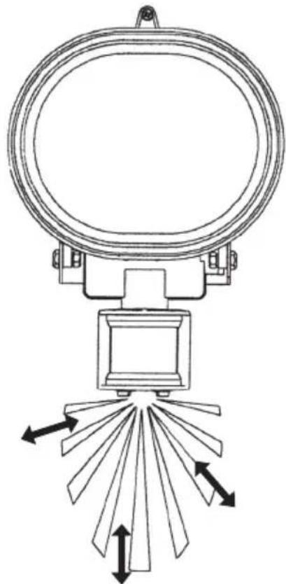
Fig. 1C
Installation
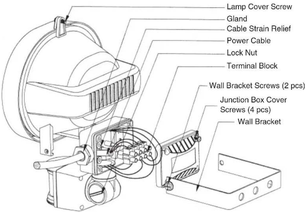
Fig. 2A
-
Important: Read the entire instruction manual before installation. The installation should be carried out by a qualified electrician and conform to current regulations.
-
Warning! Make sure that the power is turned off and that the fuse is removed before beginning any installation, change of light bulb or service.
-
Remove the wall bracket.
-
Using the bracket as a template, mark the position of the screw holes. Drill the holes in the wall where the light is to be mounted. Use suitable screws and wall plugs if necessary. The floodlight must be fixed securely. Mount the floodlight horizontally ( ± 4° ) (Fig. 3A).
-
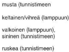
Remove the cover of the junction box, remove the cable gland and strain relief, feed in the power cable (3G 0.75) through the gland and rubber grommet. Connect the three wires of the cable to the terminal block (Fig. 2B).

Fig. 2B
-
Replace the terminal block, cable strain relief, cable gland and cover. Tighten the screws.
-
Undo the screws in the lamp cover and open it. Insert a light bulb between the spring-loaded holders. Close the lamp cover and tighten the screws.
Bear this in mind when changing light bulbs: Let the bulb cool before removing it, do not touch it with your fingers and make sure that all the lamp cover seals are intact.
- Fix the light to the wall bracket; tighten all screws and lock nuts. Position the floodlight in the desired place.
- Replace the fuse and adjust the light pattern.
Important! Undo lock nuts and screws before adjusting the angle of the light.
Warning: This light must NOT be directed at flammable surfaces (Fig. 3B,C).

Fig. 3A Fig. 3B Fig. 3C
Controls
- Operating time after activation the illumination time can be adjusted from (10±5 seconds) to (4±1 minutes), this time is altered by turning the [TIME] dial + or -. Note! Each time the detector senses a movement the operating time starts again.
- The light sensitivity needed for activation is measured by a photocell which differentiates between light and dark. Adjust it by turning the [LUX] dial from Sun to Moon. Sun is used during the day until nightfall; Moon is only used at night, in the dark.
- The motion sensitivity is controlled by the [SENS] dial, which alters the distance needed between the sensor and the motion in order to activate the light. Turn the dial towards the (+) to increase the distance needed, and the opposite way to lessen the distance needed to activate the light.

Setting the motion detector (Fig.4)
- Set the [LUX] dial to Sun, let the sensor stabilise for half a minute, make sure that the [TIME] dial is set on minimum (-). The floodlight will now activate for 30 seconds (this will happen within 1 minute).
- Point the sensor towards the area you wish to scan.
- Ask a friend to pass through the detection zone, carefully adjust the angle of the sensor arm until the floodlight is activated by your friend (see Fig. 1B).
- Adjust the operating time using [TIME] until it is set to your wishes.
- If you just want the light to come on in the dark, adjust the light sensitivity by turning the [LUX] dial from Sun to Moon. If you want the light to come on at dusk, wait until the light level has fallen to the desired level and then slowly turn the [LUX] dial towards the Sun symbol whilst having a friend walk across the detection zone. Turn the dial until the floodlight comes on. This procedure sometimes needs to be repeated before the correct setting is found.
Important! When adjusting the angle of the floodlight, make sure that its housing does not come too close to the sensor, the heat from the light might interfere with the sensor. Wipe the lens of the sensor with a damp cloth a few times a year but never open the sensor casing it could be damaged and the guarantee would become void.
Technical specifications
Max. range: °12 metres at 180° scanning angle
Operating Time: (10 ±5 seconds) to (4±1 minutes)
Type of sensor: Infra-Red (PIR)
Mains supply: 230 V AC, 50 Hz
Power Consumption: 4 W (sensor alone)
Max power consumption: 500 W for RP500BW and 150 W for RP150BW
Protection Class: IP44 (approved for outdoor use)
Disposal
Follow local ordinances when disposing of this product. If you are unsure about how to dispose of this product contact your municipality.
Troubleshooting
| Problem Possible | cause Remedy | |
| The floodlight is not activated by movement in the detection zone. | Power cut, blown fuse, light switched off. | Check the connections, fuses, switches. |
| Blown bulb. Inspect, replace. | ||
| The area is too light. Alter the direction of the sensor, move the sensor. | ||
| The control dial/s is/are set wrong. | Adjust the angle of the sensor or adjust the control dial. | |
| The sensor is aimed wrong. | Alter the direction of the sensor or adjust it. | |
| The floodlight comes on for no reason. | Heat from the floodlight housing is activating the sensor. | Adjust it. The min.distance between the floodlight and the sensor must be 40 mm. |
| Heat sources, lighting or cars are activating the sensor. | Direct the sensor head away from the sources of interference. | |
| Wild animals/birds, pets activating the sensor. | Changing the direction of the sensor head can help. | |
| Interference from other machinery on the same phase. | Try this: Replace blown fuse, replace fluorescent tube and/or reactor and starter. | |
| Reflections from swimming pool or other reflecting surface. | Point the sensor in another direction. | |
| The floodlight does not go off. | Lights all the time. Pointing the sensor in another direction might help. | |
| Lights too long. Reduce the setting using the [TIME] dial. | ||
| The floodlight comes on during the day. | The [LUX] dial is set on daylight (Sun). | Adjust the [LUX] setting and test it. |
Fig. 1B

Fig. 1C
Installation

Svart (till sensor)
Fig. 1B
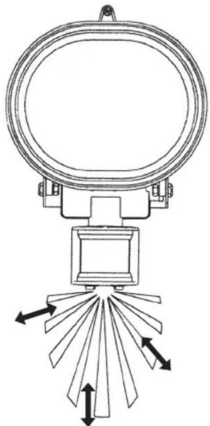
Fig. 1C
Installasjon

Fig. 2
+/-4 grader Mindst 90 grader Mindst 1 m

Fig. 3B Fig. 3C
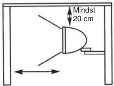
Fig. 3A
Innstillingsknapper
Kuva 1B

Kuva 1C
Asennus

For consumer contact, please visit www.clasohlson.co.uk and click on customer service.
INTERNET www.clasohlson.co.uk

Brand : Cotech
Model : 32-1508
Category : Lighting