
PLG150-AP - Synthesizer YAMAHA - Free user manual and instructions
Find the device manual for free PLG150-AP YAMAHA in PDF.

| Product Type | Synthesizer plug-in card for MSPS/XG system |
| Brand | YAMAHA |
| Model | PLG150-AP |
| Polyphony | 64 notes (monophonic voice) |
| Number of voices | 32 preset voices (AP-XG/A, AP-XG/B, Presets) |
| Sound generator | AWM2 (Advanced Wave Memory 2) |
| Built-in effects | Reverb, Chorus, Insertion, two-band EQ |
| Main functions | Acoustic piano simulation, sustain pedal, tonal stretch, PF mode, 4 effect blocks |
| Interface | Plug-in connector (card) |
| Power supply | Powered by host device |
| Compatibility | MSPS devices (MOTIF, S90, MU128) and XG Plug-in System (SW1000XG/P) |
| Maintenance and cleaning | Avoid dust, humidity, extreme heat; discharge static electricity before handling |
| Safety | Do not touch circuits, disconnect before installation, avoid short circuits |
| Installation instructions | Refer to the host device manual for physical installation |
| Included items | PLG150-AP card, user manual, CD-ROM, MSPS sticker |
| Technical specifications | Subject to change without notice |
Frequently Asked Questions - PLG150-AP YAMAHA
User questions about PLG150-AP YAMAHA
0 question about this device. Answer the ones you know or ask your own.
Ask a new question about this device
Download the instructions for your Synthesizer in PDF format for free! Find your manual PLG150-AP - YAMAHA and take your electronic device back in hand. On this page are published all the documents necessary for the use of your device. PLG150-AP by YAMAHA.
USER MANUAL PLG150-AP YAMAHA
- Please keep this manual in a safe place for future reference.

WARNING
Always follow the basic precautions listed below to avoid the possibility of serious injury or even death from electrical shock, short-circuiting, damages, fire or other hazards. These precautions include, but are not limited to, the following:
-
When holding the plug-in board, do not touch the inside area of the circuit board or apply excessive pressure to the board, and be sure to protect the board from contact with water or other liquids.
-
Before installing the plug-in board onto a tone generator/sound card, unplug the power connector of your computer.

CAUTION
Always follow the basic precautions listed below to avoid the possibility of physical injury to you or others, or damage to the instrument or other property. These precautions include, but are not limited to, the following:
- Before handling the plug-in board, be sure to touch a metal surface to discharge any static electricity which may be in your body.
-
Before connecting the instrument to other electronic components, turn off the power for all components. Before turning the power on or off for all components, set all volume levels to minimum. Also, be sure to set the volumes of all components at their minimum levels and gradually raise the volume controls while playing the instrument to set the desired listening level.
-
Do not expose the device to excessive dust or vibrations, or extreme cold or heat (such as in direct sunlight, near a heater, or in a car during the day) to prevent the possibility of damage to the internal components.
- Do not use the instrument in the vicinity of a TV, radio, stereo equipment, mobile phone, or other electric devices. Otherwise, the instrument, TV, or radio may generate noise.
- Do not operate the instrument for a long period of time at a high or uncomfortable volume level, since this can cause permanent hearing loss. If you experience any hearing loss or ringing in the ears, consult a physician.
Yamaha cannot be held responsible for damage caused by improper use or modifications to the device, or data that is lost or destroyed.
- The company names and product names in this Owner's Manual are the trademarks or registered trademarks of their respective companies.
- The screens as illustrated in this owner's manual are for instructional purposes only, and may appear somewhat different from the ones of your instrument.
Congratulations and thank you for purchasing the Yamaha PLG150-AP Piano Plug-in Board!
The PLG150-AP is a custom tone generator dedicated for piano voices and designed for use with a variety of Yamaha electronic musical instruments. It provides a wide variety of exceptionally high-quality, authentic acoustic piano sounds, as well as an assortment of unusual effect-processed piano sounds. The PLG150-AP can be installed to and integrated with instruments of the Modular Synthesis Plug-in System (including the S90, MOTIF and MOTIF ES). It can also be used seamlessly with the MU128 Tone Generator (as well as other MU-series instruments and the SW1000XG PCI Audio/MIDI Board).
To install your PLG150-AP correctly and to ensure full enjoyment of its sophisticated functions, be sure to read this manual very carefully. When finished, keep the manual in a secure and convenient place for future reference.
SPECIAL NOTICE
This product incorporates and bundles computer programs and contents in which Yamaha owns copyrights or with respect to which it has license to use others' copyrights. Such copyrighted materials include, without limitation, all computer software, MIDI files, WAVE data and sound recordings. Any unauthorized use of such programs and contents outside of personal use is not permitted under relevant laws.
- Unauthorized copying of copyrighted software for purposes other than the purchaser's personal use is prohibited.
MODULARSYNTHESIS PLUG-INSYSTEM
About the Modular Synthesis Plug-in System
The Yamaha Modular Synthesis Plug-in System offers powerful expansion and upgrade capabilities for Modular Synthesis-Plug-in-compatible synthesizers, tone generators and sound cards. This enables you to easily and effectively take advantage of the latest and most sophisticated synthesizer and effects technology, allowing you to keep pace with the rapid and multifaceted advances in modern music production.

About the XG Plug-in System
The Yamaha XG Plug-in System offers powerful expansion and upgrade capabilities for XG-Plug-in-compatible tone generators and sound cards. This enables you to easily and effectively take advantage of the latest and most sophisticated synthesizer and effects technology, allowing you to keep pace with the rapid and multi-faceted advances in modern music production.
Overview of the PLG150-AP 5
Main Features of the PLG150-AP. 5
Installing the PLG150-AP 5
Included Items 5
Required and Recommended Items 6
Specifications. 6
About the Included CD-ROM 7
PLG150-AP Structure 9
Selecting AP Voices
(Modular Synthesis Plug-in System) 10
Editing the AP Native Part Parameters
(Modular Synthesis Plug-in System) 11
Selecting/Editing the AP System Parameters
(Modular Synthesis Plug-in System) 12
Selecting AP Voices
(XG Plug-in System) 13
Editing the AP Native Part Parameters
(XG Plug-in System) 15
Selecting/Editing the AP System Parameters
(XG Plug-in System) 16
Parameters 17
AP Native Part Parameters 17
AP System Parameters 19
Appendix 20
Voice List 20
Parameter List (XG / Modular Synthesis Plug-in System) 22
MIDI Data Format 23
MIDI Implementation Chart 30
Important notice for the SW1000XG users 33
Main Features of the PLG150-AP
- Once connected and installed, the PLG150-AP becomes a seamless additional sound source for the host tone generator or synthesizer — providing a total of 32 acoustic piano voices, which can be edited from the panel of the host device. The PLG150-AP can be easily installed to any device compatible with the Modular Synthesis Plug-in System or the XG Plug-in System.
- A single PLG150-AP Plug-in Board functions as one part for the host device, providing up to 64 different voices (in mono sampling), and several boards can be installed to the same host device.
- Thanks to the built-in effect processing power, the PLG150-AP has four separate effect blocks — Reverb, Chorus, Insertion and two-band EQ — that can be applied to each voice.
- The PLG150-AP precisely simulates the actual acoustic behavior and motion sound when using the damper pedal.
- The PLG150-AP features voices with stretch tuning — the same kind of tuning as used on an actual acoustic piano.
Stretch tuning is widely used in the piano tuning profession, recognizing the phenomenon of human hearing by which higher notes sound slightly flat, even when perfectly in tune. Stretch tuning progressively raises the pitch of higher notes and decreases that of lower notes. Compared to precise equal temperament, the overall effect is greater tonal brilliance and a full, rich sound when playing open voiced chords.
Installing the PLG150-AP
For detailed instructions on installing the PLG150-AP, refer to the owner's manual of the Plug-in-compatible "mother" device (e.g., MOTIF series, S series, MU series, etc.).
Included Items
The following items have been included in the package of your new PLG150-AP.
Please make sure that you have them all before starting to setup and use the instrument. If an item is missing, contact the store or dealer from which you purchased the PLG150-AP.
- PLG150-AP Plug-in Board
- PLG150-AP Owner's Manual (this book)
- CD-ROM
- MSPS sticker
Required and Recommended Items
In addition to the included items listed above, you should also have the following:
- Synthesizer/Tone Generator/Sound Card Compatible with the Modular Synthesis or XG Plug-in Systems
In order to use the PLG150-AP, you'll need a synthesizer, tone generator or sound card that is compatible with the Modular Synthesis Plug-in System or the XG Plug-in System. Compatible instruments include the MOTIF ES, S90, and the MU128. The synthesizer/tone generator/sound card should also have an available slot or space for installing the PLG150-AP.
Specifications
Tone Generation System : AWM2 (Advanced Wave Memory 2)
Polyphony : 64 (when using mono-sampled voices)
Number of voices : 32 voices (AP-XG/A, AP-XG/B, Preset)
Interface : Plug-in connector
Effects: Reverb, Chorus, Insertion, 2-Band EQ
Dimensions (W x H x D): 138.5 x 89.0 x 8.5mm
Weight: 72g
Included Items : Owner's Manual, CD-ROM, MSPS sticker
- Specifications subject to change without notice.

- Noise may be generated when you assign the "AMod Depth" parameter to the controller and vary the controller during playback.
About the Included CD-ROM
The included CD-ROM contains demonstration songs in SMF (Standard MIDI File) format and audio data, and Plug-in Voice data for MSPS (Modular Synthesis Plug-in System) compatible instruments to which the PLG150-AP has been installed.
You can play back the audio data from an audio CD player (or a CD drive on your computer.)
Using an Audio CD Player

Never attempt to play back track 1 on an audio CD player.
Doing so may damage your hearing as well as your CD player/audio speakers.
Track 1: SMF data of the demonstration songs; do NOT attempt to play back this track.
Tracks 2-4: Demonstration songs recorded with the PLG150-AP
The included CD-ROM contains the following data.
■ Demonstration Songs
The included CD-ROM contains demo songs that showcase the sounds of the PLG150-AP. The demo songs are provided in both SMF format and as audio data.
You can play back the SMF data using a sequencer and the audio data from an audio CD player (or a CD drive on your computer.)
Before Playing Back the Demonstration songs
- For Modular Synthesis Plug-in System Users
Add the Plug-in Voice data to the mother device (page 8), then select the Bank to which the Plug-in Voices were added (e.g., Plug-in User Voice Bank). In addition, set the MIDI receive channel to "1."
- For XG Plug-in System Users
Set the Sound Module Mode to "XG", then set the tone generator to sound the voice of Preset Bank (MSB = 32, LSB = 1). In addition, set the MIDI receive channel to "1."
Plug-in Voice Data (for Modular Synthesis Plug-in System only)
This is Plug-in voice data, featuring a total of 64 voices that were created using the PLG150-AP Preset voices (Board Voices). A Plug-in Voice is a Board Voice that has been processed using the parameters in the synthesizer or tone generator. If you transfer this data via bulk dump to a synthesizer or tone generator, the Plug-in Voice is added to the User Voice Bank in the Plug-in Bank of the synthesizer or tone generator.
The Plug-in Voice data in the CD-ROM are grouped into the following three folders. Select the appropriate data in the folder corresponding to your particular synthesizer.
-S80_CS6X" folder (for CS6x, CS6R, S30, S80)
-S90MOTIF' folder (for S90, MOTIF, MOTIF-RACK)
-MOTIF-ES" folder (for MOTIF ES)
How to Add to Plug-in Voice Data to a Synthesizer or Tone Generator
1 Connect a computer to your synthesizer or tone generator using a MIDI or USB cable.
2 Start up the sequencer software.
3 If the PLG150-AP has been installed to the PLG1 slot, select the file "PLGV1.MID"; for slots PLG 2 and PLG 3, select files "PLGV2.MID" and "**PLGV3.MID," respectively. For details, see the owner's manual for the sequencer software you are using.
4 The Plug-in Voice data is automatically transferred via bulk dump to the synthesizer or tone generator.
5 When playback of the data reaches the end and the synthesizer or tone generator can be operated normally, setup is complete.
NOTE
- While the synthesizer or tone generator is receiving bulk data, do not turn off the device or sequencer, or disconnect the cable.
- The characters represented by ^** above differ depending on the folder.
- Before playing back the Plug-in Voice data, set the synthesizer or tone generator to allow reception of bulk data (set the "RcvBulk" parameter to on).
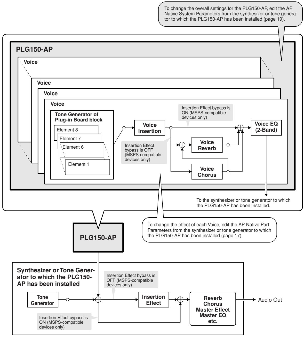
The following illustration shows the structure of PLG150-AP.
NOTE
For Modular Synthesis Plug-in System Users
- When the Insertion effect of the mother device is bypassed, the Voice Reverb and Voice Chorus of the PLG150-AP are also bypassed simultaneously. However, when your mother device has an effect bypass on/off parameter (e.g., "PLG-EF" parameter), set the function to on. If the parameter is off, the effect of PLG150-AP will not be bypassed.
- The Voice Insertion and Voice EQ of the PLG150-AP cannot be bypassed.
(Modular Synthesis Plug-in System)
When the PLG150-AP is installed to a synthesizer compatible with the Modular Synthesis Plug-in System, the AP voices can be selected in the same way as the internal voices of the synthesizer.

- The example displays used in the following explanations are all taken from the MOTIF ES.
1 Enter The Voice Play mode.
Press the [VOICE] button.
2 Select a Plug-in Voice bank.
Press one of the [PLG1] - [PLG3] buttons corresponding to the slot to which the PLG150-AP has been installed.

- The example displays here may differ from the actual ones that appear on your instrument.
3 Select a Group.
Press any of the GROUP [A] - [D] buttons.
4 Select a Voice.
Press any of the NUMBER [1] - [16] buttons.
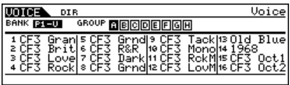
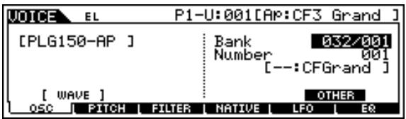
5 When selecting a bank in PLG150-AP (the MSB/LSB of preset bank (board voice) or User Voice bank), press the [F2] BANK button, then select a bank.
![YAMAHA PLG150-AP - When selecting a bank in PLG150-AP (the MSB/LSB of preset bank (board voice) or User Voice bank), press the [F2] BANK button, then select a bank. - 1](/content/2024/12/114781/images/b57246814a422b9c56369fea96c6a430c40c8c2dfb9c944bdffd97887987b15b.jpg)
Next, select a voice following steps 3 and 4 above.
![YAMAHA PLG150-AP - When selecting a bank in PLG150-AP (the MSB/LSB of preset bank (board voice) or User Voice bank), press the [F2] BANK button, then select a bank. - 2](/content/2024/12/114781/images/9918035370dc64d73f3f0c7cee1eec9c83399b4c82f8bae3551f50491cc20deb.jpg)
- The bulk-dumped plug-in voice data is saved in the User Voice Bank (PLG1USR).
For a list of the available banks and their MSB/LSB values, refer to the "Voice List" (page 20).
(Modular Synthesis Plug-in System)
The following explanations show how to edit the AP native part parameters when creating Plug-in Voices, using the MOTIF ES Control Synthesizer as an example. Voices created on the PLG150-AP are called Board Voices.
On MSPS / XG Plug-in System-compatible devices, you can edit the Board Voices using a variety of parameter settings, such as effects or EQ (AP native parameters).
On MSPS-compatible devices, the entire Board Voice is edited as one element.
A Board Voice edited on the MSPS-compatible device is called a Plug-in Voice.
For information about how to save Plug-in Voices, refer to the owner's manual of your MSPS-compatible device.

- Keep in mind that the parameter values and settings below represent offsets of the actual voice settings. This means that adjustments made to the parameters may not make much change in the actual sound, depending on the original settings of the voice. For parameter values, a setting of "0" results in no change, while positive and negative values increase and decrease the value respectively.
1 Select the desired AP voice, as described in "Selecting AP Voices" on page 10.
2 Enter the Voice Edit mode.
Press the [EDIT] button.
3 Select an element to be edited.
1) Press any one of the NUMBER buttons ([1] - [4]) to edit the element parameters.
2) Press the [F4] button to select the "NATIVE" element.
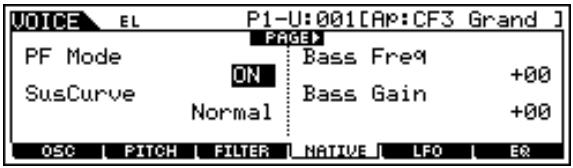
4 Select the desired parameter.
Use the cursor buttons to select the desired parameter.

- For a list of available parameters, see page 17.
5 Adjust the value or change the setting for the selected parameter.
Use the [INC/YES] and [DEC/NO] buttons or the data dial.
Selecting/Editing the AP System Parameters
(Modular Synthesis Plug-in System)
The parameters that apply to the entire system of the PLG150-AP are called AP native system parameters (page 19).
The parameters are included in the Utility mode of the MSPS-compatible device to which the PLG150-AP has been installed.
1 Press the UTILITY button.
The Utility Mode display appears.
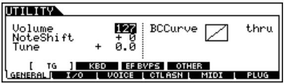
2 Press the [F6] (PLUG) button.
3 Press any of the [SF3] – [SF5] (NATIVE1 – NATIVE3) buttons corresponding to the slot to which the PLG150-AP has been installed.
4 Adjust the value or change the setting for the selected parameter.
Use the [INC/YES] and [DEC/NO] buttons or the data dial.
The PLG150-AP voices can be selected just like the voices of the XG tone generator. Keep in mind, though, that they can only be selected when the Sound Module Mode is set to XG or Performance. Also, the Part Assign parameter in the Utility mode (see below) must be set to the desired Part.
NOTE
- The example displays used in the following explanations are all taken from the MU128.
Enabling and Selecting AP Voices
1 Set the Sound Module Mode to "XG" or "PFM" (Performance).
Press the [MODE] button and use the [SELECT / ] buttons.
2 Set the Part Assign parameter to the desired Part number.
To do this:
1) Press the [UTIL] button.

2) Select the "PLUGIN" menu (with the [SELECT ] button) and press [ENTER].

3) Select the "PLG150-AP" menu if necessary (with the [SELECT ] buttons), and press [ENTER]. The Part Assign menu appears.
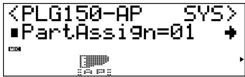
4) Use the [VALUE -/+] buttons or dial to change the Part number.
The Part Assign range for the XG mode is 1 - 16 and "off"; for the Performance mode, it is 1 - 4 and "off."
Press the [EXIT] button to return to the Play mode.
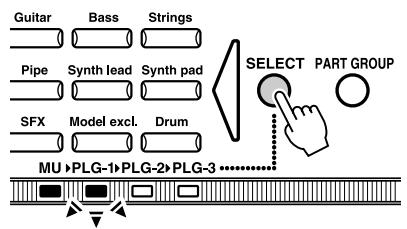
3 Enable the PLG150-AP board for the desired Part.
First, make sure that the appropriate Part is selected (using the [PART -/+] buttons), then press the [SELECT] button. The icon of the selected board appears in the display and the corresponding LED at the bottom of the panel (PLG-1, -2, or -3) flashes briefly.
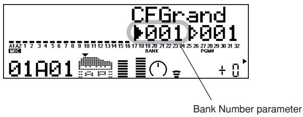
4 Select the desired bank number.
Move the cursor to the Bank Number parameter with the [SELECT / ] buttons and use the [VALUE -/+] buttons to select the desired bank.
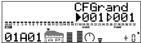
5 Select the desired voice number.
Move the cursor to the Voice (Program) Number parameter with the [SELECT / ] buttons and use the [VALUE -/+] buttons to select the desired voice.

-
Voice (and Voice banks) can also be selected by using the Voice Category buttons.
-
AP-XG/A : 106
- AP-XG/B : 106
- Preset :001

AP-XG/A

AP-XG/B

Preset
Alternatively, you can select voices from a connected MIDI keyboard, or from sequencing software on a connected computer.
For a list of available voices and their bank/voice numbers, see page 20.
Any of the AP voices can be freely edited from the front panel with the AP Native Part parameters. Keep in mind that changing the Part parameters does not permanently affect the original voice settings. The edits that you make here temporarily change the settings of the currently selected voice. When you select a different voice for the Part, the settings are applied to the newly selected voice.
NOTE
- The parameter values and settings below represent offsets of the actual voice settings. This means that adjustments made to the parameters may not make much change in the actual sound, depending on the original settings of the voice. For parameter values, a setting of "0" results in no change, while positive and negative values increase and decrease the value respectively.
- The Part parameter settings cannot be saved in Multi Play mode. If you wish to save your Part parameter edits, do it from the Performance mode.
- The example displays used in the following explanations are all taken from the MU128.
1 Select the Part having the AP voice, then select the desired voice.
Select the appropriate Part with the [PART -/+] buttons, then, with the cursor at the Voice Number parameter, select the desired voice.
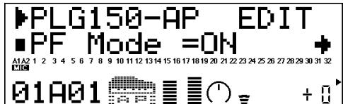
2 Press the [EDIT] button to enter the Edit mode.
![YAMAHA PLG150-AP - Press the [EDIT] button to enter the Edit mode. - 1](/content/2024/12/114781/images/daca5eab7f8f729111c8d283b7cb3a88400761fb24a2f70b301d0a41b026273a.jpg)
3 Select the "PLUGIN" menu.
Use the [SELECT ] button, then press the [ENTER] button. The PLG150-AP Edit menu appears.
4 Select the desired parameter.
Use the [SELECT / ] buttons.
5 Adjust the value or change the setting for the selected parameter.
Use the [VALUE + / - ] buttons.
6 Return to the main Play display.
Press the [EXIT] button several times, or press the [PLAY] button once.
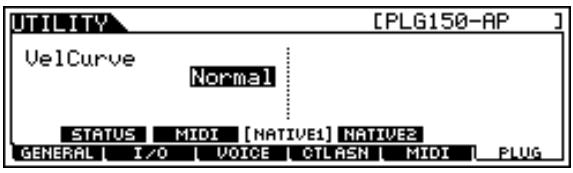
Selecting/Editing the AP System Parameters
(XG Plug-in System)
The parameters that apply to the entire system of the PLG150-AP are called the AP native system parameters (page 19).
The parameters are included in the Utility mode menu of the XG tone generator to which the PLG150-AP has been installed.

- The example displays used in the following explanations are all taken from the MU128.
1 Press the [UTIL] button.
The Utility mode menu appears.
![YAMAHA PLG150-AP - Press the [UTIL] button. - 1](/content/2024/12/114781/images/b8bfd866f2b4b76b0df0a824a0f44192b18583bdd0ef10c898b7fe397dea6b5b.jpg)
2 Select the "PLUGIN" menu.
Use the [SELECT ] button to highlight "PLUGIN," then press the [ENTER] button.
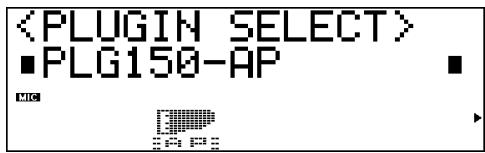
3 Select the PLG150-AP board.
If the PLG150-AP board is the only one installed, "PLG150-AP" is already displayed and can be selected by pressing the [ENTER] button. If additional boards have been installed to the tone generator, you may need to select "PLG150-AP." To do this, first use the [SELECT / ] buttons, then press [ENTER].
The System parameter menu for the PLG150-AP appears.
4 Select the desired parameter.
Use the [SELECT / ] buttons.
5 Adjust the value or change the setting for the selected parameter.
Use the [VALUE + / - ] buttons.
6 Return to the main Play display.
Press the [EXIT] button several times, or press the [PLAY] button once.
AP Native Part Parameters (PLG150-AP NATIVE MULTI PART (page 29))
Keep in mind that the parameter values and settings represent offsets of the actual voice settings. This means that the actual sound that results from the settings made here depends on the original settings of the voice.
Also keep in mind that these are "Part" parameters and as such, are temporary; they simply alter or offset the settings of the currently selected voice. The original voice settings are permanently maintained in memory.
For parameter values, a setting of "0" results in no change, while positive and negative values increase and decrease the value respectively.
Let's look at a specific example. If the original Bass Frequency parameter of the selected voice is set to 100, and you set the Bass Frequency (below) to “-25,” the actual Bass Frequency will become “75.” If you set it to “+10,” the value will become “110.” Naturally, this also means that the parameter value cannot be increased or decreased beyond its maximum or minimum values. In our example, Bass Frequency values higher than “+27” have no effect on the sound, since the actual range is 0 – 127.
NOTE
- Depending on the selected voice and the particular parameter being edited, the sound or actual parameter value of certain voices may change very little or not at all, even when the parameter value is changed drastically.
- For Modular Synthesis Plug-in System compatible devices, the voices you edit/create can be stored to the device as PLG voices. For details on storing voices, refer to the owner's manual of your Modular Synthesis Plug-in System compatible instrument.
PF Mode
Settings: ON, OFF
This determines whether the PF (Piano) Mode is on or off. When this is set to "ON" and damper (sustain) pedal messages are received, the PLG150-AP simulates the sound of a damper pedal.
If monophonic playback has been selected on your synthesizer, this parameter cannot be set.
SusCurve (Sustain Curve)
Settings: Normal, Step ("***": not available)
This determines how the voices respond to damper (sustain) pedal messages. When this is set to "Normal," the PLG150-AP simulates the actual damper pedal action of an acoustic piano, giving you continuous control over sustain. When this is set to "Step," sustain is simply turned on or off in response to damper pedal messages.
If "PF Mode" (above) has been set to OFF or monophonic playback has been selected on your synthesizer, this parameter cannot be set.
Bass Freq (Bass Frequency)
Range: -64 - +00 - +63
This determines the frequency which is boosted or cut (in the Bass Gain parameter below) for each Part.
Bass Gain
Range: -64 - +00 - +63
This determines the level of the selected frequency (in "Bass Freq" above). Positive values boost the level of the selected frequency and negative values attenuate it.
Treble Freq (Treble Frequency)
Range: -64 - +00 - +63
This determines the frequency which is boosted or cut (in the Treble Gain parameter below) for each Part.
Treble Gain
Range: -64 - +00 - +63
This determines the level of the selected frequency (in "Treble Freq" above). Positive values boost the level of the selected frequency and negative values attenuate it.
■ REV Send (Reverb Send)
Range: -127 +127 ("**": not available)
This determines the amount of voice signal that is sent to the PLG150-AP's built-in Reverb effect.
CHO Send (Chorus Send)
Range: -127 - +127 ("**": not available)
This determines the amount of voice signal that is sent to the PLG150-AP's built-in Chorus effect.
INS LFOFreq (Insertion LFO Frequency)
Range: -127 - +127 ("****": not available)
This determines the frequency of LFO modulation for the PLG150-AP's built-in Insertion effect.
INS LFODpt (Insertion LFO Depth)
Range: -127 +127 ("**": not available)
This determines the depth of LFO modulation for the PLG150-AP's built-in Insertion effect.
INS Feedback (Insertion Feedback Level)
Range: -64 + +63 ("***": not available)
This determines the feedback level for the PLG150-AP's built-in Insertion effect.
INS DryWet (Insertion Dry/Wet Balance)
Range: -127 + 127 ("**": not available)
This determines the balance between the direct, unprocessed signal (dry) and the Insertion-processed sound (wet).
INS Offset (Insertion Offset)
Range: -127 - +127 ("**": not available)
This parameter is used to change one specific parameter of the effect; the particular parameter depends on the effect type.
INS Drive (Insertion Drive)
Range: -127 - +127 ("**": not available)
This determines the amount of distortion overdrive for the PLG150-AP's built-in Insertion effect.
INS ClpCrv (Insertion Clipping Curve)
Range: -127 - +127 ("**": not available)
This determines the amount of distortion "edge" for the PLG150-AP's built-in Insertion effect. Higher values result in harder edged distortion.
INS Delay (Insertion Delay Time)
Range: -7149 - +7149 (****: not available)
This determines the delay time for the PLG150-AP's built-in Insertion effect.

- Keep in mind that these parameters are offset controls; the actual resulting effect sound will differ from voice to voice. If the currently selected voice does not have any effect or uses an effect type not corresponding to this parameter, the parameter is unavailable and is indicated by asterisks ("****") in the display.
- Whether this Insertion effect parameter is available or not depends on the selected voice and its preassigned Insertion effect types. (For details on the effect types and parameters for each voice, see the Preset Voice Bank on page 20.)
AP System Parameters (PLG150-AP NATIVE SYSTEM (page 29))
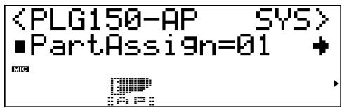
Part Assign
Settings: 01-16, off
This determines the Part to which the PLG150-AP voice is assigned. If a Part is not properly assigned here, none of the PLG150-AP voices can be selected for the Part. (This applies to XG Plug-in System compatible "mother" devices.)

- The PLG150-AP voices can only be assigned to a single Part.
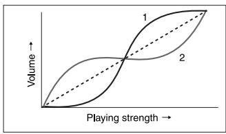
VelCurve (Velocity Curve)
Settings: Normal, Soft1, Soft2, Soft3, Hard1, Hard2, Cross1, Cross2
This function lets you set how the volume of the PLG150-AP's Voices respond to your playing touch (velocity). Eight different Velocity Curve settings (or curves) are available, letting you tailor the response to your own preference.
- The Normal setting provides standard touch response.
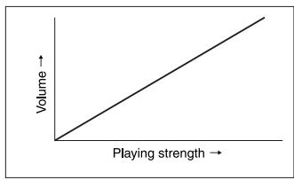
- Soft 1 to 3 allow you to produce a reasonably high volume with a soft, light touch (low velocities).
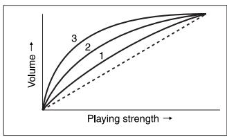
- Hard 1 and 2 produce high volume only with a hard, strong touch (high velocities).
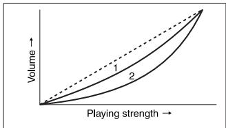
- Cross 1 and 2 are "mirror image" curves, designed to be used together with different voices in a layer to produce a velocity crossfade effect. As shown in the illustration, the two curves complement each other in a way that allows the Cross 2 applied voice to sound at soft velocities, while the Cross 1 voice sounds at high velocities.
VORSIGHTSMASSNAHMEN
Bass Freq (Bass Frequency, Bassfrequenz)
INS LFOFreq (Insertion LFO Frequency)
INS LFODpt (Insertion LFO Depth)
INS Feedback (Insertion Feedback Level)
INS DryWet (Insertion Dry/Wet Balance)
INS Drive (Insertion Drive)
Effects : Reverb, Chorus, Insertion, EQ 2 bandes
Dimensions (L x H x P) : 138,5 x 89,0 x 8,5 mm
Poids: 72g
Preset Voice Bank (Bank Select MSB = 32, Bank Select LSB = 1)
| PGM# | Name | E | Available Native Part Parameters | VOICE INSERTION EFFECT TYPE | ||||||||||
| REVERB SEND 0....= [dB] | CHORUS SEND 0....= [dB] | INSERTION LFO FREQUENCY 0.00 ... 39.7[Hz] | INSERTION LFO DEPTH LEVEL 0 ... 127 | INSERTION FEEBACK LEVEL -63 ... +63 | INSERTION DRY/WET LEVEL D63-W ... D=W ... D=W63 | INSERTION OFFSET (0.0 ... 50.0[ms]) | INSERTION DRIVE 0 ... 127 | INSERTION CLIP CURVE Mild ... Sharp | INSERTION DELAY TIME | |||||
| 1 | CFGrand | 2 | - | - | - | - | - | - | - | - | - | - | 2Band EQ | |
| 2 | CFBrite | 2 | - | - | - | - | - | - | - | - | - | - | 2Band EQ | |
| 3 | CFLove | 2 | - | - | - | - | - | - | - | - | - | - | 2Band EQ | |
| 4 | CFRock | 2 | - | - | - | - | - | - | - | - | - | - | 2Band EQ | |
| 5 | CFGrnd2 | 2 | - | - | - | - | - | - | - | - | - | - | 2Band EQ | |
| 6 | CFR&R | 2 | - | - | - | - | - | - | - | - | - | - | 2Band EQ | |
| 7 | CFDark | 2 | - | - | - | - | - | - | - | - | - | - | 2Band EQ | |
| 8 | CFGrnd3 | 2 | - | - | - | - | - | - | - | - | - | - | 2Band EQ | |
| 9 | CFTack1 | 2 | - | - | - | - | - | - | - | - | - | - | 2Band EQ | |
| 10 | CFMono | 1 | - | - | - | - | - | - | - | - | - | - | 3Band EQ | |
| 11 | CFRkMn | 1 | - | - | - | - | - | - | - | - | - | - | 2Band EQ | |
| 12 | CFLovMn | 1 | - | - | - | - | - | - | - | - | - | - | 3Band EQ | |
| 13 | OldBlue | 2 | - | - | - | - | - | - | - | - | - | - | Thru | |
| 14 | 1968 | 1 | - | - | - | - | - | X | - | X | X | - | Amp Simulator | |
| 15 | CFOct1 | 4 | - | - | - | - | - | - | - | - | - | - | 2Band EQ | |
| 16 | CFOct2 | 4 | - | - | - | - | - | - | - | - | - | - | 2Band EQ | |
| 17 | CFTack2 | 2 | - | - | - | - | - | - | - | - | - | - | 2Band EQ | |
| 18 | CFHonky | 2 | - | - | - | - | - | - | - | - | - | - | 2Band EQ | |
| 19 | CFHouse | 2 | - | - | - | - | - | - | - | - | - | - | 2Band EQ | |
| 20 | BndPass | 2 | - | X | - | - | - | - | - | - | - | - | 2Band EQ | |
| 21 | Squishy | 2 | - | - | - | - | X | X | - | - | X (0.1...715.0[ms]) | Delay L,R | ||
| 22 | 1960s | 2 | - | - | - | - | - | X | - | X | X | - | Overdrive | |
| 23 | Dulcim | 2 | X | X | - | - | - | - | - | - | - | - | 2Band EQ | |
| 24 | Reversd | 3 | - | X | - | - | - | X | - | X | X | - | Amp Simulator | |
| 25 | Engulf | 2 | - | X | - | - | - | X | - | X | X | - | Distortion | |
| 26 | Cycling | 4 | - | X | X | X | X | X | X | - | - | - | Chorus2 | |
| 27 | Harmony | 3 | - | X | - | - | X | X | - | - | - | X (0.1...715.0[ms]) | Delay L,C,R | |
| 28 | Haunted | 2 | - | X | - | - | X | X | - | - | - | X (0.1...715.0[ms]) | Delay L,C,R | |
| 29 | Drops | 2 | - | - | - | - | X | X | - | - | - | X (0.1...355.0[ms]) | Cross Delay | |
| 30 | S&H Pno | 2 | X | X | X | X | - | - | - | - | - | - | Auto Pan | |
| 31 | CQuencd | 2 | X | X | - | - | X | X | - | - | - | X (0.1...715.0[ms]) | Delay L,C,R | |
| 32 | InScape | 2 | X | X | - | - | X | X | - | - | - | X (0.1...715.0[ms]) | Delay L,C,R | |
| 33 | CFGrand* | 2 | - | - | - | - | - | - | - | - | - | - | 2Band EQ | |
| 34 | CFBrite* | 2 | - | - | - | - | - | - | - | - | - | - | 2Band EQ | |
| 35 | CFLove* | 2 | - | - | - | - | - | - | - | - | - | - | 2Band EQ | |
| 36 | CFRock* | 2 | - | - | - | - | - | - | - | - | - | - | 2Band EQ | |
| 37 | CFGrnd2* | 2 | - | - | - | - | - | - | - | - | - | - | 2Band EQ | |
| 38 | CFR&R* | 2 | - | - | - | - | - | - | - | - | - | - | 2Band EQ | |
| 39 | CFDark* | 2 | - | - | - | - | - | - | - | - | - | - | 2Band EQ | |
| 40 | CFGrnd3* | 2 | - | - | - | - | - | - | - | - | - | - | 2Band EQ | |
| 41 | CFTack1* | 2 | - | - | - | - | - | - | - | - | - | - | 2Band EQ | |
| 42 | CFMono* | 1 | - | - | - | - | - | - | - | - | - | - | 3Band EQ | |
| 43 | CFRkMn* | 1 | - | - | - | - | - | - | - | - | - | - | 2Band EQ | |
| 44 | CFLovMn* | 1 | - | - | - | - | - | - | - | - | - | - | 3Band EQ | |
| 45 | OldBlue* | 2 | - | - | - | - | - | - | - | - | - | - | Thru | |
| 46 | 1968* | 1 | - | - | - | - | X | - | X | X | - | Amp Simulator | ||
| 47 | CFOct1* | 4 | - | - | - | - | - | - | - | - | - | - | 2Band EQ | |
| 48 | CFOct2* | 4 | - | - | - | - | - | - | - | - | - | - | 2Band EQ | |
| 49 | CFTack2* | 2 | - | - | - | - | - | - | - | - | - | - | 2Band EQ | |
| 50 | CFHonky* | 2 | - | - | - | - | - | - | - | - | - | - | 2Band EQ | |
| 51 | CFHouse* | 2 | - | - | - | - | - | - | - | - | - | - | 2Band EQ | |
| 52 | BndPass* | 2 | - | X | - | - | - | - | - | - | - | - | 2Band EQ | |
| 53 | Squishy* | 2 | - | - | - | - | X | X | - | - | X (0.1...715.0[ms]) | Delay L,R | ||
| 54 | 1960s* | 2 | - | - | - | - | X | X | - | X X | X | - | Overdrive | |
| 55 | Dulcim* | 2 | X | X | - | - | - | - | - | - | - | - | 2Band EQ | |
| 56 | Reversd* | 3 | - | X | - | - | X | X | - | X X | X | - | Amp Simulator | |
| 57 | Engulf* | 2 | - | X | - | - | X | X | - | X X | X | - | Distortion | |
| 58 | Cycling* | 4 | - | X | X | X | X | X | X | - | - | - | Chorus2 | |
| 59 | Harmony* | 3 | - | X | - | - | X | X | - | - | X (0.1...715.0[ms]) | Delay L,C,R | ||
| 60 | Haunted* | 2 | - | X | - | - | X | X | - | - | X (0.1...715.0[ms]) | Delay L,C,R | ||
| 61 | Drops* | 2 | - | - | - | - | X | X | - | - | - | X (0.1...355.0[ms]) | Cross Delay | |
| 62 | S&H Pno* | 2 | X | X | X | X | - | - | - | - | - | - | Auto Pan | |
| 63 | CQuencd* | 2 | X | X | - | - | X | X | - | - | - | X (0.1...715.0[ms]) | Delay L,C,R | |
| 64 | InScape* | 2 | X | X | - | - | X | X | - | - | - | X (0.1...715.0[ms]) | Delay L,C,R | |
X: available
E: Number of elements

Voices with names indicated by an asterisk (*) use conventional equal temperament tuning. Voices without an asterisk use stretch tuning.
XG Voice Map
AP-XG/A Bank
| Bank Select MSB | 80 | ||
| Bank Select LSB | 106 | ||
| Instrument Group | PGM# | Name | E |
| Piano | 1 | CFGrand | 2 |
| 2 | CFBrite | 2 | |
| 4 | CFHonky | 2 | |
E: Number of simultaneously sounding elements.

If the PLG150-AP is not installed, you cannot use the voices of this bank.
XG/B Bank
| Bank Select MSB | 96 | ||
| Bank Select LSB | 106 | ||
| Instrument Group | PGM# | Name | E |
| Piano | 1 | CFGrand | 2 |
| 2 | CFBrite | 2 | |
| 4 | CFHonky | 2 | |
E: Number of simultaneously sounding elements.

- If the PLG150-AP is not installed, internal voices similar to those above will be substituted.
- For information on the substitute voices, refer to the XG Voice List (MSB=0) of the XG Plug-in System "mother" device.
Plug-in Voice List (for Modular Synthesis Plug-in System-compatible instruments)
| PGM# | Name |
| 1 | CF3 Grand |
| 2 | CF3 Brite |
| 3 | CF3 Love |
| 4 | CF3 Rock |
| 5 | CF3 Grnd2 |
| 6 | CF3 R&R |
| 7 | CF3 Dark |
| 8 | CF3 Grnd3 |
| 9 | CF3 Tack1 |
| 10 | CF3 Mono |
| 11 | CF3 RckMn |
| 12 | CF3 LovMn |
| 13 | Old Blues |
| 14 | 1968 |
| 15 | CF3 Oct1 |
| 16 | CF3 Oct2 |
| PGM# | Name |
| 17 | CF3 Tack2 |
| 18 | CF3 Honky |
| 19 | CF3 House |
| 20 | BandPass |
| 21 | Squishy |
| 22 | 1960s |
| 23 | Dulcimer |
| 24 | Reversed |
| 25 | Engulf |
| 26 | Cycling |
| 27 | Harmony |
| 28 | Haunted |
| 29 | drops |
| 30 | S&H Piano |
| 31 | C-Quenced |
| 32 | In Space |
| PGM# | Name |
| 33 | CF3 Grand* |
| 34 | CF3 Brite* |
| 35 | CF3 Love* |
| 36 | CF3 Rock* |
| 37 | CF3 Grnd2* |
| 38 | CF3 R&R* |
| 39 | CF3 Dark* |
| 40 | CF3 Grnd3* |
| 41 | CF3 Tack1* |
| 42 | CF3 Mono* |
| 43 | CF3 RckMn* |
| 44 | CF3 LovMn* |
| 45 | Old Blues* |
| 46 | 1968* |
| 47 | CF3 Oct1* |
| 48 | CF3 Oct2* |
| PGM# | Name |
| 49 | CF3 Tack2* |
| 50 | CF3 Honky* |
| 51 | CF3 House* |
| 52 | BandPass* |
| 53 | Squishy* |
| 54 | 1960s* |
| 55 | Dulcimer* |
| 56 | Reversed* |
| 57 | Engulf* |
| 58 | Cycling* |
| 59 | Harmony* |
| 60 | Haunted* |
| 61 | drops* |
| 62 | S&H Piano* |
| 63 | C-Quenced* |
| 64 | In Space* |

- Voices with names indicated by an asterisk (*) use conventional equal temperament tuning.
- Voices without an asterisk use stretch tuning.
- To add the Plug-in Voices to the "mother" device, transmit the Plug-in Voice data to the device using the included CD-ROM (page 8).
Parameter List (XG / Modular Synthesis Plug-in System)
| Modular Synthesis Plug-in System | XG Plug-in System | (LCD of CS6x/CS6R/S30/S80/etc.) |
(Common Parameter)
| Parameter Name | Parameter Name | Group | Parameter |
| Volume | VOLUME | QED*Level | Vol |
| Pan | PAN | QED*Level | Pan |
| Reverb Send | REVERB SEND | QED*Level | RevSend |
| Chorus Send | CHORUS SEND | QED*Level | ChoSend |
| LPF Cutoff Frequency | LOW PASS FILTER CUTOFF FREQUENCY | QED*Filter | Cutoff |
| LPF Resonance | LOW PASS FILTER RESONANCE | QED*Filter | Reso |
| Attack Time | EG ATTACK TIME | QED*EG | Attack |
| Decay Time | EG DECAY TIME | QED*EG | Decay |
| Release Time | EG RELEASE TIME | QED*EG | Release |
| Pitch Bend Range | BEND PITCH CONTROL | CTL*Pitch | Pitch Bend |
| Portamento Switch | PORTAMENTO SWITCH | CTL*Pitch | Portamento |
| Portamento Time | PORTAMENTO TIME | CTL*Pitch | Time |
| Mono/Poly Mode | MONO/POLY MODE | GEN*Other | Mode |
| Same Note Number Key On Assign | SAME NOTE NUMBER KEY ON ASSIGN | GEN*Other | Assign |
(Element Parameter)
| Parameter Name | Parameter Name | Group | Parameter |
| Plug-in Board Voice Bank MSB | BANK SELECT MSB | PLG*Assign | Bank |
| Plug-in Board Voice Bank LSB | BANK SELECT LSB | PLG*Assign | Bank |
| Plug-in Board Voice Program Number | PROGRAM NUMBER | PLG*Assign | Number |
| Note Shift | NOTE SHIFT | PLG*Velocity | NoteSft |
| Velocity Sense Depth | VELOCITY SENSE DEPTH | PLG*Velocity | Depth |
| Velocity Sense Offset | VELOCITY SENSE OFFSET | PLG*Velocity | Offset |
| Pitch EG Initial Level | PITCH EG INITIAL LEVEL | PCH*PEG | InitLvl |
| Pitch EG Attack Time | PITCH EG ATTACK TIME | PCH*PEG | Attack |
| Pitch EG Release Level | PITCH EG RELEASE LEVEL | PCH*PEG | --Level |
| Pitch EG Release Time | PITCH EG RELEASE TIME | PCH*PEG | Release |
| LFO Rate | VIBRATO RATE | LFO Param | Speed |
| LFO Pitch Modulation Depth | VIBRATO DEPTH | LFO Param | PMod |
| LFO Delay | VIBRATO DELAY | LFO Param | Delay |
| HPF Cutoff Frequency | HIGH PASS FILTER CUTOFF FREQUENCY | QED*Filter | HPF |
| EQ Low Gain | EQ BASS GAIN | EQ*Param | LoGain |
| EQ High Gain | EQ TREBLE GAIN | EQ*Param | HiGain |
| EQ Low Frequency | EQ BASS FREQUENCY | EQ*Param | LoFreq |
| EQ High Frequency | EQ TREBLE FREQUENCY | EQ*Param | HiFreq |
| MW Filter Control | MW LOW PASS FILTER CONTROL | CTL*MW Control | Filter |
| MW LFO Pitch Modulation Depth | MW LFO PMOD深度 | CTL*MW Modulation | PMod |
| MW LFO Filter Modulation Depth | MW LFO FMOD深度 | CTL*MW Modulation | FMod |
| MW LFO Amplitude Modulation Depth | MW LFO AMOD深度 | CTL*MW Modulation | AMod |
| CAT Pitch Control | CAT PITCH CONTROL | CTL*AT Control | Pitch |
| CAT Filter Control | CAT LOW PASS FILTER CONTROL | CTL*AT Control | Filter |
| CAT LFO Pitch Modulation Depth | CAT LFO PMOD深度 | CTL*AT Modulation | PMod |
| CAT LFO Filter Modulation Depth | CAT LFO FMOD深度 | CTL*AT Modulation | FMod |
| CAT LFO Amplitude Modulation Depth | CAT LFO AMOD深度 | CTL*AT Modulation | AMod |
| AC1 Controller Number | AC1 CONTROLLER NUMBER | CTL*AC Control | Source |
| AC1 Filter Control | AC1 LOW PASS FILTER CONTROL | CTL*AC Control | Filter |
| AC1 LFO Pitch Modulation Depth | AC1 LFO PMOD深度 | CTL*AC Modulation | PMod |
| AC1 LFO Filter Modulation Depth | AC1 LFO FMOD深度 | CTL*AC Modulation | FMod |
| AC1 LFO Amplitude Modulation Depth | AC1 LFO AMOD深度 | CTL*AC Modulation | AMod |
1. Channel messages
1.1 Note on/note off
These messages convey keyboard performance data.
Range of note numbers received = C - 2 G8
Velocity range = 1 127 (Velocity is received only for note-on)
When the Multi Part parameter "Rcv NOTEMESSAGE" = OFF, that part will not receive these messages.
1.2 Control changes
These messages convey control operation information for volume or pan etc. Their functions are differentiated by the control number (Ctrl#).
If the Multi Part parameter Rcv CONTROL CHANGE = OFF, that part will not receive control changes.
1.2.1 Bank Select
This message selects the voice bank.
Control#
Parameter
Bank Select MSB
Bank Select LSB
Data Range
0...127
(32:Preset,80:AP-XG/A,96:AP-XG/B)
0...127
The Bank Select data will be processed only after a Program Change is received, and then voice bank will change at that time. If you wish to change the voice bank as well as the voice, you must transmit Bank Select and Program Change messages as a set, in the following order: Bank Select MSB, LSB, and Program Change.
1.2.2 Modulation
This message is used primarily to control the depth of vibrato, but the depth of the following 6 types of effect can be controlled. The effect of this message can be changed by the following parameters.
- Multi Part Parameter
1.MW PITCH CONTROL
2.MW FILTER CONTROL
3.MW AMPLITUDE CONTROL
4.MW LEO PMOD DEPTH
5.MWLFOFMODDEPTH
6.MWLFOAMODDEPTH
By default, an LFO Pitch Modulation (PMOD) effect will apply.
Control#
Parameter
Modulation
Data Range
0...127
If the Multi Part parameter Rcv MODULATION = OFF, that part will not receive Modulation.
1.2.3 Portamento Time
This message controls the degree of Portamento (see 1.2.9).
Control#
Parameter
Portamento Time
Data Range
0...127
When Portamento is ON, this regulates the speed of the pitch change. A value of 0 is the shortest Portamento time, and 127 is the longest Portamento time.
1.2.4 Data Entry
This message sets the value of the parameter which was specified by RPN (see 1.2.18) and NRPN (see 1.2.17).
Control#
Parameter
Data Entry MSB
Data Entry LSB
Data Range
0...127
0...127
1.2.5 Main Volume
This message controls the volume of each part. (It is used to adjust the volume balance between parts.)
Control#
Parameter
Main Volume
Data Range
0...127
When the Multi Part parameter Rcv VOLUME = OFF, that part will not receive Main Volume. With a value of 0 there will be no sound, and a value of 127 will produce the maximum volume.
This message is processed on the host device (e.g., MOTIF ES, MU128, etc.)
1.2.6 Panpot
This message controls the panning (stereo location) of each part.
Control#
Parameter
Pan
Data Range
0...64...127
When the Multi Part parameter Rcv PAN = OFF, that part will not receive Pan-pot. 0 is left, 64 is center, and 127 is right.
This message is processed on the host device (e.g., MOTIF ES, MU128, etc.)
1.2.7 Expression
This message controls expression for each part. It is used to create volume changes during a song.
Control#
Parameter
Expression
Data Range
0...127
If the Multi Part parameter Rcv EXPRESSION = OFF, that part will not receive Expression.
This message is processed on the host device (e.g., MOTIF ES, MU128, etc.)
1.2.8 Holdl
This message controls sustain pedal on/off.
Control#
Parameter
Data Range
64
Hold1
0...63,64...127
(OFF, ON)
When this is ON, currently-sounding notes will continue to sound even if note-off messages are received. If the Multi Part parameter Rcv HOLD1 = OFF, that part will not receive Holdl.
1.2.9 Portamento
This message controls Portamento pedal on/off.
Control#
Parameter
Portamento
Data Range
0...63,64...127
(OFF, ON)
When ON, Portamento produces a smooth glide connecting two notes of different pitch. The time over which the pitch changes is adjusted by Portamento Time (see 1.2.3). When the Multi Part Parameter MONO/POLY MODE = MONO, the tone will also change smoothly (legato) if Portamento = ON.
If the Multi Part parameter Rcv PORTAMENTO = OFF, that part will not receive Portamento.
1.2.10 Sostenuto
This message controls sostenuto pedal on/off.
Control#
Parameter
Sostenuto
Data Range
0...63,64...127
(OFF, ON)
If sostenuto is turned on while a note is sounding, that note will be sustained until sostenuto is turned OFF.
If the Multi Part parameter Rcv SOSTENUTO = OFF, that part will not receive Sostenuto.
1.2.11 Soft Pedal
This message controls soft pedal on/off.
Control#
Parameter
Soft Pedal
Data Range
0...63, 64...127
(OFF, ON)
When ON, the sound is soft.
If the Multi Part parameter Rcv SOFT PEDAL = OFF, that part will not receive the Soft Pedal.
1.2.12 Harmonic Content
This message adjusts the resonance of the filter that is specified for the sound.
Control#
Parameter
Harmonic Content
Data Range
0...64...127
(-64...0...+63)
Since this is a relative change parameter, it specifies an increase or decrease relative to 64. Higher values will produce a more distinctive sound.
For some sounds, the effective range may be less than the possible range of settings.
1.2.13 Release Time
This message adjusts the EG release time that was specified by the sound data.
Control#
Parameter
Release Time
Data Range
0...64...127
(-64...0...+63)
Since this is a relative change parameter, it specifies an increase or decrease relative to 64. Increasing this value will lengthen the release time that follows a note-off.
1.2.14 Attack Time
This message adjusts the EG attack time that was specified by the sound data.
Control#
Parameter
Data Range
73
Attack Time
0...64...127
(-64...0...+63)
Since this is a relative change parameter, it specifies an increase or decrease relative to 64. Increasing this value will make the attack more gradual, and decreasing this value will make the attack sharper.
1.2.15 Brightness
This message adjusts the cutoff frequency of the low pass filter specified by the sound data.
Control#
Parameter
Data Range
74
Brightness
0..64...127
(-64...0...+63)
Since this is a relative change parameter, it specifies an increase or decrease relative to 64. Lower values will produce a more mellow sound.
For some sounds, the effective range may be less than the possible range of settings.
1.2.16 Data Increment/Decrement (for RPN)
This message is used to increment or decrement values for parameters specified by RPN (see 1.2.18), in steps of 1.
Control#
Parameter
Data Range
96
RPN Incre
一
97
RPN Decrement
一
The data byte is ignored.
1.2.17 NRPN (Non-registered parameter number)
This is a message for setting the sound for things like vibrato, filter or EG. Use NRPN MSB and NRPN LSB to specify the parameter that you wish to modify, and then use Data Entry (see 1.2.4) to set the value for the specified parameter.
Control#
Parameter
Data Range
98
NRPN LSB
0...127
99
NPRN MSB
0...127
If the Multi Part parameter Rcv NRPN = OFF, that part will not receive NRPN.
The following NRPN messages can be received.
| NRPN MSB LSB | Data Entry*1 MSB LSB | Parameter Name and Data Range | ||
| 01H 08H | mm -- *2 | Vibrato rate mm: 00H - 40H - 7FH (-64 ...0...+63) | ||
| 01H 09H | mm -- | Vibrato depth mm: 00H - 40H - 7FH (-64 ...0...+63) | ||
| 01H 0AH | mm -- *3 | Vibrato delay mm: 00H - 40H - 7FH (-64 ...0...+63) | ||
| 01H 20H | mm -- | Low pass filter cutoff frequency mm: 00H - 40H - 7FH (-64 ...0...+63) | ||
| 01H 21H | mm -- | Low pass filter resonance mm: 00H - 40H - 7FH (-64 ...0...+63) | ||
| 01H 63H | mm -- | EG Attack Time mm: 00H - 40H - 7FH (-64 ...0...+63) | ||
| 01H 64H | mm -- | EG Decay Time mm: 00H - 40H - 7FH (-64 ...0...+63) | ||
| 01H 66H | mm -- | EG Release Time mm: 00H - 40H - 7FH (-64 ...0...+63) | ||
1 See 1.2.4
2 “--” means that the set value will be ignored.
*3 Adjusts the time after the note is played until vibrato begins to take effect. The effect will begin more quickly for lower values, and more slowly for higher values.
1.2.18 RPN (Registered parameter number)
This message is used to specify part parameters such as Pitch Bend Sensitivity or Tuning. Use RPN MSB and RPN LSB to specify the parameter that you wish to modify, and then use Data Entry (see 1.2.4) to set the value of the specified parameter.
Control#
Parameter
Data Range
100
RPN LSB
0...127
101
RPN MSB
0...127
If the Multi Part parameter Rcv RPN = OFF, that part will not receive this message.
The following RPN messages can be received.
| RPN | Data Entry*1 | Parameter name and value range | ||
| MSB | LSB | MSB | LSB | |
| 00 | 00H | mm | --*2 | Pitch bend sensitivity mm: 00-18H (0...+24 semitones) Specify up to 2 octaves in semitone steps |
| 00 | 01H | mm | II | Fine tuning mm II: 00H 00H -100 cents : : mm 11: 40H 00H 0 cents : : mm II: 7FH 7FH +100 cents Note: The next after mm 11: 00H 7FH (= -87.5) cent is 01H 00H (= -87.4) cents. |
| 00H | 02H | mm | -- | Coarse tuning mm: 28H - 40H - 58H (-24...0...+24 semitones) |
| 7FH | 7FH | -- | -- | RPN Null This empties settings from RPN and NRPN numbers. Internal data is not affected. |
1 Refer to 1.2.4
2 -- means that the set value will be ignored.
1.2.19 Assignable controller
By assigning a control change number of 0...95 to a part, application of effects can be controlled. This device allows two control change numbers (AC1 and AC2) to be specified for each part.
The following parameters specify the effect of AC1 and AC2:
* Multi Part Parameter
- AC1, AC2 PITCH CONTROL
- AC1, AC2 FILTER CONTROL
- AC1, AC2 AMPLITURE CONTROL
- AC1, AC2 LFO PMOD DEPTH
5.AC1,AC2LFO FMODDEPTH - AC1, AC2 LFO AMOD DEPTH
The AC1 control change number is specified by the Multi Part parameter ACI CONTROLLER NUMBER, and the AC2 control change number is specified by the Multi Part parameter AC2 CONTROLLER NUMBER.
AC1, AC2, and AMPLITUDE CONTROL are processed on the host device (e.g., MOTIF ES, MU128, etc.)
1.3 Channel mode messages
These messages specify the basic operation of a part.
1.3.1 All Sound Off
This message silences all notes being played on the corresponding channel.
However, channel messages such as Hold 1 and Sostenuto will be maintained in their present state.
Control#
Parameter
Data Range
120
All Sound Off
0
1.3.2 Reset All Controllers
This message changes the settings of the following controllers.
| Controller | Value |
| Pitch bend | ±0 (Center) |
| Channel pressure | 0 (OFF) |
| Polyphonic key pressure | 0 (OFF) |
| Modulation | 0 (OFF) |
| Expression | 127 (Max.) |
| Hold | 0 (OFF) |
| Portamento | 0 (OFF) |
| Sostenuto | 0 (OFF) |
| RPN | Number unset, internal data is not affected. |
| NRPN | Number unset, internal data is not affected. |
The following data is not changed.
Parameter values specified for program change, bank select MSB/LSB, volume, pan, RPN and NRPN.
Control#
Parameter
Data Range
121
Reset All Controllers
0
1.3.3 All Note Off
This message turns off all notes which are currently on for the corresponding part.
However, if Hold 1 or Sostenuto are on, notes will continue to sound until these are turned off.
Control#
123
Parameter
All Note Off
Data Range
0
1.3.4 Omni Off
Works the same as when ALL Note Off (see 1.3.3) is received.
Control#
124
Parameter
Omni Off
Data Range
0
1.3.5 Omni On
Works the same as when ALL Note Off (see 1.3.3) is received.
Control#
125
Parameter
Omni On
Data Range
0
1.3.6 Mono
Perform the same processing as when All Sound Off (see 1.3.1) is received, and if the value (mono number) is in the range of 0 ... 16, set the corresponding channel to Mode 4^* (m = 1) .
Control#
126
Parameter
Mono
0...16
- Mode4 is a state in which only channel messages on the specified channel will be received, and notes will be played individually (monophonically).
1.3.7 Poly
Perform the same processing as when All Sound Off (see 1.3.1) is received, and set the corresponding channel to Mode 3^* (m = 1) .
Control#
127
Parameter
Poly
Data Range
0
- Mode3 is when channel messages will be received only on the specified channel, and notes will be sounded polyphonically.
1.4 Program change
This message is used to switch voices.
It changes the program number on the receiving channel. When the change is to include the voice bank, transmit the program change after sending the Bank Select message (see 1.2.1).
If the Multi Part parameter Rcv PROGRAM CHANGE = OFF, that part will not receive program changes.
1.5 Pitch bend
This message conveys information on pitch bend operations.
Basically, this message is for changing the pitch of a part, but the depth of the following six effects can be controlled.
The effect of this message can be modified by the following parameters.
-
Multi Part Parameter
-
BEND PITCH CONTROL
- BEND FILTER CONTROL
- BEND AMPLITUDE CONTROL
- BEND LFO PMOD DEPTH
- BEND LFO FMOD DEPTH
- BEND LFO AMOD DEPTH
By default, the Pitch Control effect is applied.
If the Multi Part parameter Rcv PITCH BEND = OFF, that part will not receive pitch bend messages.
BEND AMPLITUDE CONTROL is processed on the host device (e.g., MOTIF ES, MU128, etc.)
1.6 Channel aftertouch
This message conveys the pressure after the key is played on the keyboard (for an entire MIDI channel). The pressure can be controlled for each part. This message will affect the notes currently playing.
The effect of this message can be modified by the following parameters.
-
Multi Part Parameter
-
CAT PITCH CONTROL
- CAT FILTER CONTROL
- CAT AMPLITUDE CONTROL
- CAT LFO PMOD DEPTH
- CAT LFO FMOD DEPTH
- CAT LFO AMOD DEPTH
By default, there will be no effect.
If the Multi Part parameter Rcv CHANNEL AFTER TOUCH = OFF, that part will not receive Channel Aftertouch.
CAT AMPLITUDE CONTROL is processed on the host device (e.g., MOTIF ES, MU128, etc.)
2. System exclusive messages
2.1 Parameter changes
This device uses the following parameter changes.
[UNIVERSAL REALTIMEMESSAGE]
1) Master Volume
[UNIVERSAL NON REALTIMEMESSAGE]
1) General MIDI System On
[XG PARAMETER CHANGE]
1) XG System on
2) XG System parameter change
3) XG Multi Part parameter change
[PLG150-AP NATIVE PARAMETER CHANGE]
1) PLG150-AP Native System parameter change
2) PLG150-AP Native Multi Part parameter change
[OTHERMESSAGE]
1) Master tuning
2.1.1 Universal realtime messages
2.1.1.1 Master Volume
11110000
0111111
* 0xxxxnnnnn
00000100
0000001
**0ssssss
0tttttttt
11110111
FOH
7FH = Universal Real Time
XNH = ID of target device
04H = Sub-ID #1=Device Control Message
01H = Sub-ID #2=Master Volume
SSH =VolumeLSB
TTH =VolumeMSB
F7H = End of Exclusive
When received, the Volume MSB is reflected in the XG System Parameter MASTER VOLUME.
- XNH=7FH: Broad Cast
XNH<7FH: N=Device Number, X=Don't Care
The same applies elsewhere.
** The binary expression 0ssssss is expressed in hexadecimal as SSH.
The same applies elsewhere.
2.1.2 Universal non-realtime messages
2.1.2.1 General MIDI System On
11110000
01111110
0xxxxnnn
00001001
0000001
11110111
FOH
7EH = Universal Non-Real Time
XNH = ID of target device
09H = Sub-ID #1=General MIDI Message
01H = Sub-ID #2=General MIDI On
F7H = End of Exclusive
When this message is received, the SOUND MODULE MODE is set to XG, and all data except for MIDI Master Tuning will be restored to the default value.
Since approximately 50ms is required to process this message, be sure to allow an appropriate interval before sending the next message.
2.1.3 XG Parameter Change
This message sets XG-related parameters. Each message can set a single parameter.
The message format is as follows.
11110000
01000011
0001nnnn
01001100
0gggggg
Ommmmmm
01111111
0vwwvv
:
11110111
FOH
43H
1NH N:deviceNu
4CH Model ID
GGH Address High
MMH Address Mid
LLH Address Low
VVH Data
1110111 F7H
End of Exclusive
For parameters whose Data Size is 2 or 4, the appropriate amount of data will be transmitted as indicated by Size.
2.1.3.1 XG System On
| 11110000 | FOH | Exclusive status |
| 01000011 | 43H | YAMAHA ID |
| 0001nnnn | 1NH | N:device Numbe |
| 01001100 | 4CH | Model ID |
| 00000000 | 00H | Address High |
| 00000000 | 00H | Address Mid |
| 0111110 | 7EH | Address Low |
| 00000000 | 00H | Data |
| 11110111 | F7H | End of Exclusive |
When ON is received, the SOUND MODULE MODE changes to XG.
Since approximately 50ms is required to process this message, be sure to allow an appropriate interval before sending the next message.
2.1.3.2 XG System parameter change
This message sets the XG System block (see Tables <1-1> and <1-2> ).
2.1.3.3 Multi Part parameter change
This message sets the XG Multi Part block (see Tables < 1 - 1> and < 1 - 3 >
2.1.3.4 Part Assign parameter change
This message sets the XG Part Assign block (see Tables < 1 - 1> and < 1 - 4> ).
2.1.4 PLG150-AP Native parameter change
This message sets parameters unique to the PLG150-AP.
Each message sets a single parameter. The message format is as follows.
| 11110000 | F0H | Exclusive status |
| 01000011 | 43H | YAMAHA ID |
| 0001nnnn | 1NH | N:Device Numb |
| 01100111 | 67H | Model ID |
| 0ggggggg | GGH | Address High |
| 0mmmmmm | MMH | Address Mid |
| 01111111 | LLH | Address Low |
| 0sssssss | SSH | Data |
| : | : | |
| 11110111 | F7H | End of Exclusive |
For parameters whose Data Size is 2 or 4, the appropriate amount of data will be transmitted as indicated by Size.
2.1.4.1 PLG150-AP Native System parameter change
This message sets the PLG150-AP Native System block (see Tables <2-1> and <2-2> )
2.1.4.2 PLG150-AP Native Multi Part parameter change
This message sets the PLG150-AP Native Multi Part block (see Tables < 2 - 1> and < 2 - 3> ).
2.1.5 Other parameter change messages
2.1.5.1 Master Tuning
This message changes the pitch of all channels simultaneously.
| 11110000 | F0H | Exclusive status |
| 01000011 | 43H | YAMAHA ID |
| 0001nnnn | 1NH | N:Device Number |
| 00100111 | 27H | Model ID |
| 00110000 | 30H | Address High |
| 00000000 | 00H | Address Mid |
| 00000000 | 00H | Address Low |
| 0000mmmm | 0MH | Master Tune MSB |
| 00001111 | 0LH | Master Tune LSB |
| 0xxxxxx | XXH | don't care |
| 11110111 | F7H | End of Exclusive |
In general, use the Master Tune parameter in XG System (see Table < 1 - 2> )
2.2 Bulk dump
This device uses only the following bulk dump messages.
[XG BULK DUMP]
1) XG System bulk dump
2) XG Multi Part bulk dump
[PLG150-AP NATIVE BULK DUMP]
1) PLG150-AP Native System bulk dump
2) PLG150-AP Native Multi Part bulk dump
2.2.1 XG bulk dump
This message sets XG-related parameters. Unlike parameter change messages, a single message can modify multiple parameters.
This message format is as follows.
| 11110000 | F0H | Exclusive status |
| 0100011 | 43H | YAMAHA ID |
| 0000nnnn | ONH | N:Device Number |
| 01001100 | 4CH | Model ID |
| 0sssssss | SSH | Byte Count MSB |
| 0tttttttt | TTH | Byte Count LSB |
| 0gggggg | GGH | Address High |
| 0mmmmmm | MMH | Address Mid |
| 0111111 | LLH | Address Low |
| 0vdddd | VVH | Data |
| : | : | |
| 0kkkkkkk | KKH | Check-sum |
| 11110111 | F7H | End of Exclusive |
Address and Byte Count are given in tables < 1 - n> .
Byte Count is indicated by the total size of the Data in tables < 1 - n> .
Bulk dump is received when the beginning of the block is specified in "Address."
"Block" indicates the unit of the data string that is indicated in tables <1-n> as "Total Size."
Check sum is the value that produces a lower 7 bits of 0 when this Start Address, Byte Count, Data, and the Check sum itself are added.
2.2.1.1 XG System bulk dump
This message sets the XG System block (see Tables <1-1> and <1-2> ).
2.2.1.2 XG Multi Part bulk dump
This message sets the XG Multi Part block (see Tables <1-1> and <1-3> ).
2.2.2 PLG150-AP Native Bulk Dump
This message sets the special parameters for PLG150-AP.
Unlike Parameter change, one message can modify multiple parameters.
This message format is as follows.
| 11110000 | F0H | Exclusive status |
| 01000011 | 43H | YAMAHA ID |
| 0000nnnn | ONH | N:Device Number |
| 01100111 | 67H | Model ID |
| 0sssssss | SSH | Byte Count MSB |
| 0ttttttt | TTH | Byte Count LSB |
| 0gggggg | GGH | Address High |
| 0mmmmmm | MMH | Address Mid |
| 0111111 | LLH | Address Low |
| 0vvvvvv | VVH | Data |
| : | : | |
| 0kkkkkkk | KKH | Check-sum |
| 11110111 | F7H | End of Exclusive |
The detail are the same as for 2.2.1 XG Bulk Dump. However, see Tables <2- n> for the Address, Byte, Count, and block.
2.2.2.1 PLG150-AP Native System bulk dump
This message sets the PLG150-AP Native System block (see Tables <2-1> and <2-2> ).
2.2.2.2 PLG150-AP Native Multi Part bulk dump
This message sets the PLG150-AP Native Multi Part block (see Tables <2-1> and <2-3> ).
3. Realtime Messages
3.1 Active Sensing
a) Send
This is not transmitted.
b) Receive
After FE is received one time, if the MIDI signal does not come within 300 msec, PLG150-AP will act the same as when ALL SOUND OFF, ALL NOTE OFF, and RESET ALL CONTROLLERs are received, and return to the condition where has not been received once.
Table < 1 - 1 >
Parameter Base Address
MODEL ID = 4C
Table < 1 - 2 >
| Parameter | Address | Description | ||
| (H) | (M) | (L) | ||
| XG SYSTEM | 00 | 00 | 00 | System |
| 00 | 00 | 7E | XG System On | |
| 00 | 00 | 7F | All Parameter Reset | |
| XG MULTI PART | 08 | 00 | 00 | Multi Part 1 |
| : | : | : | : | |
| 08 | 0F | 00 | Multi Part 16 | |
| XG PART ASSIGN | 70 | 07 | 00 | PLG150-AP Part Assign |
MIDI Parameter Change Table (XG SYSTEM)
| Address (H) | Size (H) | Data (H) | Parameter | Description | Default (H) | ||
| 00 | 00 | 00 | 04 | 00 | MASTER TUNE | -102.4 - +102.3[cent] | 00 04 00 00 |
| 00 - 7F | 1st bit3-0 → bit15-12 | ||||||
| 00 - 7F | 2nd bit3-0 → bit11-8 | ||||||
| 00 - 7F | 3rd bit3-0 → bit7-4 | ||||||
| 4th bit3-0 → bit3-0 | |||||||
| 04 | 01 | 00 - 7F | MASTER VOLUME** | 0...127 | 7F | ||
| 05 | 01 | 00 - 7F | MASTER ATTENUATOR** | 0...127 | 00 | ||
| 06 | 01 | 28 - 58 | TRANPOSE | -24...+24[semitones] | 40 | ||
| 7D | 01 | NOT USED | -- | ||||
| 7E | 01 | 00 | XG SYSTEM ON | 00=XG system ON (receive only) | -- | ||
| 7F | 01 | 00 | ALL PARAMETER RESET | 00=ON (receive only) | -- | ||
| TOTAL SIZE | 0A | ||||||
** Processed on the platform side (MOTIF ES, MU128, etc.)
MIDI Parameter Change Table (XG MULTI PART)
Table < 1 - 3 >
| Address (H) 08 op 00 | Size (H) 01 | Data (H) NOT USED | Parameter | Description | Default (H) | ||
| 01 | 01 | 00 - 7F | BANK SELECT MSB | 0...127 | part10 = 7F other parts = 00 | ||
| 02 | 01 | 00 - 7F | BANK SELECT LSB | 0...127 | 00 | ||
| 03 | 01 | 00 - 7F | PROGRAM NUMBER | 1...128 | 00 | ||
| 04 | 01 | 00 - 0F,7F | Rcv CHANNEL | A1...A16,Off | Part Number | ||
| 05 | 01 | 00 - 01 | MONO/POLY MODE | MONO,POLY | 01 | ||
| 06 | 01 | 00 - 02 | SAME NOTE NUMBER KEY ON ASSIGN | SINGLE,MULTI | 01 | ||
| 07 | 01 | NOT USED | |||||
| 08 | 01 | 28 - 58 | NOTE SHIFT | -24...+24[semitones] | 40 | ||
| 09 | 02 | 00 - 0F | DETUNE | -12.8...+12.7[Hz] | 08 (80) | ||
| 00 - 0F | 1st bit3-0 → bit7-4 | 00 | |||||
| 2nd bit3-0 → bit3-0 | |||||||
| 0B | 01 | 00 - 7F | VOLUME** | 0...127 | 64 | ||
| 0C | 01 | 00 - 7F | VELOCITY SENSE DEPTH | 0...127 | 40 | ||
| 0D | 01 | 00 - 7F | VELOCITY SENSE OFFSET | 0...127 | 40 | ||
| 0E | 01 | 00,01 - 7F | PAN** | C,L63...R63 | 40 | ||
| 0F | 01 | 00 - 7F | NOTE LIMIT LOW | C-2...G8 | 00 | ||
| 10 | 01 | 00 - 7F | NOTE LIMIT HIGH | C-2...G8 | 7F | ||
| 11 | 01 | 00 - 7F | DRY LEVEL** | 0...127 | 7F | ||
| 12 | 01 | 00 - 7F | CHORUS SEND** | 0...127 | 00 | ||
| 13 | 01 | 00 - 7F | REVERB SEND** | 0...127 | 28 | ||
| 14 | 01 | 00 - 7F | VARIATION SEND** | 0...127 | 00 | ||
| 15 | 01 | 00 - 7F | VIBRATO RATE | -64...+63 | 40 | ||
| 16 | 01 | 00 - 7F | VIBRATO DEPTH | -64...+63 | 40 | ||
| 17 | 01 | 00 - 7F | VIBRATO DELAY | -64...+63 | 40 | ||
| 18 | 01 | 00 - 7F | LOW PASS FILTER CUTOFF FREQUENCY | -64...+63 | 40 | ||
| 19 | 01 | 00 - 7F | LOW PASS FILTER RESONANCE | -64...+63 | 40 | ||
| 1A | 01 | 00 - 7F | EG ATTACK TIME | -64...+63 | 40 | ||
| 1B | 01 | 00 - 7F | EG DECAY TIME | -64...+63 | 40 | ||
| 1C | 01 | 00 - 7F | EG RELEASE TIME | -64...+63 | 40 | ||
| 1D | 01 | 28 - 58 | MW PITCH CONTROL | -24...+24[semitones] | 40 | ||
| 1E | 01 | 00 - 7F | MW LOW PASS FILTER CONTROL | -9600...+9450[cent] | 40 | ||
| 1F | 01 | 00 - 7F | MW AMPLITUDE CONTROL** | -100...+100[%] | 40 | ||
| 20 | 01 | 00 - 7F | MW LFO PMOD DEPTH | 0...127 | 0A | ||
| 21 | 01 | 00 - 7F | MW LFO FMOD DEPTH | 0...127 | 00 | ||
| 22 | 01 | 00 - 7F | MW LFO AMOD DEPTH | 0...127 | 00 | ||
| 23 | 01 | 28 - 58 | BEND PITCH CONTROL | -24...+24[semitones] | 42 | ||
| 24 | 01 | 00 - 7F | BEND LOW PASS FILTER CONTROL | -9600...+9450[cent] | 40 | ||
| 25 | 01 | 00 - 7F | BEND AMPLITUDE CONTROL** | -100...+100[%] | 40 | ||
| 26 | 01 | 00 - 7F | BEND LFO PMOD DEPTH | 0...127 | 00 | ||
| 27 | 01 | 00 - 7F | BEND LFO FMOD DEPTH | 0...127 | 00 | ||
| 28 | 01 | 00 - 7F | BEND LFO AMOD DEPTH | 0...127 | 00 | ||
| TOTAL SIZE | 29 | ||||||
| Address (H) | Size (H) | Data (H) | Parameter | Description | Default (H) |
| 30 | 01 | 00 - 01 | Rcv PITCH BEND | Off,On | 01 |
| 31 | 01 | 00 - 01 | Rcv CHANNEL AFTER TOUCH(CAT) | Off,On | 01 |
| 32 | 01 | 00 - 01 | Rcv PROGRAM CHANGE | Off,On | 01 |
| 33 | 01 | 00 - 01 | Rcv CONTROL CHANGE | Off,On | 01 |
| 34 | 01 | 00 - 01 | Rcv POLY AFTER TOUCH(PAT) | Off,On | 01 |
| 35 | 01 | 00 - 01 | Rcv NOTEMESSAGE | Off,On | 01 |
| 36 | 01 | 00 - 01 | Rcv RPN | Off,On | 01 |
| 37 | 01 | 00 - 01 | Rcv NRPN | Off,On | XGmode=01, GMmode=00 |
| 38 | 01 | 00 - 01 | Rcv MODURATION | Off,On | 01 |
| 39 | 01 | 00 - 01 | Rcv VOLUME | Off,On | 01 |
| 3A | 01 | 00 - 01 | Rcv PAN | Off,On | 01 |
| 3B | 01 | 00 - 01 | Rcv EXPRESSION | Off,On | 01 |
| 3C | 01 | 00 - 01 | Rcv HOLD1 | Off,On | 01 |
| 3D | 01 | 00 - 01 | Rcv PORTAMENTO | Off,On | 01 |
| 3E | 01 | 00 - 01 | Rcv SOSTENUTO | Off,On | 01 |
| 3F | 01 | 00 - 01 | Rcv SOFT PEDAL | Off,On | 01 |
| 40 | 01 | 00 - 01 | Rcv BANK SELECT | Off,On | XGmode=01, GMmode=00 |
| 41 | 01 | 00 - 7F | SCALE TUNING C | -64...0...+63[cent] | 40 |
| 42 | 01 | 00 - 7F | SCALE TUNING C# | -64...0...+63[cent] | 40 |
| 43 | 01 | 00 - 7F | SCALE TUNING D | -64...0...+63[cent] | 40 |
| 44 | 01 | 00 - 7F | SCALE TUNING D# | -64...0...+63[cent] | 40 |
| 45 | 01 | 00 - 7F | SCALE TUNING E | -64...0...+63[cent] | 40 |
| 46 | 01 | 00 - 7F | SCALE TUNING F | -64...0...+63[cent] | 40 |
| 47 | 01 | 00 - 7F | SCALE TUNING F# | -64...0...+63[cent] | 40 |
| 48 | 01 | 00 - 7F | SCALE TUNING G | -64...0...+63[cent] | 40 |
| 49 | 01 | 00 - 7F | SCALE TUNING G# | -64...0...+63[cent] | 40 |
| 4A | 01 | 00 - 7F | SCALE TUNING A | -64...0...+63[cent] | 40 |
| 4B | 01 | 00 - 7F | SCALE TUNING A# | -64...0...+63[cent] | 40 |
| 4C | 01 | 00 - 7F | SCALE TUNING B | -64...0...+63[cent] | 40 |
| 4D | 01 | 28 - 58 | CAT PITCH CONTROL | -24...+24[semitones] | 40 |
| 4E | 01 | 00 - 7F | CAT LOW PASS FILTER CONTROL | -9600...+9450[cent] | 40 |
| 4F | 01 | 00 - 7F | CAT AMPLITUDE CONTROL | -100...+100[%] | 40 |
| 50 | 01 | 00 - 7F | CAT LFO PMOD DEPTH | 0...127 | 00 |
| 51 | 01 | 00 - 7F | CAT LFO FMOD DEPTH | 0...127 | 00 |
| 52 | 01 | 00 - 7F | CAT LFO AMOD DEPTH | 0...127 | 00 |
| 53 | 01 | 28 - 58 | PAT PITCH CONTROL | -24...+24[semitones] | 40 |
| 54 | 01 | 00 - 7F | PAT LOW PASS FILTER CONTROL | -9600...+9450[cent] | 40 |
| 55 | 01 | 00 - 7F | PAT AMPLITUDE CONTROL | -100...+100[%] | 40 |
| 56 | 01 | 00 - 7F | PAT LFO PMOD DEPTH | 0...127 | 00 |
| 57 | 01 | 00 - 7F | PAT LFO FMOD DEPTH | 0...127 | 00 |
| 58 | 01 | 00 - 7F | PAT LFO AMOD DEPTH | 0...127 | 00 |
| 59 | 01 | 00 - 5F | AC1 CONTROLLER NUMBER | 0...95 | 10 |
| 5A | 01 | 28 - 58 | AC1 PITCH CONTROL | -24...+24[semitones] | 40 |
| 5B | 01 | 00 - 7F | AC1 LOW PASS FILTER CONTROL | -9600...+9450[cent] | 40 |
| 5C | 01 | 00 - 7F | AC1 AMPLITUDE CONTROL | -100...+100[%] | 40 |
| 5D | 01 | 00 - 7F | AC1 LFO PMOD DEPTH | 0...127 | 00 |
| 5E | 01 | 00 - 7F | AC1 LFO FMOD DEPTH | 0...127 | 00 |
| 5F | 01 | 00 - 7F | AC1 LFO AMOD DEPTH | 0...127 | 00 |
| 60 | 01 | 00 - 5F | AC2 CONTROLLER NUMBER | 0...95 | 11 |
| 61 | 01 | 28 - 58 | AC2 PITCH CONTROL | -24...+24[semitones] | 40 |
| 62 | 01 | 00 - 7F | AC2 LOW PASS FILTER CONTROL | -9600...+9450[cent] | 40 |
| 63 | 01 | 00 - 7F | AC2 AMPLITUDE CONTROL | -100...+100[%] | 40 |
| 64 | 01 | 00 - 7F | AC2 LFO PMOD DEPTH | 0...127 | 00 |
| 65 | 01 | 00 - 7F | AC2 LFO FMOD DEPTH | 0...127 | 00 |
| 66 | 01 | 00 - 7F | AC2 LFO AMOD DEPTH | 0...127 | 00 |
| 67 | 01 | 00 - 01 | PORTAMENTO SWITCH | Off,On | 00 |
| 68 | 01 | 00 - 7F | PORTAMENTO TIME | 0...127 | 00 |
| 69 | 01 | 00 - 7F | PITCH EG INITIAL LEVEL | -64...0...+63 | 40 |
| 6A | 01 | 00 - 7F | PITCH EG ATTACK TIME | -64...0...+63 | 40 |
| 6B | 01 | 00 - 7F | PITCH EG RELEASE LEVEL | -64...0...+63 | 40 |
| 6C | 01 | 00 - 7F | PITCH EG RELEASE TIME | -64...0...+63 | 40 |
| 6D | 01 | 01 - 7F | VELOCITY LIMIT LOW | 1...127 | 01 |
| 6E | 01 | 01 - 7F | VELOCITY LIMIT HIGH | 1...127 | 7F |
| TOTAL SIZE | 3F |
Table < 1 - 4 >
MIDI Parameter Change Table (XG PART ASSIGN)
| Address (H) | Size (H) | Data (H) | Parameter | Description | Default (H) |
| 70 07 nn | 01 | 00 - 0F,7F | PLG150-AP PART ASSIGN | Part1...Part16,Off | 00 |
| TOTAL SIZE | 01 |
nn = PLG150-AP Serial Number
MODEL ID = 67
Table < 2 - 1 >
Parameter Base Address
| Parameter | Address | Description | ||
| (H) | (M) | (L) | ||
| PLG150-AP | 01 | 00 | 00 | System |
| NATIVE SYSTEM | ||||
| PLG150-AP | 61 | 00 | 00 | Multi Part 1 |
| NATIVE MULTI PART | : | : | : | : |
| 61 | 0F | 00 | Multi Part 16 | |
Table < 2 - 2 >
MIDI Parameter Change Table (PLG150-AP NATIVE SYSTEM)
| Address (H) | Size (H) | Data (H) | Parameter | Description | Default (H) |
| 01 00 00 | 01 | 00 - 07 | VELOCITY CURVE | Normal,Soft1,Soft2,Soft3,Hard1,Hard2,Cross1,Cross2 | 00 |
| TOTAL SIZE | 01 |
Table < 2 - 3 >
MIDI Parameter Change Table (PLG150-AP NATIVE MULTI PART)
| Address (H) | Size (H) | Data (H) | Parameter | Description | Default (H) | |
| 61 | Op 00 | 01 | 00 - 7F | VOICE EQ LO FREQUENCY | -64...+63 | 40 |
| 01 | 01 | 00 - 7F | VOICE EQ LO GAIN | -64...+63 | 40 | |
| 02 | 01 | 00 - 7F | VOICE EQ HI FREQUENCY | -64...+63 | 40 | |
| 03 | 01 | 00 - 7F | VOICE EQ HI GAIN | -64...+63 | 40 | |
| TOTAL SIZE | 04 | |||||
| 61 | Op 04 | 01 | 00 - 01 | PF MODE | Off,On | 01 |
| 05 | 01 | 00 - 01 | SUSTAIN CURVE | Normal,Step | 00 | |
| 06 | 02 | 3F - 40 | REVERB SEND | 1F81h...207Fh,-127...+127 | 40 00 | |
| 00 - 7F | 1st bit6-0 → bit13-7 | |||||
| 2nd bit6-0 → bit6-0 | ||||||
| 08 | 02 | 3F - 40 | CHORUS SEND | 1F81h...207Fh,-127...+127 | 40 00 | |
| 00 - 7F | 1st bit6-0 → bit13-7 | |||||
| 2nd bit6-0 → bit6-0 | ||||||
| 0A | 02 | 3F - 40 | INSERTION LFO FREQUENCY | 1F81h...207Fh,-127...+127 | 40 00 | |
| 00 - 7F | 1st bit6-0 → bit13-7 | |||||
| 2nd bit6-0 → bit6-0 | ||||||
| OC | 02 | 3F - 40 | INSERTION LFO DEPTH | 1F81h...207Fh,-127...+127 | 40 00 | |
| 00 - 7F | 1st bit6-0 → bit13-7 | |||||
| 2nd bit6-0 → bit6-0 | ||||||
| OE | 01 | 00 - 7F | INSERTION FEEDBACK LEVEL | -64...+63 | 40 | |
| 0F | 02 | 3F - 40 | INSERTION DRY/WET LEVEL | 1F81h...207Fh,-127...+127 | 40 00 | |
| 00 - 7F | 1st bit6-0 → bit13-7 | |||||
| 2nd bit6-0 → bit6-0 | ||||||
| 11 | 02 | 3F - 40 | INSERTION OFFSET | 1F81h...207Fh,-127...+127 | 40 00 | |
| 00 - 7F | 1st bit6-0 → bit13-7 | |||||
| 2nd bit6-0 → bit6-0 | ||||||
| 13 | 02 | 3F - 40 | INSERTION DRIVE | 1F81h...207Fh,-127...+127 | 40 00 | |
| 00 - 7F | 1st bit6-0 → bit13-7 | |||||
| 2nd bit6-0 → bit6-0 | ||||||
| 15 | 02 | 3F - 40 | INSERTION CLIP CURVE | 1F81h...207Fh,-127...+127 | 40 00 | |
| 00 - 7F | 1st bit6-0 → bit13-7 | |||||
| 2nd bit6-0 → bit6-0 | ||||||
| 17 | 02 | 08 - 77 | INSERTION DELAY TIME | 413h...3BEDh,-7149...+7149 | 40 00 | |
| 00 - 7F | 1st bit6-0 → bit13-7 | |||||
| 2nd bit6-0 → bit6-0 | ||||||
| TOTAL SIZE | 13 | |||||
p = Part Number(0-15) p = 0:Part1 p = 1:Part2 : p = 15:Part16
MIDI Implementation Chart
Date :15-JUN-2004
Version : 1.0
[ Piano Plug-in Board ]
Model PLG150-AP MIDI Implementation Chart
Version : 1.0
| Function... | Transmitted | Recognized | Remarks | |
| Basic Channel | Default Changed | x x | 1 1 - 16 | |
| Mode | Default Messages Altered | x x **** **** | 3 3,4 (m=1) *2 x | |
| Note Number : True voice | x **** ******** | 0 - 127 0 - 127 | ||
| Velocity | Note ON Note OFF | x x | o 9nH,v=1-127 x | |
| After Touch | Key's Ch's | x x | o *1 o *1 | |
| Pitch Bend | x | o 0-24 semi *1 | ||
| 0,32 1,5,7,10,11 6,38 64 Control 65 66 Change 67 71-74 96-97 98-99 100-101 | x x x x x x x x x x x x x x x x x x x x x x x x x x x x x x x x x x x x x x x x x x x x x x x x x x x x x x x x x x x x x x x x x x x x x x x x x x x x x x x x x x x x x x x x x x x x x x x x x x x x x | ○ *1 ○ *1 ○ *1 ○ *1 ○ *1 ○ *1 ○ *1 ○ *1 ○ *1 ○ *1 ○ *1 ○ *1 ○ *1 ○ *1 ○ *1 ○ *1 ○ *1 ○ *1 ○ *1 ○ *1 ○ *1 ○ *1 ○ *1 ○ *1 ○ *1 ○ *1 ○ *1 ○ *1 ○ *1 ○ *1 ○ *1 ○ *1 ○ *1 ○ *1 ○*1 | ||
| Prog Change : True # | x ********** | ○ 0 - 127 | |
| System Exclusive | ○ *3 | ○ *3 | |
| : Song Pos. Common : Song Sel. : Tune | x x x | x x x | |
| System : Clock Real Time: Commands | x x | x x | |
| Aux :All Sound Off :Reset All Cntrls :Local ON/OFF :All Notes OFF Mes- :Active Sense sages:Reset | x x x x x | ○(120,126,127) ○(121) x ○(123-125) ○ x | |
| Notes: *1 Received if switch is on. *2 "m" is always treated as "1" regardless of its value. *3 Transmitted/received if exclusive switch is on. | |||
Mode 1 : OMNI ON , POLY Mode 2 : OMNI ON ,MONO o : Yes Mode 3 : OMNI OFF, POLY Mode 4 : OMNI OFF, MONO x : No
Important notice for the SW1000XG users
Please read the following notice if you have or plan to purchase the PCI audio MIDI card "SW1000XG".
NOTICE
The PLG150-AP works properly with the SW1000XG/P (modified version) but DOES NOT function properly with the older SW1000XG. If you have an older SW1000XG and want to use it with the PLG150-AP, you must update the SW1000XG to the SW1000XG/P. Please clip the "Service Application Form" below and send it with your SW1000XG to the nearest YAMAHA distributor to receive the update service free. Please note that YAMAHA does not provide the update service without the "Service Application Form".
For details on this service, please contact your nearest YAMAHA distributor. YAMAHA distributor contact list is found in your owner's manual.
SW1000XG
PLG150-AP Service Application Form
| Address | |
| Name | |
| Telephone | |
| PLG150-AP Serial Number |
This product, when installed as indicated in the instructions contained in this manual, meets FCC requirements. Modifications not expressly approved by Yamaha may void your authority, granted by the FCC, to use the product.
- IMPORTANT: When connecting this product to accessories and/or another product use only high quality shielded cables. Cable/s supplied with this product MUST be used. Follow all installation instructions. Failure to follow instructions could void your FCC authorization to use this product in the USA.
- NOTE: This product has been tested and found to comply with the requirements listed in FCC Regulations, Part 15 for Class "B" digital devices. Compliance with these requirements provides a reasonable level of assurance that your use of this product in a residential environment will not result in harmful interference with other electronic devices. This equipment generates/uses radio frequencies and, if not installed and used according to the instructions found in the users manual, may cause interference harmful to the operation of other electronic devices. Compliance with FCC regulations does not guarantee that interference will not
occur in all installations. If this product is found to be the source of interference, which can be determined by turning the unit "OFF" and "ON", please try to eliminate the problem by using one of the following measures:
Relocate either this product or the device that is being affected by the interference.
Utilize power outlets that are on different branch (circuit breaker or fuse) circuits or install AC line filter/s.
In the case of radio or TV interference, relocate/reorient the antenna. If the antenna lead-in is 300 ohm ribbon lead, change the lead-in to co-axial type cable.
If these corrective measures do not produce satisfactory results, please contact the local retailer authorized to distribute this type of product. If you can not locate the appropriate retailer, please contact Yamaha Corporation of America, Electronic Service Division, 6600 Orangethorpe Ave, Buena Park, CA90620
The above statements apply ONLY to those products distributed by Yamaha Corporation of America or its subsidiaries.
- This applies only to products distributed by YAMAHA CORPORATION OF AMERICA.
(class B)
This device complies with Part 15 of the FCC Rules. Operation is subject to the following two conditions: (1) this device may not cause harmful interference, and (2) this device must accept any interference received, including interference that may cause undesired operation.
CANADA
For details of products, please contact your nearest Yamaha representative or the authorized distributor listed below.
Yamaha Canada Music Ltd.
135 Milner Avenue, Scarborough, Ontario,
M1S 3R1, Canada
Tel: 416-298-1311
U.S.A.
Yamaha Corporation of America
6600 Orangethorpe Ave., Buena Park, Calif. 90620,
U.S.A.
Tel: 714-522-9011
CENTRAL & SOUTH AMERICA
MEXICO
Yamaha de Mexico S.A. de C.V.
Calz. Javier Rojo Gomez #1149,
Col. Guadalupe del Moral
C.P.09300, Mexico, D.F., Mexico
Tel: 55-5804-0600
BRAZIL
PANAMA AND OTHER LATIN
AMERICAN COUNTRIES/
CARIBBEAN COUNTRIES
Yamaha Music Latin America, S.A.
Sherbourne Drive, Tilbrook, Milton Keynes,
MK7 8BL, England
Tel: 01908-366700
IRELAND
Danfay Ltd.
61D, Sallynoggin Road, Dun Laoghaire, Co. Dublin
Tel: 01-2859177
GERMANY
Yamaha Music Central Europe GmbH
Siemensstraße 22-34, 25462 Rellingen, Germany
Tel: 04101-3030
Branch Austria, CEE Department
Schleiergasse 20, A-1100 Wien, Austria
Tel: 01-602039025
POLAND
Yamaha Music Central Europe GmbH
147 Skiathou Street, 112-55 Athens, Greece
Tel: 01-228 2160
SWEDEN
Yamaha Scandinavia AB
J. A. Wettergrens Gata 1
Box 30053
S-400 43 Göteborg, Sweden
Tel: 031 89 34 00
DENMARK
YS Copenhagen Liaison Office
Generatorvej 6A
DK-2730 Herlev, Denmark
Tel: 44 92 49 00
FINLAND
F-Musiikki Oy
Kluuvikatu 6, P.O. Box 260,
SF-00101 Helsinki, Finland
Tel: 09 618511
NORWAY
N-1345 Østerås, Norway
Tel: 67 16 77 70
ICELAND
Skifan HF
Skeifan 17 P.O. Box 8120
IS-128 Reykjavik, Iceland
Tel: 525 5000
OTHER EUROPEAN COUNTRIES
Yamaha Music Central Europe GmbH
Siemensstraße 22-34, 25462 Rellingen, Germany
Tel: +49-4101-3030
AFRICA
Yamaha Corporation,
Asia-Pacific Music Marketing Group
Nakazawa-cho 10-1, Hamamatsu, Japan 430-8650
Tel: +81-53-460-2312
MIDDLE EAST
TURKEY/CYPRUS
Yamaha Music Central Europe GmbH
Siemensstraße 22-34, 25462 Rellingen, Germany
Tel: 04101-3030
OTHER COUNTRIES
Yamaha Music Gulf FZE
LB21-128 Jebel Ali Freezone
P.O.Box 17328, Dubai, U.A.E.
Tel: +971-4-881-5868
ASIA
THE PEOPLE'S REPUBLIC OF CHINA
Yamaha Music & Electronics (China) Co., Ltd.
25/F., United Plaza, 1468 Nanjing Road (West),
Jingan, Shanghai, China
Tel: 021-6247-2211
HONG KONG
Tom Lee Music Co., Ltd.
11/F., Silvercord Tower 1, 30 Canton Road,
Tsimshatsui, Kowloon, Hong Kong
Tel: 2737-7688
INDONESIA
PT. Yamaha Music Indonesia (Distributor)
PT. Nusantik
Gedung Yamaha Music Center, Jalan Jend. Gatot
SubROTO Kav. 4, Jakarta 12930, Indonesia
Tel: 21-520-2577
KOREA
Yamaha Music Korea Ltd.
Tong-Yang Securities Bldg. 16F 23-8 Yoido-dong,
Youngdungpo-ku, Seoul, Korea
Tel: 02-3770-0660
MALAYSIA
Yamaha Music Malaysia, Sdn., Bhd.
Lot 8, Jalan Perbandaran, 47301 Kelana Jaya,
Petaling Jaya, Selangor, Malaysia
Tel: 3-78030900
PHILIPPINES
Yupangco Music Corporation
339 Gil J. Puyat Avenue, P.O. Box 885 MCPO,
Makati, Metro Manila, Philippines
Tel: 819-7551
SINGAPORE
Yamaha Music Asia Pte., Ltd.
03-11 A-Z Building
140 Paya Lebor Road, Singapore 409015
Tel: 747-4374
TAIWAN
Yamaha KHS Music Co., Ltd.
3F, #6, Sec.2, Nan Jing E. Rd. Taipei.
Taiwan 104, R.O.C.
Tel: 02-2511-8688
THAILAND
Siam Music Yamaha Co., Ltd.
891/1 Siam Motors Building, 15-16 floor
Rama 1 road, Wangmai, Pathumwan
Bangkok 10330, Thailand
Tel: 02-215-2626
OTHER ASIAN COUNTRIES
Yamaha Corporation,
Asia-Pacific Music Marketing Group
Nakazawa-cho 10-1, Hamamatsu, Japan 430-8650
Tel: +81-53-460-2317
OCEANIA
AUSTRALIA
Yamaha Music Australia Pty. Ltd.
Level 1, 99 Queensbridge Street, Southbank,
Victoria 3006, Australia
Tel: 3-9693-5111
NEW ZEALAND
Music Houses of N.Z. Ltd.
146/148 Captain Springs Road, Te Papapa,
Auckland, New Zealand
Tel: 9-634-0099
COUNTRIES AND TRUST
TERRITORIES IN PACIFIC OCEAN
Yamaha Corporation,
Asia-Pacific Music Marketing Group
Nakazawa-cho 10-1, Hamamatsu, Japan 430-8650
Tel: +81-53-460-2312

YAMAHA
Yamaha Web Site (English only)
http://www.yamahasynth.com/
Yamaha Manual Library
© 2004 Yamaha Corporation
- WARNING
- CAUTION
- SPECIAL NOTICE
- MODULARSYNTHESIS PLUG-INSYSTEM
- About the Modular Synthesis Plug-in System
- About the XG Plug-in System
- Overview of the PLG150-AP 5
- PLG150-AP Structure 9
- Selecting AP Voices
- Editing the AP Native Part Parameters
- Selecting/Editing the AP System Parameters
- Parameters 17
- Appendix 20
- Main Features of the PLG150-AP
- Installing the PLG150-AP
- Included Items
- Required and Recommended Items
- - Synthesizer/Tone Generator/Sound Card Compatible with the Modular Synthesis or XG Plug-in Systems
- Specifications
- About the Included CD-ROM
- Using an Audio CD Player
- ■ Demonstration Songs
- Before Playing Back the Demonstration songs
- - For Modular Synthesis Plug-in System Users
- - For XG Plug-in System Users
- Plug-in Voice Data (for Modular Synthesis Plug-in System only)
- How to Add to Plug-in Voice Data to a Synthesizer or Tone Generator
- NOTE
- For Modular Synthesis Plug-in System Users
- (Modular Synthesis Plug-in System)
- Enter The Voice Play mode.
- Select a Plug-in Voice bank.
- Select a Group.
- Select a Voice.
- When selecting a bank in PLG150-AP (the MSB/LSB of preset bank (board voice) or User Voice bank), press the [F2] BANK button, then select a bank.
- Press the UTILITY button.
- Enabling and Selecting AP Voices
- Enable the PLG150-AP board for the desired Part.
- Select the desired bank number.
- Select the desired voice number.
- Select the Part having the AP voice, then select the desired voice.
- Press the [EDIT] button to enter the Edit mode.
- Select the "PLUGIN" menu.
- Select the desired parameter.
- Adjust the value or change the setting for the selected parameter.
- Return to the main Play display.
- Press the [UTIL] button.
- Select the "PLUGIN" menu.
- Select the PLG150-AP board.
- AP Native Part Parameters (PLG150-AP NATIVE MULTI PART (page 29))
- PF Mode
- SusCurve (Sustain Curve)
- Bass Freq (Bass Frequency)
- Bass Gain
- Treble Freq (Treble Frequency)
- Treble Gain
- ■ REV Send (Reverb Send)
- CHO Send (Chorus Send)
- INS LFOFreq (Insertion LFO Frequency)
- INS LFODpt (Insertion LFO Depth)
- INS Feedback (Insertion Feedback Level)
- INS DryWet (Insertion Dry/Wet Balance)
- INS Offset (Insertion Offset)
- INS Drive (Insertion Drive)
- INS ClpCrv (Insertion Clipping Curve)
- INS Delay (Insertion Delay Time)
- AP System Parameters (PLG150-AP NATIVE SYSTEM (page 29))
- Part Assign
- VelCurve (Velocity Curve)
- VORSIGHTSMASSNAHMEN
- Bass Freq (Bass Frequency, Bassfrequenz)
- XG Voice Map
- Plug-in Voice List (for Modular Synthesis Plug-in System-compatible instruments)
- Parameter List (XG / Modular Synthesis Plug-in System)
- Channel messages
- Note on/note off
- Control changes
- Bank Select
- Modulation
- Portamento Time
- Data Entry
- Main Volume
- Panpot
- Holdl
- Portamento
- Sostenuto
- Soft Pedal
- Harmonic Content
- Release Time
- Attack Time
- Brightness
- Data Increment/Decrement (for RPN)
- NRPN (Non-registered parameter number)
- RPN (Registered parameter number)
- Assignable controller
- * Multi Part Parameter
- Channel mode messages
- All Sound Off
- Reset All Controllers
- The following data is not changed.
- All Note Off
- Omni Off
- Omni On
- Mono
- Poly
- Program change
- Pitch bend
- Channel aftertouch
- System exclusive messages
- Parameter changes
- Universal realtime messages
- Master Volume
- Universal non-realtime messages
- General MIDI System On
- XG Parameter Change
- Bulk dump
- Realtime Messages
- Active Sensing
- MIDI Implementation Chart
- Important notice for the SW1000XG users
- NOTICE
- SW1000XG
- CANADA
- U.S.A.
- CENTRAL & SOUTH AMERICA
- MEXICO
- BRAZIL
- PANAMA AND OTHER LATIN
- AMERICAN COUNTRIES/
- CARIBBEAN COUNTRIES
- IRELAND
- GERMANY
- POLAND
- SWEDEN
- DENMARK
- FINLAND
- NORWAY
- ICELAND
- OTHER EUROPEAN COUNTRIES
- AFRICA
- MIDDLE EAST
- TURKEY/CYPRUS
- OTHER COUNTRIES
- ASIA
- THE PEOPLE'S REPUBLIC OF CHINA
- HONG KONG
- INDONESIA
- KOREA
- MALAYSIA
- PHILIPPINES
- SINGAPORE
- TAIWAN
- THAILAND
- OTHER ASIAN COUNTRIES
- OCEANIA
- AUSTRALIA
- NEW ZEALAND
- COUNTRIES AND TRUST
- TERRITORIES IN PACIFIC OCEAN
- YAMAHA
Brand : YAMAHA
Model : PLG150-AP
Category : Synthesizer