CHV-TSTAT-FCU-PIR-10 - Thermostat Crestron - Free user manual and instructions
Find the device manual for free CHV-TSTAT-FCU-PIR-10 Crestron in PDF.

User questions about CHV-TSTAT-FCU-PIR-10 Crestron
0 question about this device. Answer the ones you know or ask your own.
Ask a new question about this device
Download the instructions for your Thermostat in PDF format for free! Find your manual CHV-TSTAT-FCU-PIR-10 - Crestron and take your electronic device back in hand. On this page are published all the documents necessary for the use of your device. CHV-TSTAT-FCU-PIR-10 by Crestron.
USER MANUAL CHV-TSTAT-FCU-PIR-10 Crestron
CHV-TSTAT-FCU-PIR-10-W-T
0-10V Heating/Cooling Fan-Coil Thermostat, White Textured
Product Manual
Crestron Electronics, Inc.
The original language version of this document is U.S. English. All other languages are a translation of the original document.
Regulatory Model: CHV-TSTAT-FCU-PIR-10
Crestron product development software is licensed to Crestron dealers and Crestron Service Providers (CSPs) under limited nonexclusive, nontransferable Software Development Tools License Agreement. Crestron product operating system software is licensed to Crestron dealers, CSPs, and end-users under a separate End-User License Agreement. Both of these Agreements can be found on the Crestron website at www.crestron.com/legal/software_license_agreement.
The product warranty can be found at www.crestron.com/warranty.
The specific patents that cover Crestron products are listed online at www.crestron.com/legal/patents.
Certain Crestron products contain open source software. For specific information, please visit www.crestron.com/opensource.
Crestron, Crestron Home, Crestron Toolbox, the Crestron logo, and Cresnet are either trademarks or registered trademarks of Crestron Electronics, Inc. in the United States and/or other countries. Other trademarks, registered trademarks, and trade names may be used in this document to refer to either the entities claiming the marks or their products. Crestron disclaims any proprietary interest in the marks and names of others. Crestron is not responsible for errors in typography or photography.
©2023 Crestron Electronics, Inc.
Contents
Overview 5
Features ..6.
Specifications ...7.
Product Specifications...7.
Dimension Drawings...9
Installation 10
In the Box...11
Determine the Mounting Location...12
Equipment Required...13
Mounting ..14
Connect the Device 16
Wiring Diagrams...17
Configuration ...18
Setup Mode...19
Enter Setup Mode...19
Exit Setup Mode...19.
Navigate Setup Mode...19
Configure the Thermostat 20
Operation 23
Resources 24
Crestron Support and Training 24
Programmer and Developer Resources 24
Product Certificates 24
Overview
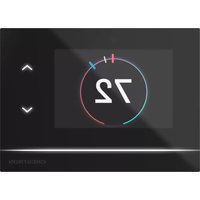
The CHV-TSTAT-FCU-PIR-10-W-Tthermostat enables precision 0-10V control of fan coil unit (FCU) HVAC systems, for variable heating, cooling, and fan speed control in hotels, apartments, or of dwelling residences. Built with versatility and energy efficiency in mind, the thermostat has the additional benefit of a built-in passive infrared (PIR) sensor to ensure that energy is never w/ vacant room. Whether used as a standalone unit or as part of a complete Crestron® control theCHV-TSTAT-FCU-PIR-10-W-Tdelivers superior functionality in a stylish wall mount design.
The backlit LCD display and large, easy-to-read push buttons make this thermostat easy to no and use. The screen displays useful information such as the current room temperature, setpoint and fan setting. Push buttons are provided for raising and lowering the temperature, putting the Heat, Cool, or Auto mode, adjusting the fan speed, and switching between temperature scales. control features include separate heating and cooling setpoints, with an optional automatic channel between heating and cooling modes. Adjustable anticipators prevent overshooting the set temperature and continuous fan operation can be selected for increased circulation.
Multiple Crestron thermostats may be networked via Cresnet ^® wired communications, a simple 4-network bus that acts as the communications backbone for Crestron lighting dimmers, keypads, thermostats, and other devices. Integrate the thermostat with a Crestron control system to end global temperature and humidity adjustments from any thermostat in the system.
Features
Key features include:
- 0-10V FCU thermostat for variable heating, cooling, and fan speed control
• Additional heating relay for traditional heating elements
• Built-in PIR sensor to detect room vacancy for energy efficiency - Cresnet® wired communications
- Backlit LCD display
- Large, easy-to-use front panel buttons for heating, cooling, fan speed, temperature scale, or temperature adjustments
• Wall-mount installation
Specifications
Product specifications for the CHV-TSTAT-FCU-PIR-10-W-T.
Product Specifications
Measurement Range
Temperature 0° to 110°F (-18° to 43°C)
Temperature Tolerance Over Full Range: ±1°F (±0.5°C)
At Room Temperatures: ±1°F (+0.1/-0.4°C)
Setpoint Range
Heat 38° to 89°F (3° to 32°C)
Cool 59° to 99°F (15° to 37°C)
Relay Rating
1A @ 40VDC or 24VAC (nominal)
Power Requirements
Cresnet 24VDC
HVAC Unit 24VAC
Power Consumption Approximately 1.5 W
Communications
Cresnet® Wired Control system integration or networking; Unit is a fully functional standalone thermostat and does not require a connection the Cresnet network
Fan Coil Unit Control
Fan Control Variable speed control via 0-10V signal;
20 mA max sink or source;
Fan speed is not full modulating. Provides four adjustable discrete voltage levels Off, Low, Medium, and High.
Cooling (Modulating Variable valve control via 0-10V signal;
Valve) 20 mA max sink or source
Heating (Modulating Variable valve control via 0-10V signal;
Valve) 20 mA max sink or source
Heating (Relay) Contact closure to HVAC
Buttons
MODE Cycles through Heat, Cool, and Auto modes
FAN Controls fan speed;
Cycles through Auto, High, Medium, Low, and Off settings
UP Raises the room's setpoint by 1^ F or 0.5^ C, depending on the active temperature scale
DOWN Lowers the room's setpoint by 1°F or 0.5°C, depending on the active temperature scale
°F/°C Switches between Fahrenheit and Celsius temperature scales
Motion Sensor
On-board passive infrared sensor;
Enables thermostat to switch between two previously defined setpoints;
When motion is detected, the Occupied setpoint is used;
When the room is vacant, the Unoccupied setpoint is used
Display
Displays current room temperature, current setpoint, current Heat or Cool mode, thermostat's call for heat cooling, and current fan setting
Type Transflective LCD, backlit
Size 2.75 in. (70 mm)
Resolution 128 x 64 pixels
Viewing Angle ±50^ horizontal at 0^ vertical;
±50° vertical at 0° horizontal
Connections
HVAC (3) 6-position terminal blocks with connections that include the following:
Power Connections (Required):
24 (C): 24VAC common terminal supplies remote 24VAC power to thermostat;
24 (R): 24VAC reference terminal - Can be connected to R by P4 jumper settir tied directly to power source
HVAC Control Connections (System Dependent):
FAN 0-10V
FAN COMMON
HEAT 0-10V
HEAT COMMON
COOL 0-10V
COOL COMMON
HEAT RELAY A
HEAT RELAY B
Network (1) 4-position terminal block;
Cresnet device port, connects to Cresnet control network
Environmental
Humidity 10% to 95% RH (noncondensing)
Construction
Plastic, surface-mountable to the front of a horizontally-oriented 1-gang electrical box
Dimensions
Height 4.00 in. (102 mm)
Width 5.00 in. (127 mm)
Depth 1.13 in. (29 mm)
Weight
5.80 oz (165 g)
Dimension Drawings

Installation
This section provides the following information:
- In the Box
• Determine the Mounting Location
• Equipment Required - Mounting
- Connect the Device
In the Box
1 CHV-TSTAT-FCU-PIR-10, 0-10 V Heating/Cooling Fan-Coil Thermostat
Additional Items
2 Screw, 6-32 x 1 in., Pan Head, Phillips (2007251)
2 Screw, M3 x 16 mm, Flat Head, Phillips (2013788)
Determine the Mounting Location
Install the thermostat away from direct sunlight, drafts, doorways, skylights, and windows. Also, sure that the thermostat is conveniently located for control access and setup.
Follow the mounting requirements below:
- Mount 60 in. (\~1.6 m) above the finished floor; this is an HVAC industry standard.
- Do not mount on an exterior wall.
Equipment Required
The following tools and hardware are required for mounting the thermostat.
• 1-gang U.S. electrical box or 1-gang U.K. electrical box (not included)
- Mounting screws (included)
• Phillips screwdriver (not included)
Mounting
Install the thermostat to an electrical box.
- Turn the HVAC system power off.
- Separate the thermostat front plate from the rear plate. It may be necessary to exert removing the front plate.
- Feed the HVAC wiring from the electrical box through the hole in the center of the re
- Make HVAC connections. For details, refer to Connect the Device on page 16.
CAUTION: To avoid a possible short circuit, ensure excess wire is inside the electrical b not pinched between the box and the device.
NOTE: To ensure accurate temperature readings, plug the wire hole with insulation to p drafts in the back of the unit.
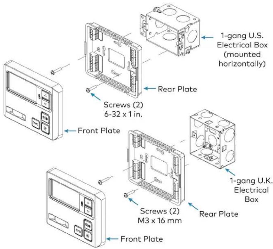
- Attach the thermostat rear plate to the electrical box using the included screws. For U.S. installations, use the 6-32 x 1 in. screws. For U.K.-style installations, use the M3 x 16 m
- Attach the front plate.
CAUTION: Do not press on the LCD display during mounting, as this may cause the s crack.
-
Carefully remove the warning label from the LCD display on the front plate.
-
Turn the HVAC system power on.
Installation in U.S. Electrical Box (top) and U.K. Square Electrical Box (bottom)
text_image
1-gang U.S. Electrical Box (mounted horizontally) Screws (2) 6-32 x 1 in. Rear Plate Front Plate Screws (2) M3 x 16 mm Rear Plate 1-gang U.K. Electrical Box Front PlateConnect the Device
Make the necessary connections as called out in the illustrations. A miniature flathead screwdrive supplied) is required to attach the control wires from the HVAC system.
Apply power after all connections have been made.
If the system being connected does not match the system described below, contact Crestron Technical Support for assistance.
Wiring Diagrams
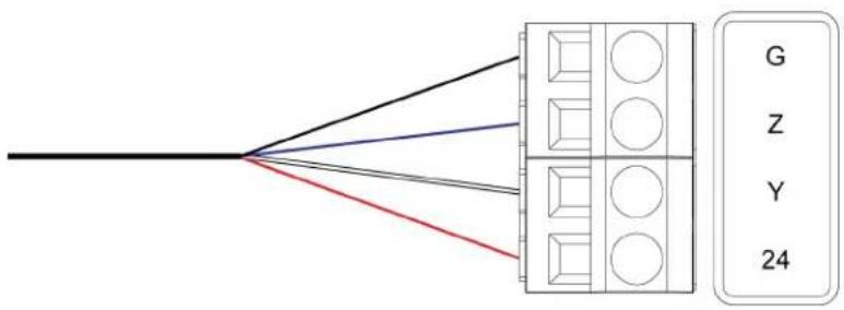
Cresnet ^® Wire Connections
flowchart
graph TD
    A["Black Line"] --> B["Grid"]
    C["Red Line"] --> B
    D["Blue Line"] --> B
    E["Gray Line"] --> B
    F["White Line"] --> B
    G["G"] --> H["Z"]
    I["Y"] --> J["Y"]
    K["24"] --> L["24"]
Jumper Connections
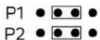
Jumper position to draw power from Cresnet. Any other jumper position draws power from HVAC system.
HVAC Connections
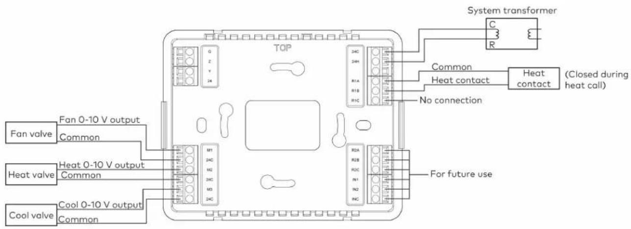
text_image
System transformer C R TOP Common Heat contact Heat contact (Closed during heat call) No connection Fan valve Fan 0-10 V output Common Heat valve Heat 0-10 V output Common Cool valve Cool 0-10 V output Common M1 24C M2 34C M3 24C R1A R1B R1C R2A R2B R2C IN1 IN2 R4C For future useNOTES:
- The thermostat does not provide power. Heat contacts require an in-line power source.
- Fan valve: The fan speed is not full modulating. It provides four adjustable discrete vol levels for Off, Low, Medium, and High.
Configuration
Before using the thermostat, ensure it is using the latest firmware. Check for the latest firm www.crestron.com/firmware. Load the firmware onto the thermostat using Crestron Toolbox™ software.
This section provides the following information:
- Setup Mode
- Configure the Thermostat
Setup Mode
This section explains how to enter, exit, and navigate Setup mode on the thermostat.
Enter Setup Mode
CHV-TSTAT-FCU-PIR-10-W-T Front Panel Buttons
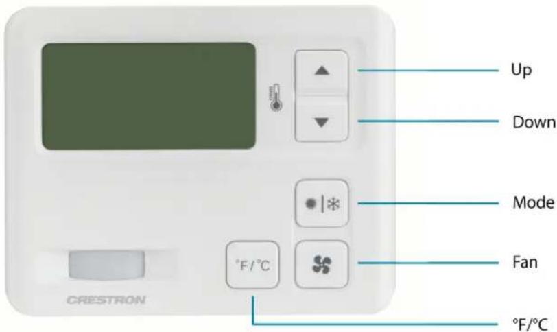
text_image
Up Down Mode Fan °F/°C CRESTRON °F/°CTo enter Setup mode, press and hold the Down button. While holding the Down button, simultaneously press and hold the Mode and Fan buttons until the SETUP: SYSTEM screen is displayed.
SETUP: SYSTEM
Heat Type: 0-10V Relay
PIR: OFF
Local Auto: DISABLED
Exit Setup Mode
To exit Setup mode, press and hold the Down button. While holding the Down button, simultaneously press and hold the Mode and Fan buttons until the home screen is displayed.
Navigate Setup Mode
When the device is in Setup mode, press the Mode button to advance to the next screen, press the Fan button to scroll vertically through the setup options on the screen, and press the Up and Down buttons to change the value for the selected item.
Configure the Thermostat
SETUP: SYSTEM Screen
SETUP: SYSTEM
Heat Type: 0-10V Relay
PIR: OFF
Local Auto: DISABLED
Use the Heat Type option to select the type of HVAC system that the thermostat is contro Use the PIR option to enable or disable the built-in passive infrared sensor.
NOTE: While PIR is disabled, the thermostat will not report room vacancy status to the control system.
Use the Local Auto option to enable or disable end user access to Auto Mode from the home screen.
SETUP: SYSTEM PERF Screen
SETUP: SYSTEM PERF
Heat Anticipator: 0
Fan Cool Down Time: 60
Use the Heat Anticipator setting to control the steady-state regulation band size. A lower setting results in more frequent cycles and faster response; a higher setting results in less frequent c slower response.
NOTE: When the 0-10V Heat Type is selected on the SETUP: SYSTEM screen, the Heat Anticipator cannot be set.
Use the Fan Cool Down Time setting to control how long the fan will run after a heating call is finished.
SETUP: DEVICE OPTS Screen
SETUP: DEVICE OPTS
Network ID: 97
LCD Contrast: 5
chv-tstat-fcu-pir-10
[v1.000.0913, #00D19753]
The Network ID must match the NET ID specified in the system program.
Use the LCD Contrast setting to change the contrast of the LCD screen.
The device name, current firmware version, and identification number are listed at the bottom screen.
BOOKED TIMEOUT Screen
BOOKED TIMEOUT
Timeout: 00:30
The BOOKED TIMEOUT setting determines how long the room must be empty before entering vacant state. Room emptiness is recorded when the PIR sensor does not detect motion. The state is defined in the control system program.
Use BOOKED TIMEOUT in a room that is occupied regularly, such as in a booked hotel room BOOKED TIMEOUT for a longer period of time than UNBOOKED TIMEOUT to ensure that the room does not enter the vacancy state while regularly occupied.
UNBOOKED TIMEOUT Screen
UNBOOKED TIMEOUT
Timeout: 00:30
The UNBOOKED TIMEOUT setting determines how long the room must be empty before entering vacant state. Room emptiness is recorded when the PIR sensor does not detect motion. The state is defined in the control system program.
Use UNBOOKED TIMEOUT in a room that is not occupied regularly, such as in a vacant hotel room. Set UNBOOKED TIMEOUT for a shorter period of time than BOOKED TIMEOUT so the room can enter the vacancy state quicker, which ensures that excess heating or cooling energy is not expended in room.
SETUP: MIN/MAX Screen
| SETUP: MIN/MAX | |||
| HEAT | COOL | AUTO | |
| Min: | 45 | 45 | 45 |
| Max: | 89 | 89 | 45 |
Set the minimum (Min) and maximum (Max) temperature setpoints for the HEAT, COOL, and AUTO modes.
SETUP: SERVICE/TEST Screen
| SETUP: SERVICE/TEST | |
| Heat Call: | 0.0V |
| Cool Call: | 0.0V |
| FAN Call: | 0.0V |
| PIR: | |
The SETUP: SERVICE/TEST screen allows device testing while bypassing all system delays. The Heat, Cool, and Fan calls are settable in 0.1V increments. When the device operates as a relay, Heat Call is relegated to ON or OFF.
PIR displays DETECTED when motion is detected by the PIR sensor.
SETUP: DISP OPTIONS Screen
| SETUP: DISP OPTIONS | |
| Temp Disp Offset: | 0 |
| Display Temp: | Y |
The SETUP: DISP OPTIONS screen allows both displayed and regulated temperature adjustment.
Use the Temp Disp Offset setting to alter the home screen's temperature output by the number of degrees selected.
Set Display Temp to Y to display the ambient and setpoint temperatures on the device's home screen. Set Display Temp to N to display only the setpoint temperature on the device's home screen.
SETUP: FAN VOLTAGE Screen
| SETUP: FAN VOLTAGE | |
| High: | 7.3V |
| Medium: | 5.1V |
| Low: | 2.9V |
Use the SETUP: FAN VOLTAGE screen to select the voltages corresponding to the high, medium low fan speeds.
Operation
To operate the CHV-TSTAT-FCU-PIR-10-W-T from the main user-facing UI, use the front panel CHV-TSTAT-FCU-PIR-10-W-T Front Panel Buttons

text_image
Up Down Mode Fan °F/°C CRESTRON °F/°C- Press the Up or Down buttons to raise or lower (respectively) the heat, cool, and auto setpoints.
- Press the Mode button to cycle through Heat, Cool, or Auto mode.
- Heat: Controls only the heating system.
Cool: Controls only the cooling system.
- Auto (if enabled): Allows the thermostat to automatically switch between the heating cooling systems.
- Press the Fan button to cycle through the Auto, High, Medium, Low, and Off fan speed
- Press the °F/°C button to switch between Fahrenheit or Celsius temperature scales.
While in Fahrenheit, the Up and Down buttons will adjust the system setpoint by 1°F per press.
While in Celsius, the Up and Down buttons will adjust the system setpoint by 0.5°C per press.
Resources
The following resources are provided for the CHV-TSTAT-FCU-PIR-10-W-T.
NOTE: You may need to provide your Crestron.com web account credentials when prompted to access some of the following resources.
Crestron Support and Training
- Crestron True Blue Support
• Crestron Resource Library
• Crestron Online Help (OLH) - Crestron Training Institute (CTI) Portal
Programmer and Developer Resources
- help.crestron.com: Provides help files for Crestron programming tools such as SIMPL, SIMPL# and Crestron Toolbox™ software
• developer.crestron.com: Provides developer documentation for Crestron APIs, SDKs, and other development tools
Product Certificates
To search for product certificates, refer to support.crestron.com/app/certificates.