
IP6112 - Security Camera Vivotek - Free user manual and instructions
Find the device manual for free IP6112 Vivotek in PDF.


| Product Type | Network Camera (IP61x2) |
| Brand | Vivotek |
| Model | IP6112 |
| Dimensions | 140 mm (L) x 70 mm (W) x 55 mm (H) |
| Weight | 430 g |
| Power Consumption | Max 7.0 W |
| Power Adapter Input | 100-240VAC, 50/60Hz, 0.4A |
| Power Adapter Output | 12VDC, 1.5A |
| Video Codec | MPEG4 Simple Profile / MJPEG (selectable) |
| Maximum Resolution | 704x480 (NTSC) / 704x576 (PAL) at 15/12 fps |
| Audio | Full-duplex, 32/24/8 Kbps, acoustic echo cancellation |
| Network Interface | 10/100BaseT Ethernet, Auto-negotiation |
| Supported Protocols | TCP/IP, HTTP, SMTP, FTP, NTP, DNS, UPnP, DDNS, DHCP |
| Motion Detection | Up to 3 configurable windows |
| Digital I/O | 1 sensor input (12VDC, 50mA), 1 relay output (24VDC 1A / 125VAC 0.5A) |
| Lens | CS mount, F2.0, f=6.0mm |
| Image Sensor | 1/3" color CCD, 0.5 Lux / F2.0 |
| Operating Temperature | 0°C to 40°C (32°F to 102°F) |
| Humidity | 85% RH (non-condensing) |
| Security | Password-protected administrator and user accounts (up to 20 users) |
| Maintenance | Clean lens with soft, dry cloth; avoid liquids |
| Spare Parts & Repairability | Contact Vivotek or authorized reseller; no user-serviceable parts inside |
| Compliance | CE, FCC Class B |
Frequently Asked Questions - IP6112 Vivotek
User questions about IP6112 Vivotek
0 question about this device. Answer the ones you know or ask your own.
Ask a new question about this device
Download the instructions for your Security Camera in PDF format for free! Find your manual IP6112 - Vivotek and take your electronic device back in hand. On this page are published all the documents necessary for the use of your device. IP6112 by Vivotek.
USER MANUAL IP6112 Vivotek
natural_image
Exterior view of a silver camera with lens and control panel (no visible text or symbols)Product name: Network Camera (IP61x2)
Release Date: 2006/04/04
Manual Revision: 1.10
Web site: www.vivotek.com
Email: technical@vivotek.com
sales@vivotek.com
Made in Taiwan. © Copyright 2000-2006. All rights reserved
Before You Use This Product
The use of surveillance devices may be prohibited in your country by law. The Network Camera is not only a high-performance web-ready camera but also can be part of a flexible surveillance system. It is the user's responsibility to ensure that the operation of such devices is legal before installing this unit for its intended use.
It is important to first verify that all contents received are complete according to the list in the "Package Contents" chapter. Take notice of the warnings in "Installation Guide" before the Network Camera is installed, then carefully read and follow the instructions in the "Installation" chapter to avoid damages due to faulty assembly and installation. This also ensures the product is used properly as intended.
The Network Camera is a network device and its use should be straightforward for those who have basic network knowledge. The “Troubleshooting” chapter in the Appendix provides remedies to the most common errors in set up and configuration. You should consult this chapter first if you run into a system error.
The Network Camera is designed for various applications including video sharing, general security/surveillance, etc. The “How to Use” chapter suggests ways to best utilize the Network Camera and ensure proper operations. For the creative and professional developers, the "URL Commands of the Network Camera" chapter serves to be a helpful reference to customize existing homepages or integrating with the current web server.
For paragraphs preceded by ⚠ the reader should use caution to understand completely the warnings. Ignoring the warnings may result in serious hazards or injuries.
Package Contents
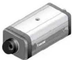
IP61×2
natural_image
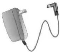
Exterior view of a metallic cylindrical device with a central hub and mounting holes (no visible text or symbols)Power adapter
natural_image
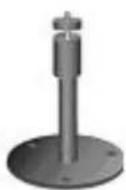
Illustration of a connected power adapter with a cable (no text or symbols visible)Camera stand
Wrench
Software CD

Quick installation guide

Warranty card
Table of Contents
Before You Use This Product....2
Package Contents .... 3
Table of Contents....1
Installation 4
Hardware Installation 4
To install in Ethernet....5
Software Installation 6
Initial Access to the Network Camera.... 10
Installing Plug-in 10
Check Network Settings 11
Add Password to Prevent Unauthorized Access.... 11
How to Use ....12
Authentication....12
Primary User's Capabilities 13
Main Screen with Camera View 13
The Configuration: 14
The camera view.... 14
Client Settings 15
Administrator's Capabilities 17
Fine-tuning for Best Performance.... 17
For Best Real-time Video Images.... 18
Only Quality Images Will Do 18
Somewhere Between Real-time and Clear Images 19
Select for Motion JPEG....19
Opening Accounts for New Users 20
Protect Network Camera by Passwords....20
More Flexible Options for Viewers 21
Build a Multimedia Web Attraction Site.... 21
Demo on Multiple Sites – Mid-scale Service.... 21
Product Demo for E-business – Large-scale Service 21
If the web space has FTP service.... 22
If the web space has no FTP service 23
Build a Security Application.... 25
Send Snapshots When Motion is Detected 26
Definitions in Configuration 28
System Parameters 30
User Group Administration 31
Edit User 33
Network Settings 34
General....34
HTTP 35
Streaming 35
DDNS & UPnP 37
Mail & FTP 39
SMTP 39
FTP 39
Video Codec Parameters 42
Image Settings 44
CCD Settings 45
Audio 46
Motion Detection 48
Application Setup 50
Weekly Schedule 50
Event Operation 50
Sequential Operation 51
Naming rule of snapshot file.... 52
Viewing System Log 54
Viewing System Parameters 54
Factory Default 54
Appendix 55
A. Troubleshooting 55
C. URL commands of Network Camera 59
Overview 59
Style convention....59
General CGI URL syntax and parameters 60
Get server parameter values 60
Set server parameter values 62
Available parameters on the server 63
Application page CGI command 74
Drive the digital output 77
Query status of the digital input 78
Query status of the digital output....79
Capture single snapshot 80
Account management 80
System logs....82
Configuration file 82
System Information 83
D. Technical Specifications.... 85
Electromagnetic Compatibility (EMC) 6
Installation
Hardware Installation
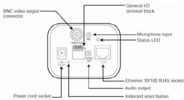
Please verify that your product package contains all the accessories listed in the foregoing Package Contents. Depending on the user's application, an Ethernet cable may be needed. The Ethernet cable should meet the specs of UTP Category 5 and not exceed 100 meters in length.
Connect the power adapter jack to the Network Camera before plugging in to the power socket. This will reduce the risk of accidental electric shock.
Upon powering up, the device runs through a self-test procedure and the front LEDs will blink between green and red for a few times. If self-test passes, the LEDs will shut off and the Network Camera will be on stand-by and ready for software installation. If self-test fails the red LED will blink several times. Refer to Appendix A for troubleshooting.
The Network Camera will first detect Ethernet. If it does not connect to Ethernet, the Network Camera will try WLAN. During the searching and connecting process to the wireless access point or station, the LED of the Network Camera will keep red. Until the Network Camera is connected to the other wireless device, the LED will become green and flash. Operating in either network mode, the green LED will flash every second as heartbeat to indicate alive.
To install in Ethernet
Make sure the Ethernet is firmly connected to a switch hub. After attaching the Ethernet cable plug in the power adapter. If the LED turns out to be steady green after self-test, go to next paragraph "Software Installation". If the Ethernet is not available, the Network Camera will switch to wireless LAN mode.
The Network Camera provides a general I/O terminal block with one digital input and one relay switch for device control. Pin 3 and Pin 4 can be connected to an external sensor device and the state of voltage can be monitored from the initial state 'LOW'. The relay switches Pin 1 and Pin 2 can be used to turn on or off an external device.

Consult with the dealer of the peripherals for correct installation.
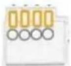
1234
1 SW_COMMON OUTPUT (open from SW_OPEN at initial state) (close with SW_OPEN when set DO to ON)
2 SW_NOPEN OUTPUT (Max. 1A, 24VDC or 0.5A, 125VAC)
3 DI+ INPUT (Max. 50mA, 12VDC)
4 DI- INPUT (Initial state of DI is low)
The Network Camera also provides the auto iris lens connector. If the auto iris lens is used, AES option in CCD settings must be turned OFF. And you also have to select VIDEO drive or DC drive lens by select correct iris mode in CCD settings. The pin assignment of the auto iris lens connector is as follows.
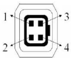
Video Drive DC Drive
- Ground, Shield 1. Driver -
- Not used 2. Driver +
- Video signal 3. Damp +
- Power source 4. Damp -
Software Installation
In this manual, "User" refers to whoever has access to the Network Camera, and "Administrator" refers to the person who can configure the Network Camera and grant user access to the camera.
At the end of the hardware installation, the Administrator must place the product software CD into the CD-ROM drive of the PC running in MS Windows. An auto-run program will pop up (If the program is not on auto-run, go to the root directory of the software CD and click on "autorun.exe").
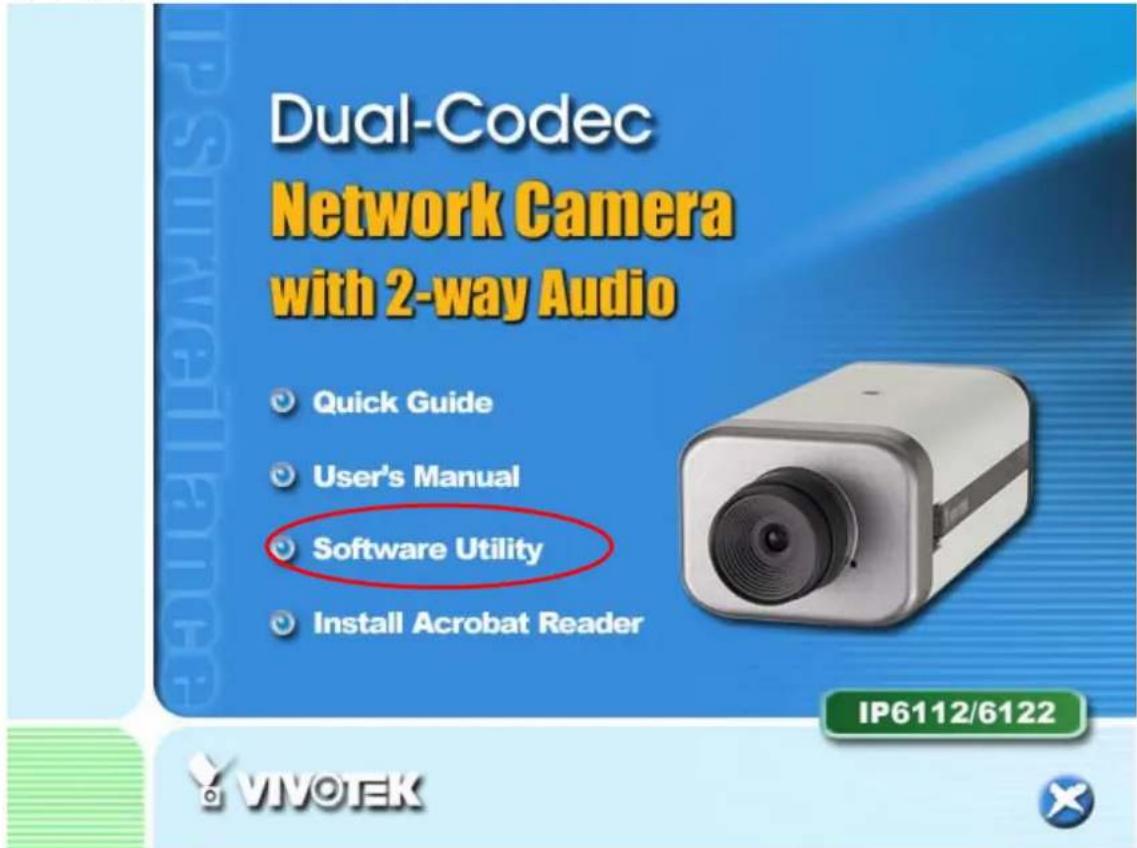
Click on “Software Utility” item, after the window contains changed, click on “Installation Wizard” to run Vivotek’s installation program.
16-CH Smart VS-IP Recorder
Installation Wizard

User's Manual
Install Software DVR

Quick Guide

User's Manual

Release Note
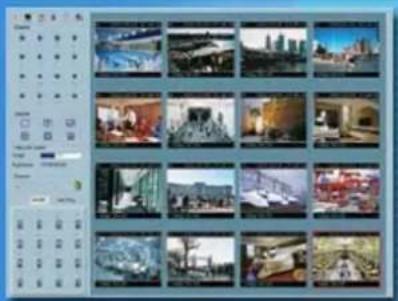
natural_image
Grid of 20 grayscale photos showing urban and rural landscapes, no visible text or symbolsST3402

VIVOEK

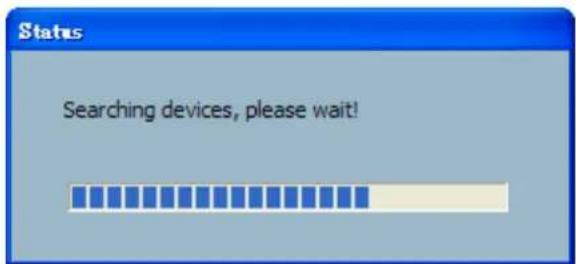
Upon Installation Wizard's start up, a searching box will pop up. This program searches for Vivotek's product on the same LAN:
After searching, Vivotek Video Servers or Network Cameras will be located by the Installation Wizard. There may be several entries shown in the window. The Administrator may differentiate the Network Cameras with the serial number.
For the series number in the "Serial Number" field, please check the label on the bottom of the camera.
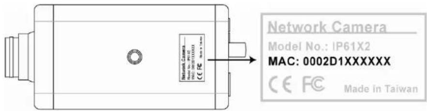
This serial number is the same as Ethernet address, for example: 0002D1140000=00-02-D1-14-00-00
The IP addresses shown in the "Current IP Address" field reflect those on the local network. They may be from the DHCP server. If there is no DHCP server, the camera will try to find a free IP address (this takes from 15 second to 3 minutes, depending on the LAN status). The method of finding IP address is seeking from 192.168.0.99, to 192.168.0.254. If any of the address inside this range is free, the Network Camera will be assigned to this IP address, and its subnet mask would be 255.255.255.0. If none of the addresses is free, the Network Camera will try the range from 192.168.0.2 to 192.168.0.98. After an IP address is assigned to the camera, the "Activity" status LED blinks.
The Vivotek's new UPnP function will always assign an IP address for the Network Camera. The Administrator can click on button "Link to selected device" to connect the I.E. to the camera.
If the camera is not on the IP installer list, click on the "Search" button to search for the camera on the LAN.
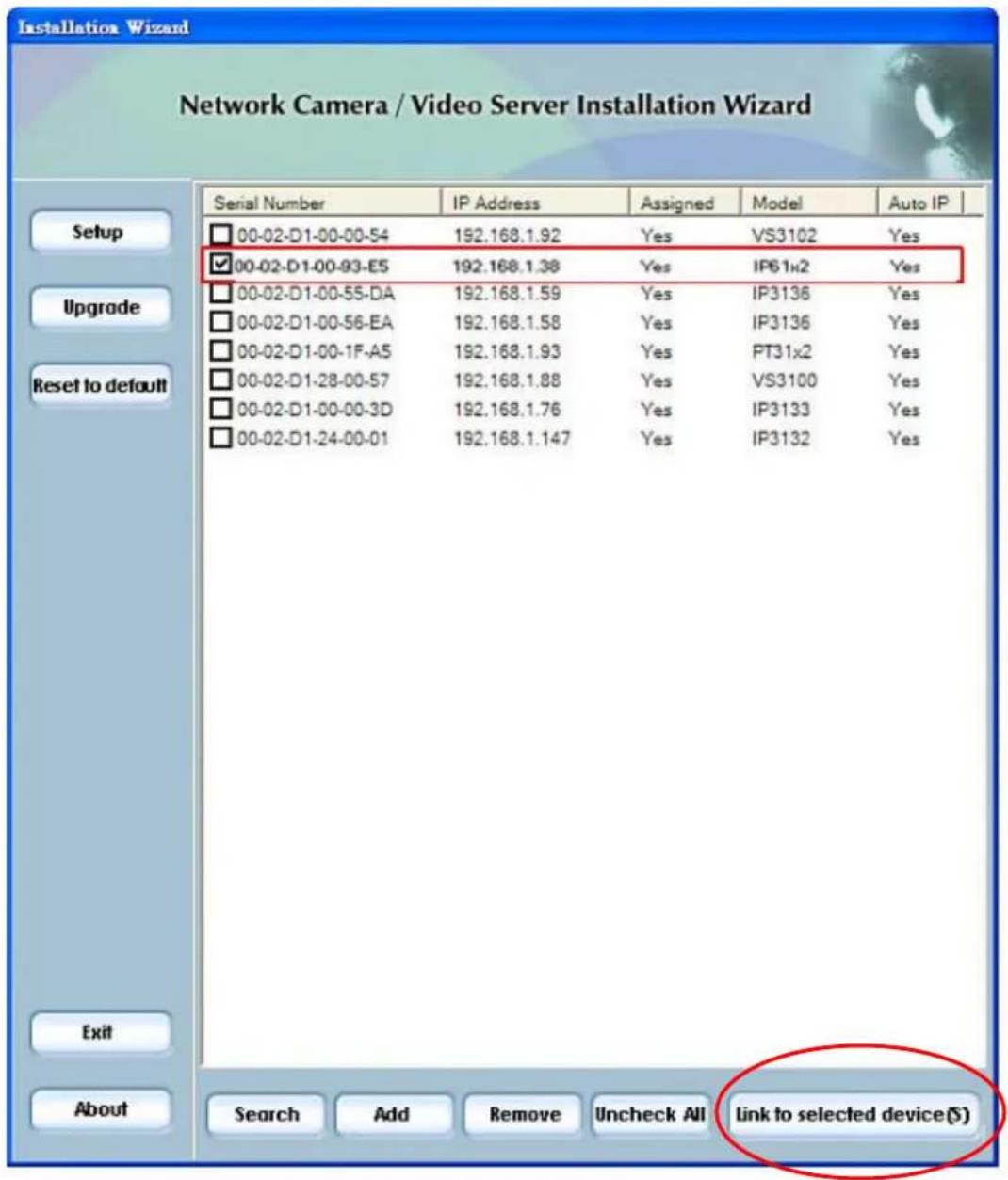
For more detailed usage of the Installation Wizard, please refer to the user's manual of the Installation Wizard.
Initial Access to the Network Camera
Installing Plug-in
For the initial access to the Network Camera in Windows, the web browser may prompt for permission to install a new plug-in for the Network Camera after a period of time of downloading. Permission request depends on the Internet security settings of the user's PC or notebook. If the highest security level is set, the computer may prohibit any installation and execution attempt. This plug-in has been registered for certificate and is used to display the video in the browser. Users may click on to proceed. If the web browser does not allow the user to continue to install, check the Internet security option and lower the security levels or contact your IT or networking supervisor for help.
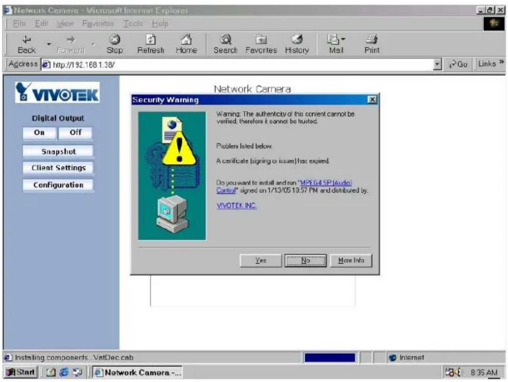
Check Network Settings
The Network Camera can be connected either before or immediately after software installation onto the Local Area Network. The Administrator should complete the network settings on the configuration page, including the correct subnet mask and IP address of gateway and DNS. Ask your network administrator or Internet service provider for the detail information. By default the Network Camera requires the Administrator to run installation every time it reboots. If the network settings are to remain unchanged, disable the Install option. Refer to “Network settings” on the System Configuration page for details. If any setting is entered incorrectly and cannot proceed to setting up the Network Camera, restore the factory settings following the steps in the “Troubleshooting” chapter of the Appendix.
Add Password to Prevent Unauthorized Access
The default Administrator's password is blank and the Network Camera initially will not ask for any password. The Administrator should immediately implement a new password as a matter of prudent security practice. Once the Administrator's password is saved, the Network Camera will ask for the user's name and password before each access. The Administrator can set up a maximum of twenty (20) user accounts. Each user can access the Network Camera except to perform system configuration. Some critical functions are exclusive for the Administrator, such as system configuration, user administration, and software upgrades. The user name for the Administrator is permanently assigned as "root". Once the password is changed, the browser will display an authentication window to ask for the new password. Once the password is set, there is no provision to recover the Administrator's password. The only option is to restore to the original factory default settings.
How to Use
Authentication
After opening the web browser and typing in the URL of the Network Camera, a dialogue window pops up to request a username and password.
The foreground is the login window and the background shows the message if authentication fails. The user may check the option box to save the password for future convenience.
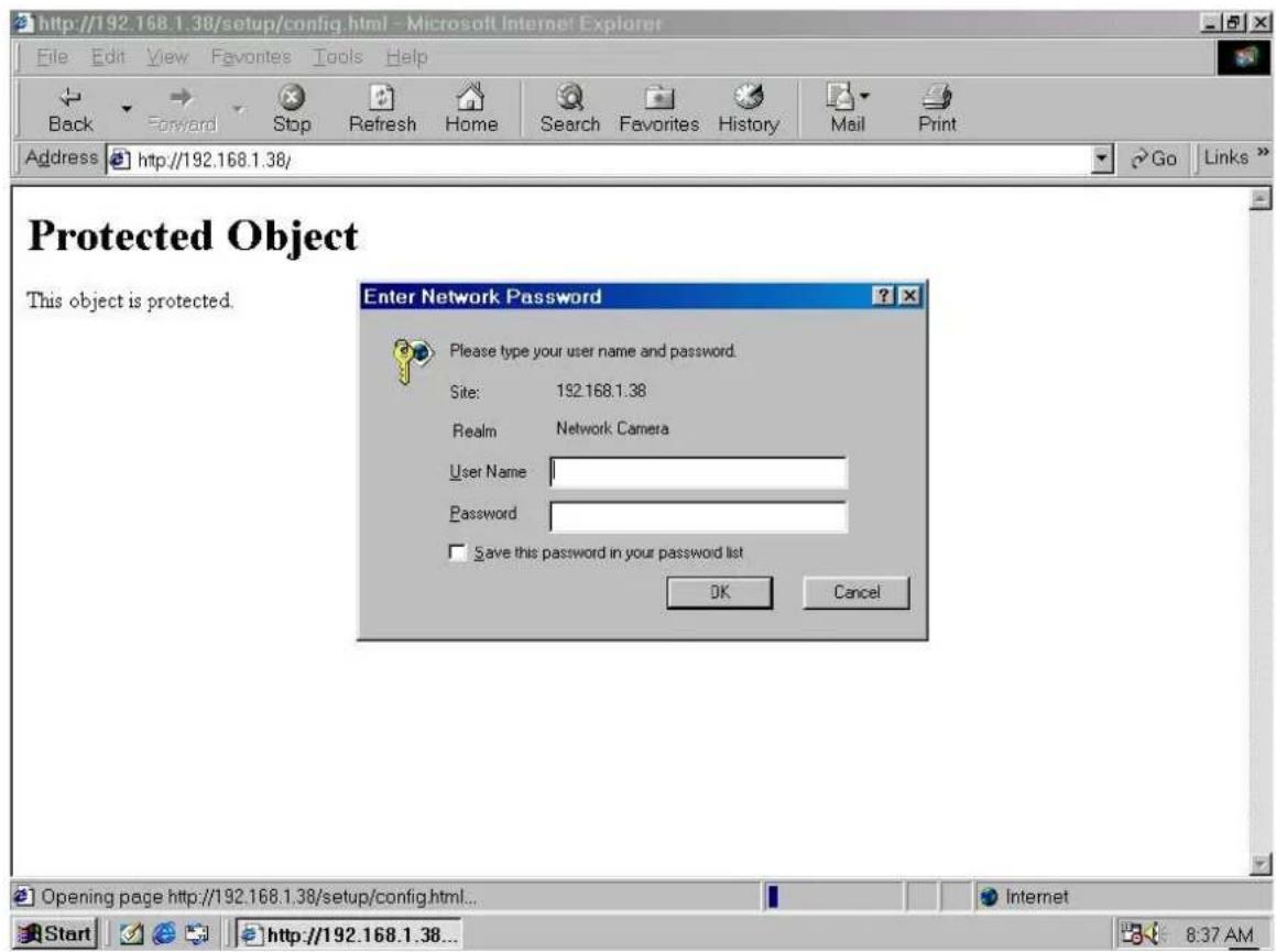
Primary User's Capabilities
Main Screen with Camera View
The main page layout has two parts:
Configuration functions: The camera can be configured using these user interfaces.
Camera View: What the camera sees.
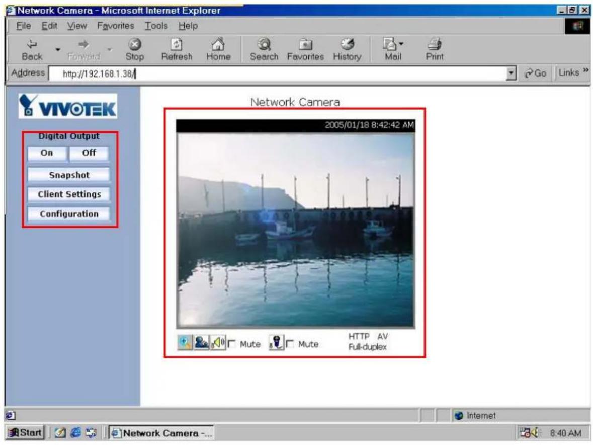
The Configuration:
"Digital Output"
Clicking on the "On" or "Off" button turns the digital output to either on or off status.
"Snapshot"
Clicking on the "Snapshot" can get a JPEG format image of the current camera view in another window.
"Client Settings"
Clicking on this button links you to the client setting page, please check the following session for more details.
"Configuration" Only the Administrator can access camera configurations.
The camera view
The information bar at the top of the camera view shows the assigned caption and the current date/time. The information bar at the bottom of the camera view shows the current streaming mode and audio transmission mode. You can push/toggle the talk button to talk to the remote server. The volume of speaker and microphone can also be adjusted.

flowchart
graph TD
    A["Digital zoom"] --> B["Talk button"]
    B --> C["Speaker volume"]
    C --> D["Microphone volume"]
    E["UDP AV Full-duplex"] --> F["Mute"]
    F --> G["Speaker volume"]
    G --> H["Microphone volume"]
Client Settings
There are four settings for the client side.
Media Options - For the User to determine whether to receive video, audio or both.
Protocol Options – Which allows choosing on connection protocol between client and server. There are two protocol choices to optimize your usage – UDP and HTTP. The UDP protocol allows for more real-time audio and video streams. However, some packets may be lost due to network burst traffic and images may be obscured.
The HTTP protocol must be selected if the network is protected by a firewall which allows only HTTP Port (80) to be opened. If there is no restriction, UDP protocol is recommended. Generally speaking, the client's choice will be in the order of UDP → HTTP. After the Network Camera is connected successfully, "Protocol Options" will indicate the selected protocol. The selected protocol will be recorded in the user's PC and will be used for the next connection. If the network environment is changed, or the user wants to let the web browser to detect again, manually select the UDP protocol and save, then return to HOME to connect to the Network Camera.
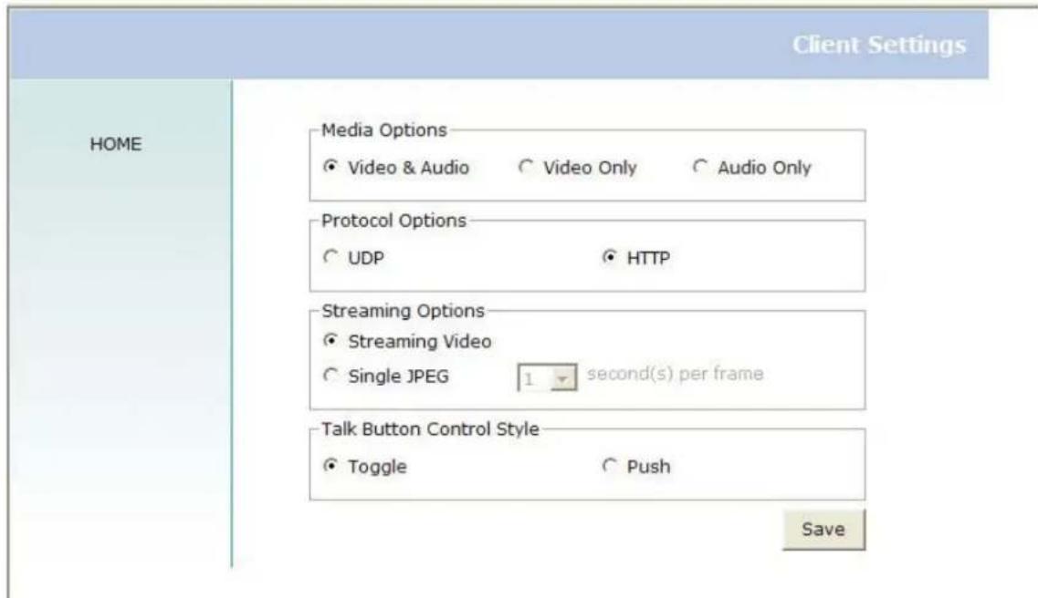
Streaming Options – For users to select the video streaming types. Select "Streaming Video" options, the video connection will keep alive to enable you to see smooth video, while "Single JPEG" options will let you see the video in JPEG format by client periodic update the JPEG image from server according to the "Frame rate" settings.
Talk Button Control Style – For the User to determine whether to “click once and talk” or “push to talk”.
Administrator's Capabilities
Fine-tuning for Best Performance
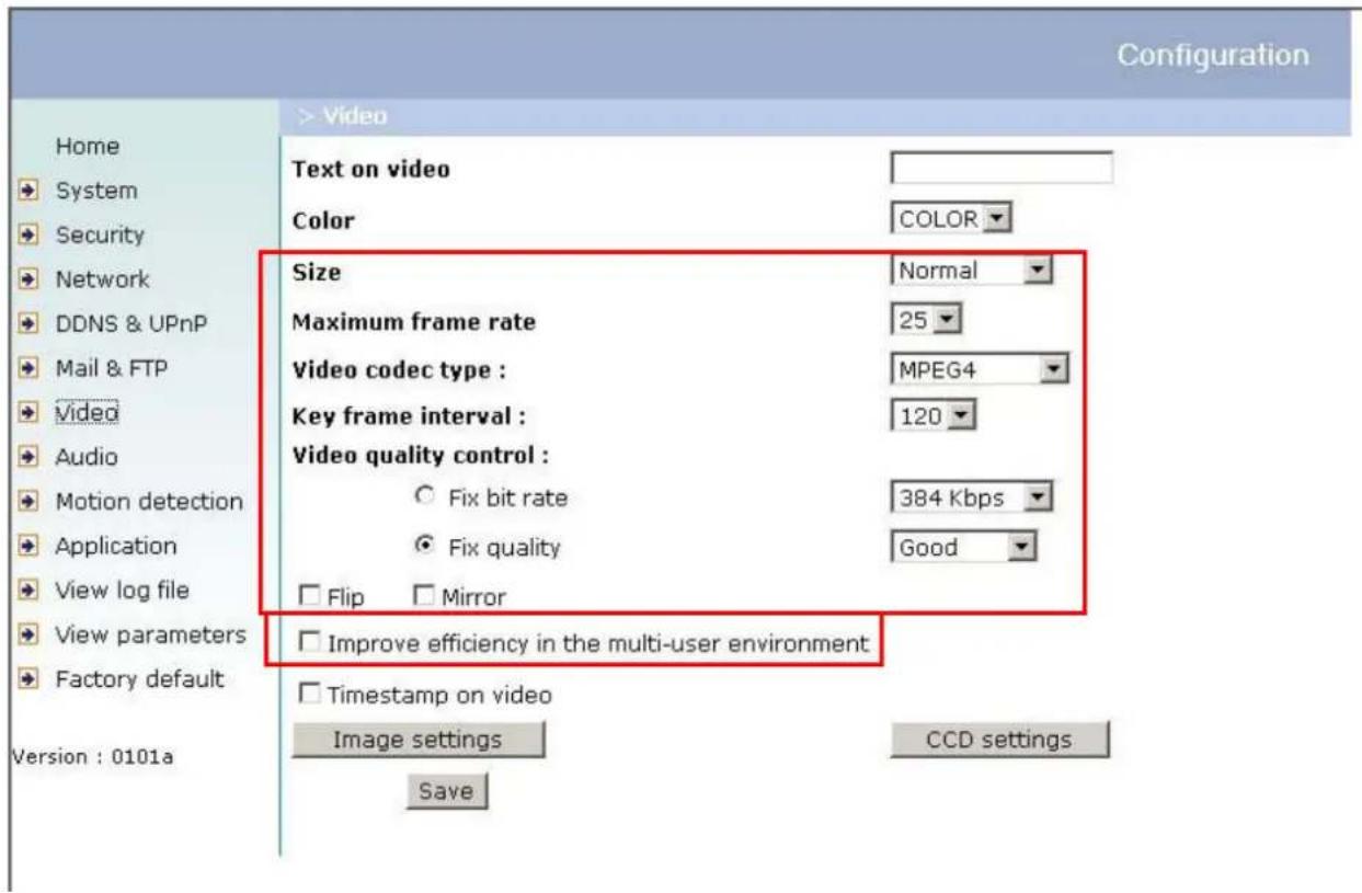
There are a few choices the Administrator is allowed to maximize the capabilities of the Network Camera. Best performance generally equates to the fastest image refresh rate with the best video quality, and at the lowest network bandwidth as possible. The six factors, "Size", "Maximum frame rate", "Video codec type", "Key frame interval", "Fix bit rate", and "Fix quality" on the Video Configuration page, are correlative to allow for achieving the best performance possible.
For Best Real-time Video Images
To achieve good real-time visual effect, the network bandwidth should be large enough to allow a transmission rate of greater than 20 image frames per second. If the broadband network is over 1 Mbps, set the “Fix bit rate” to 1000Kbps or 1200Kbps, or set “Fix quality” at the highest quality. The maximum frame rate is 25 fps in a 50Hz system and 30 fps in a 60Hz system. If your network bandwidth is more than 384Kbps, you can fix the bit rate according to your bandwidth and set the maximum frame rate to 25 fps or 30 fps. If you are shooting fast-moving images, you may want to slow the maximum frame rate down to 20 fps in order to lower the rate of data transmission. This allows for better video quality and the human eyes cannot readily detect the differences between those of 20, 25, or 30 frames per second. If your network bandwidth is below 384 Kbps, set the “Fix bit rate” according to your bandwidth and try to get the best performance by fine-tuning with the “Maximum frame rate”. In a slow network, greater frame rate results in blur images. Another work-around is to choose “Half” in the “Size” option for better images, or “Halfx2” for a larger image view. Video quality performance will vary somewhat due to the number of users viewing on the network; even when the parameters have initially been finely tuned. Performance will also suffer due to poor connectivity because of the network’s burst constraint.
In multi-user environment, the user who has poor network performance will receive only the key frame in MPEG4 format. Try to reduce the key frame interval can improve the frame rate for poor network performance, but the penalty is the increasing of network traffic. If the server is running on the Internet, select the “improve efficiency in the multi-user environment” will improve the efficiency in the multi-user environment.
Only Quality Images Will Do
To have the best video quality, you should set "Fix quality" at "Detailed" or "Excellent" and adjust the "Maximum frame rate" to match your network's bandwidth. If your network is slow and you receive "broken" pictures, go to the HTTP protocol in "Connection type" and choose a more appropriate mode of transmission. The images may suffer a time delay due to a slower connection.
Somewhere Between Real-time and Clear Images
If you have a broadband network, set "Fix quality" at "Normal" or better, rather than setting "Fix bit rate". You can also fix the bandwidth according to your actual network speed and adjust the frame rate. Start from 30 fps down for best results but not below 15 fps. If the image qualities are not improved, select a lower bandwidth setting.
Select for Motion JPEG
The Network Camera is a camera with dual video codec, they're MPEG4 and MJPEG. If MJPEG is selected, the camera will transmit video data in JPEG format. Therefore, it requires higher bandwidth to view smooth video. General speaking, each normal sized JPEG image would be 3k\~12k bytes, depending on the selected video quality and contents. Together with the frame rate selected, the administrator can control the bandwidth of each connection.
Opening Accounts for New Users
Protect Network Camera by Passwords
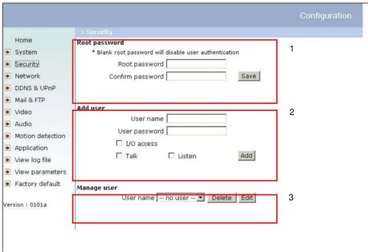
The Network Camera is shipped without any password by default. That means everyone can access the Network Camera including the configuration as long as the IP address is known. It is necessary to assign a password if the Network Camera is intended to be accessed by others. Type a new word twice in the first field to enable protection. This password is used to identify the administrator. Then add an account with user name and password for your friends in the second field. The Network Camera can provide twenty accounts for your valuable customers or friends. Each account identifies the access right rather than the real visitor. That allows multiple visitors share the same account of different level. Each account has four kinds of privileges, which can be set individually. The "I / O access" privilege permits the user
to access DI/DO of the server. The “Talk” privilege permits the user to send speech to the Network Camera. The “Listen” privilege permits the user to listen sounds from the server. You may edit or delete some users from the third field.
More Flexible Options for Viewers
If you want to have a guest account for viewers only, you just need to add a user without password and disable all the privileges. Share the account to your friends to access your camera.
Build a Multimedia Web Attraction Site
Demo on Multiple Sites - Mid-scale Service
The Network Camera can allow ten visitors on-line simultaneously. After Installation, focus the Network Camera on any object you wish to share, and tell the visitors to type in the web browser address. Caution: You may want to maintain your visitor's list in the security configuration page to block out unexpected visitors.
Product Demo for E-business - Large-scale Service
If the number of visitors has exceeded the limit, the Network Camera can allow the "overload" viewers to see the snapshots in JPEG mode, on the homepage. These are still images and will be refreshed periodically and automatically.

- Click on "Client Settings" on the homepage,
- Select "Single JPEG" in "Streaming Options",
- Set the snapshot interval to refresh the still image automatically. The longer the snapshot interval, the better the snapshot mode works for multiple viewers.
If you want to expand to allow in more viewers, the host server should be able to handle large network traffic, which must handle the picture refreshing from the Network Camera.
If the web space has FTP service
Set the Network Camera up as an FTP client to upload the pictures. The access to the Network Camera will be independent of the number of viewers and the picture quality will remain constant.
![Configuration Home System Security Network DDNS & UPnP Mail & FTP Video Audio Motion detection Application View log file View parameters Factory default Version : 0101a > Application Weekly schedule Sun Mon Tue Wed Thu Fri Sat snapshots begin at 00:00:00 [hh:mm:ss] snapshots stop at 00:00:00 [hh:mm:ss] All the time except for the above schedule Snapshot file name prefix video Event operation General Delay 3 second(s) before detecting the next event Send 1 pre-event image(s) when event occurs Trigger condition Input is high Input is low Input is rising Input is falling Detect motion in : Note: Motion detection must be setup first Trigger action Trigger output alarm while input condition matched Trigger output alarm while motion detected Upload snapshots while input condition matched Upload snapshots while motion detected Reset output Sequential operation Snapshot interval: 1 Second(s) Send snapshots by email Send snapshots by FTP FTP put snapshots with date and time suffix Save](/content/2026/06/1146004/images/5c9ffd007a51daaf698a64f1a80aca005486c530e290174043cee33164ac45f5.jpg)
- Click on "Configuration" on the homepage,
- Click on "Mail & FTP" in the left column,
- Fill in the FTP related settings including server, server port, user name and password, as well as the upload path if it is specified by the web space,
- Click on "Save",
- Click on "Application" in the left column,
- Select the day or days of the week in "Weekly schedule" you want to upload the pictures,
- Select "Sequential operation" and set the interval,
- Unselect "FTP put snapshots with date and time suffix" as the upload method and click on "Save",
- The image file uploaded to the web space is named "video.jpg". Check if the file is successfully uploaded to the correct folder,
- Prepare a homepage with the embedded image reference to the image file uploaded via FTP in advance.
If the web space has no FTP service
An auto-refresh homepage can be used to periodically poll the newest image from the Network Camera. It is most efficient if using a free web space provider as the FTP service may be limiting.
- Prepare an auto-refresh homepage as the following example. The URL of image is http://“IP address of the Network Camera”/cgi-bin/video.jpg. Modify the IP address according to your Network Camera. Define the refresh interval according to your network bandwidth for best result. If the refresh rate is too fast and there is a large number of visitors, this may overload the Network Camera and slows the response.
Example of an auto-refresh web page:
<html>
<head>
<title>Example - auto refresh</title>
</head>
<body>
<p align=left>
    <font size="7" face="Comic Sans MS" color="#FF0000">
    MiniAVServer Demo
    </font>
</p>
<p align=left>
<!-- Begin of scripts to auto refresh the image. Change the IP address in the image URL and refreshrate if necessary. //-->
<script language=javascript>
var image="http://192.168.0.203/cgi-bin/video.jpg";    //IMAGE URL
var refreshrate=5;    // SECONDS BETWEEN REFRESH
var imgwidth=352;    // IMAGE WIDTH
var imgheight=240;    // IMAGE HEIGHT
function refresh(){
document.images["pic"].src=image+"?"+new Date();
setTimeout('refresh()", refreshrate*1000);}
document.write('<img src=""+image+" " height=""+imgheight+" " width="+imgwidth+" " name="pic">');
if(document.images)window.onload=refresh;
</script>
<!-- End of scripts to auto refresh the image. //-->
</p>
</body>
</html>
Build a Security Application
The Administrator can combine options on the application page to perform many useful security applications. There are two trigger sources coming from attached devices, such as for motion detection. There are also two kinds of actions responding to such events, including uploading snapshots over the Internet and driving other attached devices. To upload the snapshots, the
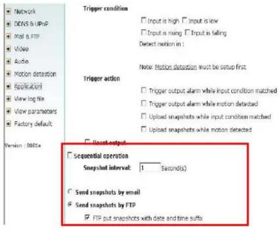
User can choose either email or FTP according to user's needs. Both e-mail and FTP use the network settings on the Mail & FTP page. Refer to the definition section for detail configuration.
-
Click on "Configuration" on the homepage,
-
Click on "Application" in the left column,
-
Check the weekdays as you need and give the period of "Snapshots begin" time and "Snapshots end" time to monitor the triggering conditions every day,
-
Check the "Event operation". The triggering condition can be set to detected motion or status of the attached
-
Set the delay before detecting next event to avoid continuous false alarms following the original event,
![Weekly schedule □ Sun □ Mon □ Tue □ Wed □ Thu □ Fri □ sat snapshots begin at [00:00:00] [hh:mm:ss] snapshots stop at [00:00:00] [hh:mm:ss] ✓ All the time except for the above schedule Snapshot file name prefix video □ Event operation General Trigger condition Delay 5 second(s) before detecting the next event Send 1 pre-event image(s) when event occurs □ Input is high □ Input is low □ Input is rising □ Input is falling Detect motion in: Trigger action Note: Motion detection must be setup first □ Trigger output alarm while input condition matched □ Trigger output alarm while motion detected □ Upload snapshots while input condition matched □ Upload snapshots while motion detected device](/content/2026/06/1146004/images/2be3871bdacf63c344aa099e972c4404fa467489a99a6cadb985effe053ea314.jpg)
Send Snapshots When Motion is Detected
If no external sensor is available, the Administrator can use the built-in motion detection to monitor any movement and send snapshots via emails for security check.
- Click on "Motion detection" in the left column,
- Check "Enable motion detection",
- Click on "New" to have a new window to monitor video,
- Type in a name to identify the new window,
- Use the mouse to click, hold, and drag the window corner to resize or the title bar to move,
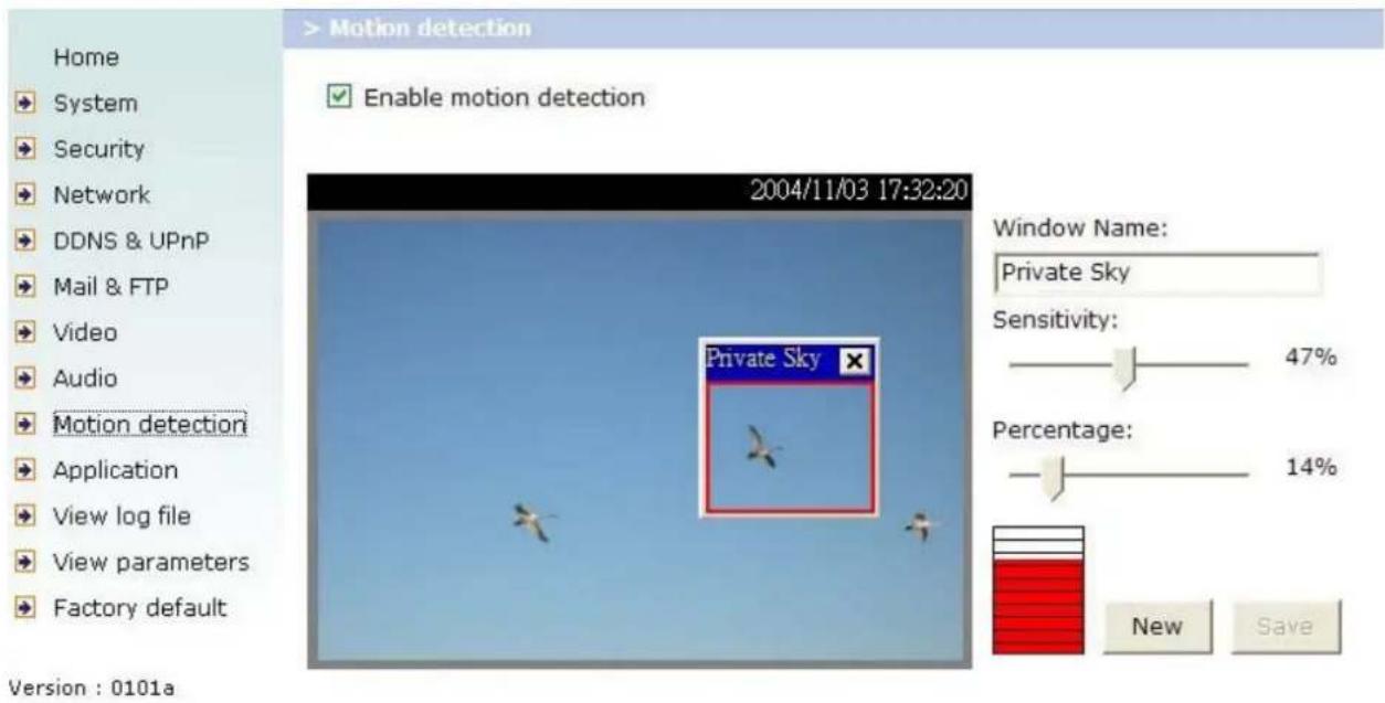
- Fine-tune using the "Sensitivity" and "Percentage" fields to best suit the camera's environment. Higher "Sensitivity" detects the slighter motion. Higher "Percentage" discriminates smaller objects,
- Clicking on "Save" enables the activity display. Green means the motion in the window is under the watermark set by the Administrator and red means it is over the watermark,
- Click on "Application" in the left column,
-
Check on the window name set in step 9,
-
Check "Upload snapshots while motion detected", if e-mailing the snapshots is preferred,
- Check "Send snapshots by email",
- Click on "Save" to validate.
Definitions in Configuration
Only the Administrator can access system configuration. Each category in the left column will be explained in the following pages. The bold texts are the specific phrases on the Option pages. The Administrator may type the URL below the figure to directly enter the frame page of configuration. If the Administrator also wants to set certain options through the URL, read the reference appendix for details.
![Configuration Home System Security Network DDNS & UPnP Mail & FTP Video Audio Motion detection Application View log file View parameters Factory default Version : 0102c > System Host name : Network Camera Turn off the LED indicator Automatically restore DO state after 1 second(s) Keep current date and time Sync with computer time PC date: 2006/04/04 [yyyy/mm/dd] PC time: 16:06:22 [hh:mm:ss] Manual Date: 2006/04/04 [yyyy/mm/dd] Time: 16:05:13 [hh:mm:ss] Automatic NTP server: skip to invoke default server Time zone: GMT+8:00 Update interval: One hour Save](/content/2026/06/1146004/images/ba9d82bf3bcfd332af1b69c749b6f6c973189a49a9d493023628748a67aa94de.jpg)
<url> http://<Network Camera>/setup/config.html
<Network Camera> is the domain name or original IP address of the Network Camera.
<url> http://<Network Camera>/setup/system.vspx
System Parameters
"Host name" The text displays the title at the top of the main page.
"Turn off the LED indicator" Check this option to shut off the LED on the rear. It can prevent the camera's operation being noticed.
"Keep current date and time" Click on this to reserve the current date and time of the Network Camera. An internal real-time clock maintains the date and time even when the power of the system is turned off.
"Sync with computer time" Synchronize the date and time of the Network Camera with the local computer. The read-only date and time of PC is displayed as updated.
"Manual" Adjust the date and time according to what is entered by the Administrator. Notice the format in the related fields while doing the entry.
"Automatic" Synchronize with the NTP server over the Internet whenever the Network Camera starts up. It will fail if the assigned time-server cannot be reached.
“NTP server” Assign the IP address or domain name of the time-server. Leaving the text box blank connects the Network Camera to the default time-servers.
"Time zone" Adjust the time with that of the time-servers for local settings.
"Update interval" Select hourly, daily, weekly, or monthly update with the time on the NTP server.
Remember to click on Save to immediately validate the changes. Otherwise, the correct time will not be synchronized.
User Group Administration
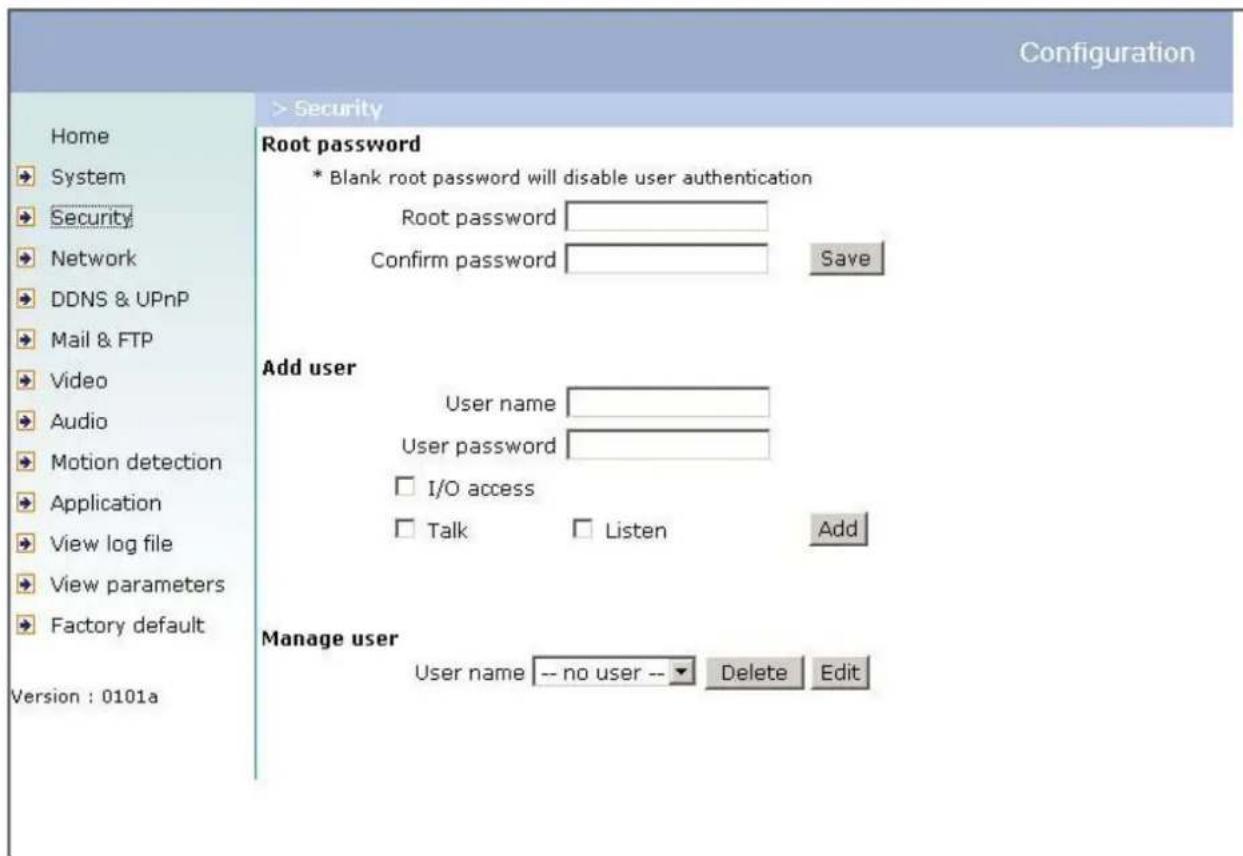
"Root password" Change the Administrator's password by typing in the new password identically in both text boxes. The typed entries will be displayed as asterisks for security purposes. After pressing Save, the web browser will ask the Administrator for the new password for access.
“Add user” Type the new user's name and password and press Add to insert the new entry. The new user will be displayed in the user name list. There is a maximum of twenty user accounts. Each user can have four privileges – “I / O access”, “Talk” and “Listen”.
"I / O access" Allows user to control the DO and get status of the DI.
"Talk" Allows user to talk to the server.
"Listen" Allows user to listen from the server.
"Delete user" Pull down the user list to find the user's name and press delete to complete.
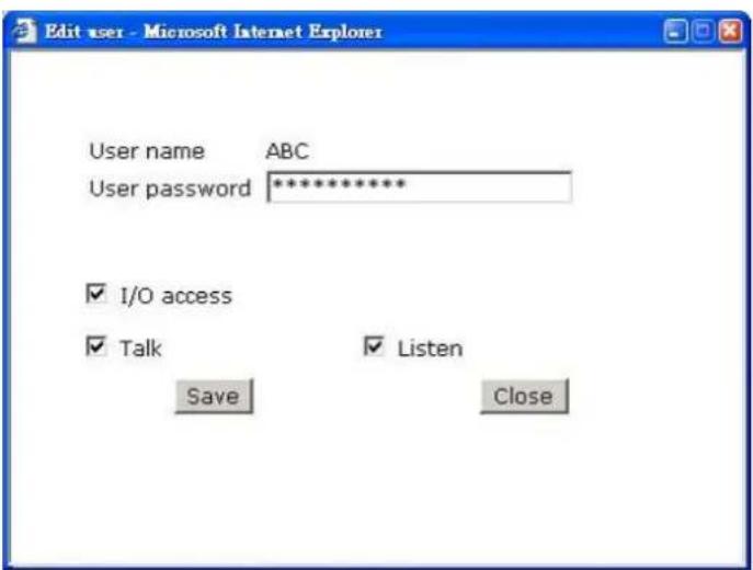
“Edit user” Pull down the user list to find the user's name and press edit to edit the user's password and privilege.
Edit User
Type the new password, change the privilege and press to modify the account.
Network Settings
Any changes made on this page will need to restart the system in order to validate the changes. Make sure every field is entered correctly before clicking on Save.
"Get IP address automatically" & "Use fixed IP address"
The default status is “Get IP address automatically”. This can be tedious having to perform software installation whenever the Network Camera starts. Therefore, once the network settings, especially the IP address, have been entered correctly, select “Use fixed IP address” then the Network Camera will skip installation at the next boot. The Network Camera can automatically restart and operate normally after a power outage. Users can run IP installer to check the IP address assigned to the Network Camera if the IP address is forgotten or using the UPnP function provided by the Network Camera (MS Windows XP provides UPnP function at My Network Place). As for how to get IP address automatically, please refer to the section of Software Installation.
General
"I P address" This is necessary for network identification.
"Subnet mask" It is used to determine if the destination is in the same subnet. The default value is "255.255.255.0".
“Default router” This is the gateway used to forward frames to destinations in different subnet. Invalid router setting will fail the transmission to destinations in different subnet.
"Primary DNS" The primary domain name server that translates hostnames into IP addresses.
"Secondary DNS" The secondary domain name server that backups the Primary DNS.
HTTP
“HTTP port” This can be other than the default Port 80. Once the port is changed, the User must be notified the change for the connection to be successful. For instance, when the Administrator changes the HTTP port of the Network Camera whose IP address is 192.168.0.100 from 80 to 8080, the User must type in the web browser “http://192.168.0.100:8080” instead of “http://192.168.0.100”.
Streaming
"UDP audio channel port" This can be something other than the default port 5002 in order to work with the port opened by the firewall.
"UDP video channel port" This can be something other than the default port 5003 in order to work with the port opened by the firewall.
Configuration
Home
System
→ Security
→ Network
DDNS & UPnP
Mail & FTP
Video
Audio
Motion detection
Application
View log file
View parameters
→ Factory default
Version:0101a
> Network
C Get IP address automatically
Use fixed IP address
General
IP address
192.168.1.38
Subnet mask
255.255.255.0
Default router
192.168.1.1
Primary DNS
168.95.1.1
Secondary DNS
168.95.192.1
HTTP
HTTP port
80
Streaming
UDP audio channel port
5002
UDP video channel port
5003
Save
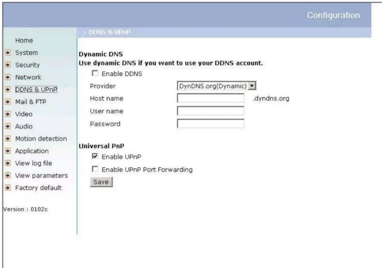
DDNS & UPnP
"Enable DDNS" This option turns on the DDNS function.
“Provider” The provider list contains four hosts that provide DDNS services. Please connect to the service provider’s website to make sure the service charges.
"Host Name" If the User wants to use DDNS service, this field must be filled. Please input the hostname that is registered in the DDNS server.
“Username/ E-mail” The Username or E-mail field is necessary for logging in the DDNS server or notify the User of the new IP address. Note: when this field is input as “Username” the following field must be input as “Password”.
"Password/ Key" Please input the password or key to get the DDNS service.
“Enable UPnP” This turns on or off the UPnP function. When UPnP is turned off, the camera cannot be found through network neighbors in MS Windows XP. If the UPnP network component is installed in Windows XP, the hostname of the Network Camera will be shown with bracketed IP address in the Network neighbors. Ex: Network Camera with Pan/Tilt (xxx.xxx.xxx.96). That is: The hostname of the Network Camera is “Network Camera with Pan/Tilt”, and the IP address of the Network Camera is xxx.xxx.xxx.96, depends on the last value of the IP address assigned to the Network Camera.
“Enable UPnP Port Forwarding” This turns on or off the UPnP port forwarding function. If your camera is behind an NAT router and your router supports UPnP port forwarding, turn on this option will help you to access your camera.
"Save" Click on this button to save current settings for the DDNS service and UPnP function.
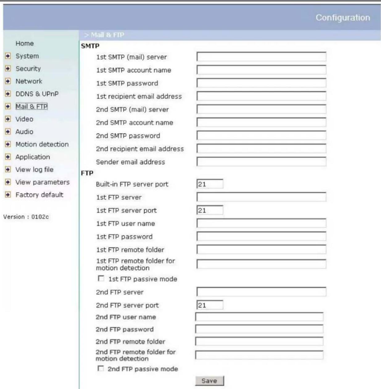
Mail & FTP
SMTP
"1st SMTP (mail) server" The domain name or IP address of the external email server.
"1st SMTP account name" Granted account name on the email server.
"1st SMTP password" Granted password on the email server.
"1st recipient email address" The email address of recipients for snapshots or log file. Multiple recipients must be separated by semicolon, ‘;’.
"2nd SMTP (mail) server" The domain name or IP address of another email server once the previous server is unreachable.
"2nd SMTP account name" Granted account name on the backup SMTP server.
"2nd SMTP password" Granted password on the backup SMTP server.
"2nd recipient email address" The email address of recipients for the backup server.
"Sender email address" The return email address used in the event the mails fail to send out.
FTP
“Built-in FTP server port” This can be other than the default Port 21. The User can change this value from 1 to 65535. After the change, the external FTP client program must change the server port of connection accordingly.
"1st FTP server" The domain name or IP address of the external FTP server. The following user settings must be correctly configured for remote access.
"1st FTP server port" The port to access the external FTP server.
"1st FTP user name" Granted user name on the external FTP server.
"1st FTP password" Granted password on the external FTP server.
"1st FTP remote folder" Granted folder on the external FTP server. This folder is for system log information and for images captured due to sequential operation or digital
input events. The string must conform to that of the external FTP server. Some FTP servers cannot accept preceding slash symbol before the path without virtual path mapping. Refer to the instructions for the external FTP server for details. The folder privilege must be open for upload.
"1st FTP remote folder for motion detection" Granted folder on the external FTP server. This folder is for images captured due to motion detection events. The string must conform to that of the external FTP server. Some FTP servers cannot accept preceding slash symbol before the path without virtual path mapping. Refer to the instructions for the external FTP server for details. The folder privilege must be open for upload.
"1st FTP passive mode" The Network Camera is located inside the network protected by a firewall, data connection for FTP may be prohibited. By selecting passive mode, the FTP can bypass the rule and allow snapshot upload to proceed. If the passive mode is selected, the Network Camera can automatically attempt for active mode, if the external FTP server does not support passive mode.
"2nd FTP server" The domain name or IP address of the backup FTP server.
"2nd FTP server port" The port to access the backup FTP server.
"2nd FTP user name" Granted user name on the backup FTP server.
"2nd FTP password" Granted password on the backup FTP server.
"2nd FTP remote folder" Granted folder on the backup FTP server. This folder is for system log information and for images captured due to sequential operation or digital input events.
"2nd FTP remote folder for motion detection" Granted folder on the external FTP server. This folder is for images captured due to motion detection events.
"2nd FTP passive mode" Passive mode setting for the backup FTP server.
Video Codec Parameters
"Text on video" The text will be displayed in the black bar above the video window with a timestamp. The timestamp is captured from date and time of the Network Camera that is maintained by a built-in real-time clock.
"Color" Select either for color or monochrome video display.
"Size" There are five options for three video sizes. "Half" is the quarter size of "Normal" and "Normal" is the quarter size of "Double". "Half x 2" has the same video size as "Normal" but of a lesser quality, while consuming less network bandwidth. "Normal x 2" has the same size as "Double" but of a lesser quality.
"Video codec type" It can be either MJPEG or MPEG4. In MJPEG mode, the video frames are independent. In MPEG4 mode, there are I frames and P frames. To decode a P frame need the information of previous frame. MPEG4 consumes much less network bandwidth than MJPEG.
There are five dependent parameters provided for video performance adjustment. "Maximum frame rate" This limits the maximal refresh frame rate, which can be combined with the "Video quality control" to optimize the bandwidth utilization and video quality. If the User wants to fix the bandwidth utilization regardless of the video quality, choose "Fix bit rate" and select the desired bandwidth. MPEG4 video are composed by I frames and P frames as the following sequence. IPPPPPIPPPPPIPPPP... "Key frame interval" determines how many repeated P frames will appear after one I frame. Large "Key frame interval" can reduce the bit rate, but cause image corrupt longer if there is packet loss while transmission. "Fix bit rate" option and "Key frame interval" option are only available in "MPEG4" mode. The video quality may be poor due to the sending of maximal frame rate within the limited bandwidth when images are moving rapidly. Consequently, to ensure detailed video quality (quantization rate) regardless of the network, it will utilize more bandwidth to send the maximal frames when images change drastically.
"Flip" Vertically rotate the video.
"Mirror" Horizontally rotate the video. Check options both if the Network Camera is installed upside down.
"I improve efficiency in the multi-user environment" Check this option to
improve efficiency in the multi-user environment when running in the low bandwidth environment. But it will cause each connection slow a few minutes when connection established.
"Time stamp on video" When selected the time stamp format is:
a) "Size" becomes Normal or Double, "Text on video hh:mm:ss yyyy/mm/dd" b) "Size" becomes half, "hh:mm:ss yyyy/mm/dd"
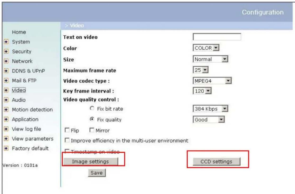
Image Settings
Click on "Image Settings" to pop up another window for tuning "Brightness",
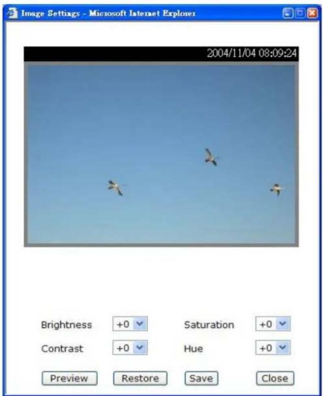
"Contrast", "Hue" and "Saturation" for video compensation.
Each field has eleven levels ranged from -5 to +5. The User may press "Preview" to fine-tune the image. When the image is O.K., press "Save" to set the image settings. Click on "Restore" to recall the original settings without incorporating the changes.
CCD Settings
Click on "CCD Settings" button, the CCD settings window will pop up.
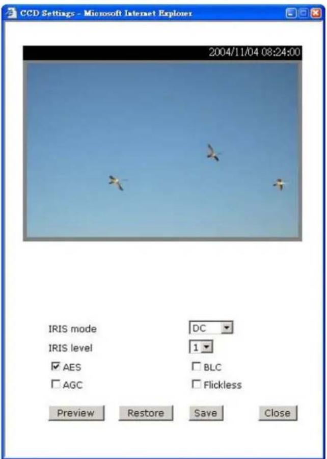
"IRIS mode" selection allows you to select between DC drive or Video drive to fit your auto iris lens.
"I RIS level" let users to adjust the aperture size of your auto iris lens.
"AES" - auto electronic shutter, enable this will let CCD sensor adjust electronic shutter automatically. Disable this when auto iris lens is attached.
"BLC" - back light compensation, enable this will help to identify objects in front of light source.
"AGC" - automatic gain control, enable this to do MAX AGC, otherwise NORMAL AGC is done.
"Flickless" – enable this to fix the electronic shutter to (1/100 NTSC)(1/120 PAL).
Both IRIS mode and IRIS level work only when auto iris lens is attached. In the CCD settings window, click on "Preview" to see the effect of changing the options. Click on "Save" to set the CCD settings. Click on "Restore" to recall the original settings without incorporating the changes.
Audio
"Transmission mode" There are five options to select. For all the modes, only one client can talk to the server at the same time.
"Full-duplex (Talk and listen simultaneously)" In this mode, the User can talk to the server while listening sound from the server simultaneously.
"Half-duplex (Talk or listen, not at the same time)" In this mode, the User can talk to the server or listen from the server, but not at the same time.
"Simplex – Talk only" In this mode, the User can only talk to the server.
"Simplex – Listen only" In this mode, the User can only listen from the server.
"Disable" In this mode, the audio is disabled in both directions.
"Send audio from the active client to all the other clients" In half duplex transmission mode, select the option to talk to the server and broadcast your voice to all the other clients.
"I improve audio quality in low bandwidth environment" If the Network Camera works in versatile or low network bandwidth environment, the User can check this option to improving audio quality by sacrificing some real-time synchronization.
"Audio source" Select source from external or built-in microphone.
"Acoustic echo cancellation" In full-duplex mode, the server can play sound from the client and receive sound from the environment and send to client. Since the sound from the client is played by server, it will also be received by the server's microphone and send back to client. That is the client will hear its echo. Select this option can prevent echo by sacrificing the video frame rate.
“Bit rate” There are three kinds of bit-rate for audio. 32Kbps and 24Kbps are suitable for both music and speech like audio while 8Kbps are suitable for only speech like audio.
Configuration
Home
System
→ Security
Network
DDNS & UPnP
Mail & FTP
Video
Audio
Motion detection
Application
View log file
View parameters
→ Factory default
Version:0101a
>Audio
Transmission mode:
Full-duplex (Talk and listen simultaneously)
○ Half-duplex (Talk or listen, not at the same time)
Simplex (Talk only)
Simplex (Listen only)
○ Disable
Send audio from the active client to all the other clients:
C Yes (Only possible when transmission mode is half-duplex and bitrate is 8 Kbps)
No
Improve audio quality in low bandwidth environment:
C Yes
No
udio source:
Internal microphone
C External microphone
Acoustic echo cancellation:
C Enable
Disable
Bit rate: 8 Kbps
Save
Motion Detection
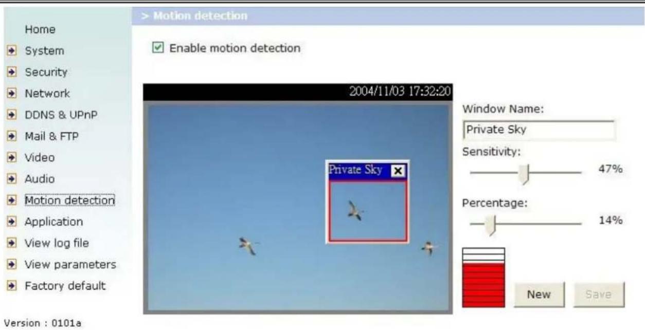
"Enable motion detection" Check this option to turn on motion detection.
New Click on this button to add a new window. At most three windows can exist simultaneously. Use the mouse to click, hold and drag the window frame to resize or the title bar to move. Clicking on the 'x' at the upper right-hand corner of the window to delete the window. Remember to save in order to validate the changes.
Save Click on this button to save the related settings. A graphic bar will rise or fall depending on the image variations. A green bar means the image variation is under monitoring level and a red bar means the image variation is over monitoring level. When the bar goes red, the detected window will also be outlined in red. Going back to the homepage, the monitored window is hidden but the red frame shows when motion is detected.
"Window Name" The text will show at the top of the window.
"Sensitivity" This sets the endurable difference between two sequential images.
“Percentage” This sets the space ratio of moving objects in the monitoring window. Higher sensitivity and small percentage will allow easier motion detection.
Application Setup
Weekly Schedule
"Sun" \~ "Sat" Select the days of the week to perform the following operations.
"Snapshots begin at" Set the time to start operations.
"Snapshots stop at" Set the time to stop operations. Setting identical begin time and stop time means 24-hour operation.
"All the time except for the above schedule" Invert the selected schedule. The default setting of this option is checked.
"Snapshot file name prefix" Specify the prefix name for the snapshot file. Please check naming rule of snapshot file for more detail.
Event Operation
“Delay second(s) before detecting next event” Set the time delay before restarting to check on the triggering condition when the current condition is triggered.
"Send pre-event image(s) when event occurs" Specify how many pre-event snapshot will be sent if events happen.
“Trigger condition” There are four conditions relative to the digital input and three windows for motion detection. More than one condition can be selected at once. Select the appropriate digital input condition that suits the characteristics of the external device. “high”, “low” selects level-triggering via external voltage input. “rising”, “falling” is for edge-triggering. There are three windows for motion detection each can be assigned a name. If motion detection has not been set up, it will not be shown. If this happens, clicking on “Motion detection” and a note will show to direct the User to the configuration page for motion detection.
"Trigger action" There are four options for two types of action. More than one condition can be selected at once. While choosing to trigger an output alarm, the
digital output will short both pins and complete the external device's circuit. The normal state is open. Either email or FTP can be used to command uploading snapshots. The date and time suffix may also be added as an option. Confirm the external mail or FTP server settings in the network configuration.
"Reset output" Select and save this option to reset the external device at the digital output to return to the original state.
Sequential Operation
“Snapshot interval” The Network Camera will send snapshots at the specified intervals to the external server.
"Send snapshots by email" This selects the uploading method following the intervals set above. The snapshot will be attached in the email with the subject title "Periodic snapshots".
"Send snapshots by FTP" The snapshots will be uploaded to the external FTP server with the file name defined in the next option. This can also be used to refresh the captured images stored in the external web server to build creative homepages.
“FTP put snapshots with date and time suffix” This option sets up the snapshot capture date and time, which can be used to easily differentiate the snapshot file names in either the sequential or event operation. Please check naming rule of snapshot file for more detail.
©
![Configuration Home System Security Network DDNS & UPnP Mail & FTP Video Audio Motion detection Application View log file View parameters Factory default Version : 0101a > Application Weekly schedule Sun Mon Tue Wed Thu Fri Sat snapshots begin at 00:00:00 [hh:mm:ss] snapshots stop at 00:00:00 [hh:mm:ss] ✓ All the time except for the above schedule Snapshot file name prefix video Event operation General Delay 3 second(s) before detecting the next event Send 1 pre-event image(s) when event occurs Trigger condition Input is high Input is low Input is rising Input is falling Detect motion in : Note: Motion detection must be setup first Trigger action Trigger output alarm while input condition matched Trigger output alarm while motion detected Upload snapshots while input condition matched Upload snapshots while motion detected Reset output Sequential operation Snapshot interval: 1 Second(s) Send snapshots by email Send snapshots by FTP ✓ FTP put snapshots with date and time suffix Save](/content/2026/06/1146004/images/40e4cfeb6de778bf8004879c795da62fcf2add528d0fc0771cb4b17559c768cc.jpg)
Viewing System Log
Click on the link on the configuration page to view the system log file. The content of the file provides useful information about configuration and connections after system boot-up.
Viewing System Parameters
Click on this link on the configuration page to view the entire system's parameter set. The content is the same as those in CONFIG.INI.
Factory Default
"Factory default"
Click on this link on the configuration page to restore factory default settings. Any changes made so far will be lost and the system will be reset to the initial factory settings. After clicking on the "Restore" button and make confirmation, the system will restart and require the installer program to set up the network again.
Appendix
A. Troubleshooting
Status LED
After powering up, the Network Camera performs a self-diagnostic to detect any hardware defects. The following table lists the LED patterns in general. In case of any fatal error, the LED will blink in a pattern other than those below.
| Condition | LED color |
| During self-diagnostic after power on blink between red and green | |
| No network Red is ON | |
| Getting IP Green is flash every 0.5 sec | |
| Talk only / mute Green is flash every 1 sec | |
| Listen only / Full duplex / half duplex | Green is flash every 0.5 sec |
natural_image
Line drawing of a mounted electronic device with a red arrow pointing to the top component (no text or symbols present)Reset and Restore
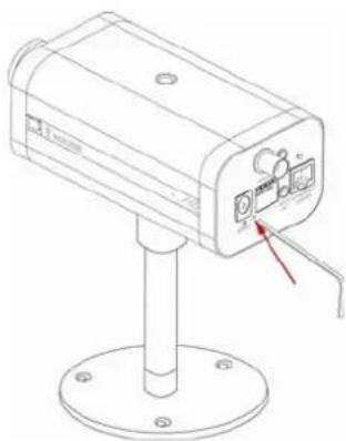
At the left side of the camera there is a button hidden in the pinhole as shown in the picture. It is used to reset the system or restore the factory default settings. Sometimes resetting the system sets the system back to normal state. If the system problems remain after reset, restore the factory settings and install again.
RESET: Poke the wrench to click on the button.
!Restoring the factory defaults will erase any previous settings. Reset or restore the system after power on.
RESTORE: 1. Poke the wrench to press on the button continuously.
-
Wait for self-diagnostic until the LED turns orange.
-
Withdraw the wrench.
B. Frequently Asked Questions
Q What if I forget my password?
After the Administrator's password has been assigned, every access to the Network Camera needs authentication. If you are one of the managed users, you have to ask the Administrator for the password. If you are the Administrator, there is no way to recover the root password except by restoring the factory default settings. Refer to Appendix A for the procedures.
Q Why can I not watch video from the Network Camera after it is authenticated?
A There are many possible scenarios regarding this problem,
-
If you have just installed the Network Camera and are unable to watch the video, check if the heartbeat LED is blinking or the lens cap is off. If the heartbeat LED is dim, perform the software installation again.
-
If the Network Camera is well installed and you are accessing the Network Camera for the first time using Internet Explorer, adjust the security level of Internet Explorer to allow installation of plug-ins.
-
If the problem still exists after adjusting, and the message over the image window is showing "connecting", the network traffic may be too crowded.
-
It there is only "A" shown below the image, check the media options in client settings containing video.
Q What is the plug-in for?
A The plug-in provided by the Network Camera is used to display motion pictures and audio in Internet Explorer. If your system does not allow installation of any plug-in software, the security level of the web browser may need to be lowered. It is recommended that you consult your network supervisors in your office regarding adjustment of the security level. Software installation may be regulated in some offices.
Q Why is the timestamp different from the system time of my PC or notebook?
A The timestamp is based on the system time of the Network Camera. It is maintained by a real-time clock inside and can be automatically synchronized with
the time-server if the Network Camera is connected to the Internet and the function is enabled. Differences of several hours may result from the time zone setting.
Q Can I install it on ceiling?
A Yes. There are flip and mirror options in video configuration page to correct the images for upside down installation.
Q The image is not clear enough.
A Rotate the lens to adjust the focus after the Network Camera has been installed in the proper position. The image settings and white balance can be fine tuned to achieve the best visual effect. Also notice the power line frequency must match the local utility to synchronize and minimize the effect of flickering florescent lights.
Q Why does the image not refresh regularly?
A Some anti-virus programs filter the received web content. It takes time to perform data examination and affect the streaming application such as that of Network Camera. However, it only affects the HTTP mode of Network Camera. If the network allows only HTTP mode, disable the web filtering function of the anti-virus program temporarily. During this period, the User should be aware of the risk of malicious network activity.
Q I have opened motion detection windows but it cannot work.
A If the motion detection windows are set up and names are given, check to see if the function is checked on the first line. While it is enabled, adjust the sensitivity and percentage to monitor the level indicator for best results.
Q I cannot hear any sound while watching.
A If there is "V" shown below the image, check the sound card in your PC and make sure media options in client settings containing audio. If "AV" is shown, check the audio source of the Network Camera, make sure you are using internal or external microphone.
Q How many users are allowed to watch the Network Camera at the same time?
A Too many users requesting the real-time multimedia content will jam the network. For best results, the Network Camera is designed to accommodate a maximum of ten (10) users to watch and listen for streaming video and audio at the same time. For a larger number of users, it is recommended to build another web server to host the retrieved contents from the Network Camera.
Q How fast is the video rate of the Network Camera?
A The MPEG4 codec engine can process up to 30 frames per second internally. However the total performance is subject to many coefficients such as:
- Network throughput,
- Bandwidth share,
- Number of users,
- The complicated/detailed objects and movement in view,
- The power of your PC or notebook that is responsible for displaying images.
In general, the transfer rate in a general local network environment can achieve over 200 kilobytes per second and approximately 10 to 20 pictures per second from a regular environment.
Q How can I keep the Network Camera as private as possible?
A The Network Camera is designed for surveillance purposes and has many flexible interfaces. The user authentication and special confirmation in installation can keep the Network Camera from unauthorized access. You may also change the HTTP port to a non-public number. The demo account is good to separate guests from normal users and thus you can easily block guests anytime. You can check the system log to examine any abnormal activities and trace the origins.
Why can I not access the Network Camera when I setup some options in the application?
A Since the Network Camera is a "network camera", any incorrect network settings will make it inaccessible. If this happens, restore the factory default settings following the procedures in Appendix A.
C. URL commands of Network Camera
For some customers who already have their own web site or web control application, Network Camera can be easily integrated through convenient URLs. This section lists the commands in URL format corresponding to the basic functions of Network Camera.
Overview
This section specifies the external HTTP based application programming interface. The HTTP based camera interface provides the functionality to request a single image, to control camera functions (output relay etc.) and to get and set internal parameter values. The image and CGI-requests are handled by the built in Web server.
Style convention
In URL syntax and in descriptions of CGI parameters, a text in italic within angle brackets denotes a content that is to be replaced with either a value or a string. When replacing the text string also the angle brackets shall be replaced. An example of this is the description of the name for the server, denoted with
URL syntax' are written with the "Syntax:" word written in bold face followed by a box with the referred syntax as seen below. The name of the server is written as
Syntax:
http://
Description of returned data is written with "Return:" in bold face followed by the returned data in a box. All data returned as HTTP formatted, i.e., starting with the string HTTP is line separated with a Carriage Return and Line Feed (CRLF) printed as \r\n.
Return:
HTTP/1.0 <HTTP code> <HTTP text>\r\n
URL syntax examples are written with "Example:" in bold face followed by a short description and a light grey box with the example.
Example: request a single snapshot image
http://mywebserver/cgi-bin/video.jpg
General CGI URL syntax and parameters
CGI parameters are written in lower-case and as one word without any underscores or other separators. When the CGI request includes internal camera parameters, the internal parameters must be written exactly as they are named in the camera or video server. The CGIs are organized in function related directories under the cgi-bin directory. The file extension of the CGI is required.
Syntax:
http://<servername>/cgi-bin/<subdir>[/<subdir>...]/<cgi>.<ext>
[?<parameter>=<value>[&<parameter>=<value>...]]
Example: Setting digital output #1 to high
http://mywebserver/cgi-bin/setparam.cgi?do1=h
Get server parameter values
Note: This request require administrator access
Method: GET/POST
Syntax:
http://<servername>/cgi-bin/admin/getparam.cgi?[<parameter>]
[&<parameter>...]
where the
When query parameter values, the current parameter value are returned.
Successful control requests returns paramter pairs as follows.
Return:
HTTP/1.0 200 OK\r\n
Content-Type: text/html\r\n
Context-Length: <length>\r\n
\r\n
<parameter pair>
where <parameter pair> is
<parameter> = <value> \r\n
[<parameter pair>]
Example: request IP address and it's response
Request:
http://192.168.0.123/cgi-bin/admin/getparam.cgi?network_ipaddress
Response:
HTTP/1.0 200 OK\r\n
Content-Type: text/html\r\n
Context-Length: 33\r\n
\r\n
network.ipaddress=192.168.0.123\r\n
Set server parameter values
Note: This request require administrator access
Method: GET/POST
Syntax:
http://<servername>/cgi-bin/admin/setparam.cgi?
[nosync=<value>&]<parameter>=<value>
[&<parameter>=<value>...] [&return=<return page>]
| parameter | value | description |
| nosync | 0, 1 Specifies that there should be no sync (write) of the corresponding configuration file on flash. If parameter is omitted, a sync write will occur.(note: this parameter must be put at begin of parameter list) | |
| value to assigned | Assignto the parameter_. | |
| return | Redirect to the pageafter the parameter is assigned. Thecan be a full URL path or relative path according the the current path. If you omit this parameter, it will redirect to an empty page.(note: The return page can be a general HTML file(.htm, .html) or a Vivotek server script executable (.vspx) file. It can not be a CGI command. It can not have any extra parameters. This parameter must be put at end of parameter list) | |
Return:
HTTP/1.0 200 OK\r\n
Content-Type: text/html\r\n
Context-Length: <length>\r\n
\r\n
<parameter pair>
where <parameter pair> is
<parameter> = <value> \r\n
[<parameter pair>]
Only the parameters that you set and readable will be returned.
Example: Set the IP address of server to 192.168.0.123
Request:
http://myserver/cgi-bin/admin/setparam.cgi?Network_IPAddress=192.168.0.123
Response:
HTTP/1.0 200 OK\r\n
Content-Type: text/html\r\n
Context-Length: 33\r\n
\r\n
network.ipaddress=192.168.0.123\r\n
Available parameters on the server
NOTE: The bold characters in table are the default value of each parameter.
Group: System
| NAME | VALUE | DESCRIPTION |
| hostname(r/w) | host name of server< <Wireless> Network Camera< with Pan/ Tilt/ >> | |
| (r/w) | 0 Do not turn off the | led indicator ledoff |
| 1 Turn off the led indicator | ||
| date(r/w) | year, month and date separated by slash. | |
| keep date | ||
| NTP to sync date/time automatically | ||
| time(r/w) | minute and second separated by colon. | |
| keep date | ||
| NTP to sync date/time automatically | ||
| ntp(r/w) | NTP server | |
| timezone(r/w) | -12 ~ 12 time zone, 8 | means GMT +8:00<8> |
| updateinterval(r/w) | 0 ~ 2592000 | 0 to Disable automatic time adjustment, otherwise, it means the seconds between NTP automatic update interval.<0> |
| serialnumber(r) | characters mac address without hyphen connected | |
| firmwareversion(r) | The version of firmware, including model, company, and version number | |
| restore(w) | 0 Restore the system parameters to default value. | |
| Positive integer Restore the system parameters to default value and restart the server afterseconds. | ||
| reset(w) | 0 ~ 65535 | Restart the server afterseconds. |
| -1 | Not restart the server. | |
unchar
unchar
| (w) | H - NC connected with COMMON do<1~4> | |
| L - NO connected with COMMON | ||
| (r) | H - NC connected with COMMON di<1~4> | |
| L - NO connected with COMMON | ||
| supportscriptversion (r) | The version of supported script/webpage | |
| scriptversion | string shorter than 10 characters > | The maximum version of currently installed script/webpage |
| language | string shorter than 16 characters > | The webpage language |
| webpageversion | text string shorter than 39 characters > | The version of webpage |
| 0 Turn on the IR control enableir(r/w) | ||
| 1 Turn off the IR control | ||
| ptzenabled (r) | 32-bit integer Indicate the operations of camera supported | |
Group: Security
| NAME | VALUE | DESCRIPTION |
| username_<1~20>(r/w) | change user name.<blank> | |
| userpass_<0~20>(r/w) | change user's password.The UserPass_0 is root's password.<blank> | |
| userattr_<1~20>(r/w) | [dido][|talk][|listen][|conf] | change user's privilege. The privilege can be the combination of dido – Permit I/O access talk – Permit to talk to server listen – Permit to listen from server conf – Permit to change server's configuration |
| usercount(r) | 1 ~ 21 | The current account number on the server including root.<1> |
Group: Network
| NAME | VALUE | DESCRIPTION |
| resetip(r/w)(restart) | 1 enable to get ipaddress, subnet, router,dns1, dns2 from DHCP s reboot | |
| 0 Using preset ipaddress, subnet, router,dns1, dns2 | ||
| ipaddress(r/w) (restart) | IP address of server<192.168.0.99> | |
| subnet(r/w) (restart) | subnet mask<255.255.255.0> | |
| router(r/w) (restart) | default gateway | |
| dns1(r/w) (restart) | primary DNS server | |
| dns2(r/w) (restart) | secondary DNS server | |
| smtp1(r/w) | primary SMTP server | |
| mailto1(r/w) | mail recipient address | |
| mailuser1(r/w) | User name of primary smtp server | |
| mailpass1(r/w) | Password of primary smtp server | |
| smtp2(r/w) | than 40 characters> | secondary SMTP server |
| mailto2(r/w) | mail recipient address | |
| mailuser2(r/w) | User name of secondary smtp server | |
| mailpass2(r/w) | Password of secondary smtp server | |
| returnemail(r/w) | return email address | |
| localftpport(r/w) | FTP port<21> | |
| ftp1(r/w) | primary FTP server | |
| ftpport1(r/w) | primary FTP port<21> | |
| ftpuser1(r/w) | user name for primary FTP server | |
| ftppass1(r/w) | password for primary FTP server | |
| ftpfolder1(r/w) | upload folder in primary FTP server | |
| (r/w) | 1 Enable passive mode | of primary FTP serverftppasvmode1 |
| 0 Disable passive mode | of primary FTP server | |
| ftp2(r/w) | secondary FTP server | |
| ftpport2(r/w) | secondary FTP port<21> | |
| ftpuser2(r/w) | user name for secondary FTP server | |
| ftppass2(r/w) | password for secondary FTP server | |
| ftpfolder2(r/w) | upload folder in secondary FTP server | |
| (r/w) | 1 Enable passive mode | of primary FTP serverftppasvmode2 |
| 0 Disable passive mode of primary FTP server | ||
| httpport(r/w) (restart) | HTTP port<80> | |
| videoport(r/w) (restart) | video Channel port for UDP<5003> | |
| audiport(r/w) (restart) | audio Channel port for UDP<5002> | |
Group: Video
| NAME | VALUE | DESCRIPTION |
| text(r/w) | enclosed caption | |
| (r/w) | 0 MPEG4 codectype | |
| 1 | MJPEG | |
| keyinterval(r/w) | 1, 3, 5, 10, 30, 60, 90, 120 | Key frame interval<120> |
| size(r/w) | 1 | half |
| 2 half x 2 | ||
| 3 normal | ||
| 4 normal x 2 | ||
| 5 | double | |
| (r/w) | 0 | monochrome color |
| 1 color | ||
| (r/w) | 0 fix bit rate quality | |
| 1 fix quantization | ||
| quant 1 lowest quality of video | ||
| (r/w) | 2 lower quality of video | |
| 3 normal quality of video | ||
| 4 higher quality of video | ||
| 5 highest quality of video | ||
| bitrate (r/w) | 64000 set bit rate to 64K bps | |
| 128000 set bit rate to 128K bps | ||
| 256000 set bit rate to 256K bps | ||
| 384000 set bit rate to 384K bps | ||
| 512000 set bit rate to 512K bps | ||
| 768000 set bit rate to 768K bps | ||
| 1000000 set bit rate to 1000K bps | ||
| 1200000 set bit rate to 1200K bps | ||
| maxframe (r/w) | 1 set maximum frame rate to 1 fps | |
| 2 set maximum frame rate to 2 fps | ||
| 3 set maximum frame rate to 3 fps | ||
| 5 set maximum frame rate to 5 fps | ||
| 10 set maximum frame rate to 10 fps | ||
| 15 set maximum frame rate to 15 fps | ||
| 20 set maximum frame rate to 20 fps | ||
| 25 set maximum frame rate to 25 fps | ||
| 30 (for NTSC only) set maximum frame rate to 30 fps | ||
| modulation (r/w)(in server version only) (restart) | 0 | NTSC |
| 1 | PAL | |
| 2 | AUTO | |
| (r) (in built-in CCD version only) | 0 | NTSC actualmodulation |
| 1 | PAL | |
| (r/w) | 1 | flip image |
| 0 normal image | ||
| mirror | 1 | mirror image |
| (r/w) 0 normal image | ||
| (r/w) | 1 Overlay time stamp | on video imprinttimestamp |
| 0 Do not overlay time | stamp on video | |
| 1 Enable udp slow start udpslowstart | ||
| 0 Disable udp slow start | ||
Group: Audio
| NAME | VALUE | DESCRIPTION |
| bitrate (r/w) | 8000 set bitrate to 8K bps | |
| 24000 set bitrate to 24K bps | ||
| 32000 set bitrate to 32K bps | ||
| transfermode (r/w) | 0 Full-duplex (Talk & Listen simultaneously) | |
| 1 Half-duplex (Talk or Listen, not at the same time) | ||
| 2 Simplex – Talk only | ||
| 3 Simplex – Listen only | ||
| 4 | Disable audio | |
| sendclientaudio (r/w) | 0 Do not send audio from active client to all other clients | |
| 1 | Send audio from active client to all other clients (only possible in Half-duplex) | |
| 0 Use external microphone in | ||
| 1 Use build microphone | ||
| lowbandwidth (r/w) | 0 Disable low bandwidth environment support | |
| 1 Improve in low bandwidth environment | ||
| (r/w) | 0 Disable | |
| 1 | Enable | |
Group: Image
| NAME | VALUE | DESCRIPTION |
| brightness(r/w) | <-5 ~ 5> | Adjust brightness of image according tomode |
| saturation (r/w) | <-5 ~ 5> Adjust saturation of image according to mode settings. <0> | |
| contrast (r/w) | <-5 ~ 5> Adjust contrast of image according to mode settings. <0> | |
| hue (r/w) | <-5 ~ 5> Adjust hue of image according to mode settings. <0> | |
| mode (w) | Preview Apply the parameter of image but not save | |
| Restore Restore the last saved image parameters | ||
| Save Directly save the adjust image parameters | ||
setting:
Group: CCD
| NAME | VALUE | DESCRIPTION |
| (r/w) | Video | Video Iris |
| DC DC Iris | ||
| irislevel (r/w) | <1 ~ 8> | Iris level when connect to auto iris lens. 1 => most brightness, 8 => most darkness <1> |
| autoelectronicshutter (r/w) | 0 | Turn off AES |
| 1 | Turn on AES | |
| enableblc (r/w) | 0 | Turn off backlight compensation |
| 1 | Turn on backlight compensation | |
| enableagc (r/w) | 0 | Set auto gain control to normal level |
| 1 | Set auto gain control to MAX level | |
| flickless (r/w) | 0 | Turn off flickless |
| 1 | Turn on flickless (1/100 NTSC, 1/120 PAL) | |
| update (w) | 1 | Update the above settings |
| mode(w) | Preview Apply the p | parameter of image but not save |
| Restore Restore | the last saved image parameters | |
| Save Directly save | the adjust image parameters |
Group: Motion
| NAME | VALUE | DESCRIPTION |
| (r/w) | 0 disable motion detection enabled | |
| 1 enable motion detection | ||
| >(r/w) | 0 disable motion window # 1 winenabled_<1~3 | |
| 1 enable motion window # 1 | ||
| winname_<1~3>(r/w) | name of motion window # 1 | |
| winleft_<1~3>(r/w) | 0 ~ 352 for CCD0 ~ 320 for CMOS | Left coordinate of window position.<0> |
| wintop_<1~3>(r/w) | 0 ~ 288 for PAL0 ~ 240 forNTSC & CMOS | Top coordinate of window position.<0> |
| winwidth_<1~3>(r/w) | 0 ~ 352 for CCD0 ~ 320 for CMOS | Width of motion detection window.<0> |
| winheight_<1~3>(r/w) | 0 ~ 288 for PAL0 ~ 240 forNTSC & CMOS | Height of motion detection window.<0> |
| winobjsize_<1~3>(r/w) | 0 ~ 100 Percent of motion detection window<0> | |
| winsensitivity_<1~3>(r/w) | 0 ~ 100 Sensitivity of motion detection window<0> | |
| update(w) | 1 Update the above | motion detectionsettings to take effect |
Group: DDNS
| NAME | VALUE | DESCRIPTION |
| enable(r/w) | 0, 1 Enable or disable the dynamic dns.<0> | |
| provider(r/w) | 1 ~ 4 dyndns.org (dynamic)dyndns.org (custom)tzo.comdhs.org<1> | |
| hostname(r/w) | Text string shorter than 127 characters. | Your dynamic hostname.<blank> |
| usernameemail(r/w) | Text string shorter than 63 characters. | Your user or email to login ddns service provider<blank> |
| passwordkey(r/w) | Text string shorter than 20 characters. | Your password or key to login ddns service provider<blank> |
| update(w) | 0, 1 Update the above ddns settings to take effect |
Group: UPNP
| NAME | VALUE | DESCRIPTION |
| enable (r/w) | 0, 1 Enable or disable the UPNP service. <1> | |
Group: App
| NAME | VALUE | DESCRIPTION |
| scriptname < text string shorter than File name of script | ||
| (r/w) | 255 characters> | <script.vssx> |
| (r/w) | 0 | Disable script |
| 1 Enable script | ||
Group: Feature
| NAME | VALUE | DESCRIPTION |
| (r/w) | 0 | event |
| 1 | support motion loss information in video bitstream |
Application page CGI command
Note: This request requires administrator privilege.
Method: GET/POST
Syntax:
http://<servername>/setup/app.vspx?[method=<value>][&sun=<value>]
[&mon=<value>]
[&tue=<value>][&wed=<value>][&thu=<value>][&fri=<value>][&sat=<value>]
[&begin_time=<value>][&end_time=<value>][&exclude=<value>]
[&eventop=<value>]
[&delay=<value>][&prevnum=<value>][&ssfprefix=<value>][&dihigh=<value>]
[&dilow=<value] [ &dirise=<value> ] [ &difall=<value> ] [ &motion1=<value]
[ &motion2=<value> ] [ &motion3=<value> ] [ &ioalarm=<value> ]
[ &mdalarm=<value]
[ &iupload=<value> ] [ &mdupload=<value> ] [ &seqop=<value> ] [ &sinter=<value> ]
[ &smethod=<value> ] [ &suffix=<value> ] [ &resetdo=<value> ]
Return:
HTTP/1.0 200 OK\r\n
Content-Type: text/plain\r\n
Content-Length: <length>\r\n
\r\n
<depends on method value>
If(method == get || method == set)
{
    tue=<value>\r\n
    wed=<value>\r\n
    ...
}
Else if(method == normal)
{
    Application page contents
}
| parameter | Value description | |
| method | get Get parameters, if no parameter followed, all the parameters value will be listed. Otherwise, it will list followed parameter value. | |
| set | Set parameters | |
| normal Display normal application page contents | ||
| sun | 0/1 Disable/Enable Sunday weekly schedule check box | |
| mon | 0/1 Disable/Enable Monday weekly schedule check box | |
| tue | 0/1 Disable/Enable Tuesday weekly schedule check box | |
| wed | 0/1 Disable/Enable Wednesday weekly schedule check box | |
| thu | 0/1 Disable/Enable Thursday weekly schedule check | |
| box | ||
| fri | 0/1 Disable/Enable | Friday weekly schedule check box |
| sat | 0/1 Disable/Enable | Satday weekly schedule check box |
| begin_time | hh:mm:ss Begin | time of weekly schedule |
| end_time | hh:mm:ss End time | time of weekly schedule |
| exclude | 0/1 Disable/Enable | all the time except for the above schedule check box |
| eventop | 0/1 Disable/Enable | Event operation |
| delay | 1~999 Delay seconds before detect next event | |
| prevnum | 0~6 Number of pre-trigger event images | |
| ssfprefix | Snapshot file name prefix for both event and sequential operation | |
| dihigh | 0/1 Enable/Disable | trigger when input is high |
| dilow | 0/1 Enable/Disable | trigger when input is low |
| dirise | 0/1 Enable/Disable | trigger when input is rising |
| difall | 0/1 Enable/Disable | trigger when input is falling |
| motion1 | 0/1 Enable/Disable | trigger when motion int window #1 is detected |
| motion2 | 0/1 Enable/Disable | trigger when motion int window #2 is detected |
| motion3 | 0/1 Enable/Disable | trigger when motion int window #3 is detected |
| ioalarm | 0/1 Enable/Disable | DO trigger when DI condition matched |
| mdalarm | 0/1 Enable/Disable | DO trigger when motion detection condition matched |
| iupload | 0/1 Enable/Disable | upload snapshot when DI condition matched |
| mdupload | 0/1 Enable/Disable | upload snapshot when motion detection condition matched |
| seqop | 0/1 Enable/Disable sequential operation |
| sinter | 1 ~ 99999 Interval of sequential snapshot in second |
| smethod | mail Send snapshot by e-mail |
| ftp Send snapshot by ftp | |
| suffix | 0/1 Enable/Disable FTP put snapshots with date and time suffix |
| resetdo | 0/1 Reset/No reset DO when click save button |
Example: Enable sequential send snapshot by every 1 second with email.
http://myserver/setup/app.vspx?method=set&exclude=1&eventop=0&seqop=1&smethod=mail&sinter=1
Drive the digital output
Note: This request requires the privilege of I/O access control.
Method: GET/POST
Syntax:
http://<servername>/cgi-bin/setdo.cgi?do1=<state>[&do2=<state>][&do3=<state>][&do4=<state>][&return=<return page>]
Where state is H, L. H means NC (normal close) connected with COMMON and L means NO (normal open) connected with COMMON. The number of DO dependents on the server type.
| parameter | Value | description |
| do | H – NC connected with COMMON | |
| L – NO connected with COMMON | ||
| return | Redirect to the pageafter the parameter is assigned. Thecan be a full URL path or relative path according the the current path. If you omit this parameter, it will redirect to an empty page. |
Example: Drive the digital output 1 to high and redirect to an empty page
http://myserver/cgi-bin/setdo.cgi?do1=H
Query status of the digital input
Note: This request requires the privilege of I/O access control.
Method: GET/POST
Syntax:
http://
If no parameter is specified, all the status of digital input will be returned.
Return:
HTTP/1.0 200 OK\r\n
Content-Type: text/plain\r\n
Content-Length: <length>\r\n
\r\n
[di1=<state>]\r\n
[di2=<state>]\r\n
[di3=<state>]\r\n
[di4=<state>]\r\n
where
Example: Query the status of digital input 1
Request:
http://myserver/cgi-bin/getdi.cgi?di1
Response:
HTTP/1.0 200 OK\r\n
Content-Type: text/plain\r\n
Content-Length: 7\r\n
\r\n
di1=H\r\n
Query status of the digital output
Note: This request requires the privilege of I/O access control.
Method: GET/POST
Syntax:
http://<servername>/cgi-bin/getdo.cgi?[do1][&do2][&do3][&do4]
If no parameter is specified, all the status of digital output will be returned.
Return:
HTTP/1.0 200 OK\r\n
Content-Type: text/plain\r\n
Content-Length:
\r\n
[do1=
[do2=
[do3=
[do4=
where
Example: Query the status of digital output 1
Request:
http://myserver/cgi-bin/getdo.cgi?di1
Response:
HTTP/1.0 200 OK\r\n
Content-Type: text/plain\r\n
Content-Length: 7\r\n
\r\n
do1=H\r\n
Capture single snapshot
Note: This request require normal user privilege
Method: GET/POST
Syntax:
http://<servername>/cgi-bin/video.jpg
Server will return the most up-to-date snapshot in JPEG format. The size and quality of image will be set according to the JPEG settings on the server.
Return:
HTTP/1.0 200 OK\r\n
Content-Type: image/jpeg\r\n
[Content-Length: <image size>\r\n]
<binary JPEG image data>
Account management
Note: This request requires administrator privilege
Method: GET/POST
Syntax:
http://
method=
[ &privilege=
| parameter | value description | |
| method | add Add an account to server. When using this method, “username” field is necessary. It will use default value of other fields if not specified. | |
| delete Remove an account from server. When using this method, “username” field is necessary, and others are ignored. | ||
| edit Modify the account password and privilege. When using this method, “username” field is necessary, and other fields are optional. If not specified, it will keep original settings. | ||
| username | The name of user to add, delete or edit | |
| userpass | The password of new user to add or that of user to modify. The default value is an empty string. | |
| privilege | The privilege of user to add or to modify. The privilege can be the addition of the following values. Ex: A user with DI/DO access and listen privilege can be assigned privilege as privilege= dido&privilege= listen. | |
| dido DI/DO access privilege | ||
| listen | listen privilege | |
| talk | talk privilege | |
| camctrl camera control privilege (support only on PT(Z) version) | ||
| conf | configuration privilege | |
| return | Redirect to the pageafter the parameter is assigned. Thecan be a full URL path or relative path according the the current path. If you omit this parameter, it will redirect to an empty page. | |
System logs
Note: This request require administrator privilege
Method: GET/POST
Syntax:
http://<servername>/cgi-bin/admin/syslog.cgi
Server will return the up-to-date system log.
Return:
HTTP/1.0 200 OK\r\n
Content-Type: text/plain\r\n
Content-Length:
\r\n
Configuration file
Note: This request requires administrator privilege
Method: GET/POST
Syntax:
http://
Server will return the up-to-date configuration file.
Return:
HTTP/1.0 200 OK\r\n
Content-Type: text/plain\r\n
Content-Length: <configuration file length>\r\n\r\n
<configuration data>\r\n
System Information
Note: This request requires normal user privilege
Method: GET/POST
Syntax:
http://<servername>/cgi-bin/sysinfo.cgi
Server will return the system information.
Return:
HTTP/1.0 200 OK\r\n
Content-Type: text/plain\r\n
Content-Length: <system information length>\r\n
\r\n
Model=<model name of server>\r\n
HostName=<host name of server>\r\n
Location=<video on text of server>\r\n
[Preset<0>=<first preset location>\r\n]
[Preset<1>=<second preset location>\r\n]
[...]
PTZEnabled=<PTZ status>\r\n
Where the
Bit 0 => Support camera control function 0(not support), 1(support)
Bit 1 => Build-in or external camera. 0(external), 1(build-in)
Bit 2 => Support pan operation. 0(not support), 1(support)
Bit 3 => Support tilt operation. 0(not support), 1(support)
Bit 4 => Support zoom operation. 0(not support), 1(support)
Bit 5 => Support focus operation. 0(not support), 1(support)
D. Technical Specifications
- System
CPU: Trimedia PNX1300
RAM: 16MB SDRAM
ROM: 4MB FLASH ROM
- Networking
Protocol
TCP/IP, HTTP, SMTP, FTP, Telnet, NTP, DNS UPnP, DDNS and DHCP
Physical
10BaseT Ethernet or 100BaseT Fast Ethernet Auto negotiation
- Video
Algorithm supported
MPEG4 simple profile/MJPEG selectable
JPEG for still image
Features
Adjustable image size, quality and bit rate
Timestamp and text overlay
3 motion detection windows
Resolution
Up to 30/25 frames at 176x120 or 176x144
Up to 30/25 frames at 352x240 or 352x288
Up to 15/12 frames at 704x480 or 704x576
- Camera specification
1/3 inch color CCD sensor
Typical: 0.5 Lux / F2.0
AGC, AWB, AES
Electronic shutter: 1/60(1/50) to 1/100,000 sec
- Lens
CS mount
F2.0, f=6.0mm
- Audio
32Kbps, 24Kbps, 8Kbps
Acoustic echo cancellation
Full duplex audio communication
- Microphone
Omni-directional
Frequency: 20 - 20,000Hz
S/N ratio: more than 58dB
- General I/O
1 sensor input max.12VDC 50mA
1 relay output max. 24VDC 1A, 125VAC 0.5A
- LED indicator
Dual color syatem status indicators
- Weight
NET. 430g
- Dimension
140 mm(L) * 70mm(W) * 55 mm(H)
- Power
Consumption: MAX 7.0 W
Adapter input: 100-240VAC, 50/60Hz, 0.4A
Adapter output: 12VDC, 1.5A
- Operating Environment
Temperature: 0-40°C/32-102°F
Humidity: 85% RH
-EMI & Safety
CE, FCC
- Viewing system requirement
Operating System
Microsoft Windows 98SE/ME/2000/XP
Browser
Internet Explorer 5.x or above
Technology License Notice
MPEG-4 Visual Technology
This product includes one MPEG-4 encoder and one MPEG-4 decoder license. Installation of more than one decoder is prohibited. Please contact your reseller to purchase additional decoder licenses.
THIS PRODUCT IS LICENSED UNDER THE MPEG-4 VISUAL PATENT PORTFOLIO LICENSE FOR THE PERSONAL AND NON-COMMERCIAL USE OF A CONSUMER FOR (i) ENCODING VIDEO IN COMPLIANCE WITH THE MPEG-4 VISUAL STANDARD ("MPEG-4 VIDEO") AND/OR (ii) DECODING MPEG-4 VIDEO THAT WAS ENCODED BY A CONSUMER ENGAGED IN A PERSONAL AND NONCOMMERCIAL ACTIVITY AND/OR WAS OBTAINED FROM A VIDEO PROVIDER LICENSED BY MPEG LA TO PROVIDE MPEG-4 VIDEO. NO LICENSE IS GRANTED OR SHALL BE IMPLIED FOR ANY OTHER USE. ADDITIONAL INFORMATION INCLUDING THAT RELATING TO PROMOTIONAL, INTERNAL AND COMMERCIAL USES AND LICENSING MAY BE OBTAINED FROM MPEG LA, LLC. SEE HTTP://WWW.MPEGLA.COM.
Electromagnetic Compatibility (EMC)
This device compiles with FCC Rules Part 15. Operation is subject to the following two conditions.
This device may not cause harmful interference, and
This device must accept any interference received, including interference that may cause undesired operation.
This equipment has been tested and found to comply with the limits for a Class B digital device, pursuant to Part 15 of the FCC Rules. These limits are designed to provide reasonable protection against harmful interference in a residential installation. This equipment generates, uses, and can radiate radio frequency energy and, if not installed and used in accordance with the instructions, may cause harmful interference to radio communications. However, there is no guarantee that interference will not occur in a partial installation. If this equipment does cause harmful interference to radio or television reception, which can be determined by turning the equipment off and on, the user is encouraged to try to correct the interference by one or more of the following measures:
-- Reorient or relocate the receiving antenna.
-- Increase the separation between the equipment and receiver.
-- Connect the equipment into an outlet on a circuit different from that to which the receiver is connected.
-- Consult the dealer or an experienced radio/TV technician for help.
Shielded interface cables must be used in order to comply with emission limits.
Europe CE - This digital equipment fulfills the requirement for radiated emission according to limit B of EN55022/1998, and the requirement for immunity according to EN50082-1/1992.
Liability
Vivotek Inc. cannot be held responsible for any technical or typographical errors and reserves the right to make changes to the product and manuals without prior notice. Vivotek Inc. makes no warranty of any kind with regard to the material contained within this document, including, but not limited to, the implied warranties of merchantability and fitness for any particular purpose.
- Before You Use This Product
- Package Contents
- Table of Contents
- Appendix 55
- Installation
- Hardware Installation
- To install in Ethernet
- Consult with the dealer of the peripherals for correct installation.
- Video Drive DC Drive
- Software Installation
- 16-CH Smart VS-IP Recorder
- Initial Access to the Network Camera
- Installing Plug-in
- Check Network Settings
- Add Password to Prevent Unauthorized Access
- How to Use
- Authentication
- Primary User's Capabilities
- Main Screen with Camera View
- The Configuration:
- The camera view
- Client Settings
- Administrator's Capabilities
- Fine-tuning for Best Performance
- For Best Real-time Video Images
- Only Quality Images Will Do
- Somewhere Between Real-time and Clear Images
- Select for Motion JPEG
- Opening Accounts for New Users
- Protect Network Camera by Passwords
- More Flexible Options for Viewers
- Build a Multimedia Web Attraction Site
- Demo on Multiple Sites - Mid-scale Service
- Product Demo for E-business - Large-scale Service
- If the web space has FTP service
- If the web space has no FTP service
- Build a Security Application
- Send Snapshots When Motion is Detected
- Definitions in Configuration
- System Parameters
- User Group Administration
- Edit User
- Network Settings
- General
- HTTP
- Streaming
- Configuration
- Home
- > Network
- DDNS & UPnP
- Mail & FTP
- SMTP
- FTP
- Video Codec Parameters
- Image Settings
- CCD Settings
- Audio
- >Audio
- Transmission mode:
- Send audio from the active client to all the other clients:
- Improve audio quality in low bandwidth environment:
- udio source:
- Acoustic echo cancellation:
- Motion Detection
- Application Setup
- Weekly Schedule
- Event Operation
- Sequential Operation
- Viewing System Log
- Viewing System Parameters
- Factory Default
- Appendix
- Troubleshooting
- Status LED
- Reset and Restore
- Frequently Asked Questions
- URL commands of Network Camera
- Overview
- Style convention
- General CGI URL syntax and parameters
- Get server parameter values
- Set server parameter values
- Available parameters on the server
- Application page CGI command
- Drive the digital output
- Query status of the digital input
- Query status of the digital output
- Capture single snapshot
- Account management
- System logs
- Configuration file
- System Information
- Technical Specifications
- Technology License Notice
- MPEG-4 Visual Technology
- Electromagnetic Compatibility (EMC)
- Liability
Brand : Vivotek
Model : IP6112
Category : Security Camera