
DG1000 - Guitar amplifier YAMAHA - Free user manual and instructions
Find the device manual for free DG1000 YAMAHA in PDF.

| Product Type | Guitar Preamp |
| Brand | YAMAHA |
| Model | DG1000 |
| Power Supply | 120 V or 230 V mains (depending on version) |
| Power Consumption | 20 W |
| A/D Converter | 20-bit floating + 5 bits (20 effective bits) |
| Sampling Frequency | 48 kHz |
| Internal Memories | 128 sound parameters |
| Input Impedance | 1 MΩ (INPUT mini-jack) |
| Output Impedance | 1 kΩ (OUTPUT mini-jack) |
| Analog Controls | TRIM, OUTPUT |
| Digital Controls | GAIN, MASTER, TREBLE, HIGH MID, LOW MID, BASS, PRESENCE, AMP SELECT (8 types), STORE, RECALL, MIDI |
| Display | AMP SELECT LED (x8), MODE LED (x3), 7-segment display (x2) |
| Indicators | TRIM level (green), TRIM clip (red) |
| Preset Amp Types | LEAD 1/2, DRIVE 1/2, CRUNCH 1/2, CLEAN 1/2 |
| Main Functions | 8 amp types, 128 memories, full editing, MIDI control, backup battery |
| Maintenance and Cleaning | Internal lithium battery (life ~3 years), replacement by qualified technician. Clean with a dry cloth. |
| Safety | Do not replace the battery yourself. Keep the battery out of reach of children. |
| Spare Parts and Reparability | Memory backup battery (reference: lithium battery). Replace only by a professional. |
Frequently Asked Questions - DG1000 YAMAHA
User questions about DG1000 YAMAHA
0 question about this device. Answer the ones you know or ask your own.
Ask a new question about this device
Download the instructions for your Guitar amplifier in PDF format for free! Find your manual DG1000 - YAMAHA and take your electronic device back in hand. On this page are published all the documents necessary for the use of your device. DG1000 by YAMAHA.
USER MANUAL DG1000 YAMAHA
This product, when installed as indicated in the instructions contained in this manual, meets FCC requirements. Modifications not expressly approved by Yamaha may void your authority, granted by the FCC, to use the product.
2. IMPORTANT: When connecting this product to accessories and/ or another product use only high quality shielded cables. Cable/s supplied with this product MUST be used. Follow all installation instructions. Failure to follow instructions could void your FCC authorization to use this product in the USA.
3. NOTE: This product has been tested and found to comply with the requirements listed in FCC Regulations, Part 15 for Class "B" digital devices. Compliance with these requirements provides a reasonable level of assurance that your use of this product in a residential environment will not result in harmful interference with other electronic devices. This equipment generates/uses radio frequencies and, if not installed and used according to the instructions found in the users manual, may cause interference harmful to the operation of other electronic devices. Compliance with FCC
regulations does not guarantee that interference will not occur in all installations. If this product is found to be the source of interference, which can be determined by turning the unit "OFF" and "ON", please try to eliminate the problem by using one of the following measures:
Relocate either this product or the device that is being affected by the interference.
Utilize power outlets that are on different branch (circuit breaker or fuse) circuits or install AC line filter/s.
In the case of radio or TV interference, relocate/reorient the antenna. If the antenna lead-in is 300 ohm ribbon lead, change the lead-in to co-axial type cable.
If these corrective measures do not produce satisfactory results, please contact the local retailer authorized to distribute this type of product. If you can not locate the appropriate retailer, please contact Yamaha Corporation of America, Electronic Service Division, 6600 Orangethorpe Ave, Buena Park, CA90620
The above statements apply ONLY to those products distributed by Yamaha Corporation of America or its subsidiaries.
- This applies only to products distributed by YAMAHA CORPORATION OF AMERICA.
NEDERLAND/NETHERLAND
- For the removal of the battery at the moment of the disposal at the end of the service life please consult your retailer or Yamaha Service Center as follows:
Yamaha Music Nederland Service Center
Address : Kanaalweg 18-G, 3526 KL UTRECHT
Tel : 030-2828425
Gooi de batterij Niet weg, maar lever hem in als KCA.
- Do not throw away the battery. Instead, hand it in as small chemical waste.
ADVARSEL!
Connecting the Plug and Cord
IMPORTANT. The wires in this mains lead are coloured in accordance with the following code:
BLUE : NEUTRAL
BROWN : LIVE
As the colours of the wires in the mains lead of this apparatus may not correspond with the coloured makings identifying the terminals in your plug proceed as follows:
The wire which is coloured BLUE must be connected to the terminal which is marked with the letter N or coloured BLACK.
The wire which is coloured BROWN must be connected to the terminal which is marked with the letter L or coloured RED.
Making sure that neither core is connected to the earth terminal of the three pin plug.

The exclamation point within the equilateral triangle is intended to alert the user to the presence of important operating and maintenance (servicing) instructions in the literature accompanying the product.
The lightning flash with arrowhead symbol, within the equilateral triangle, is intended to alert the user to the presence of uninsulated "dangerous voltage" within the product's enclosure that may be of sufficient magnitude to constitute a risk of electrical shock.
IMPORTANT SAFETY INSTRUCTIONS
INFORMATION RELATING TO PERSONAL INJURY, ELECTRICAL SHOCK, AND FIRE HAZARD POSSIBILITIES HAS BEEN INCLUDED IN THIS LIST.
WARNING- When using any electrical or electronic product, basic precautions should always be followed. These precautions include, but are not limited to, the following:
- Read all Safety Instructions, Installation Instructions, Special Message Section items, and any Assembly Instructions found in this manual BEFORE making any connections, including connection to the main supply.
- Do not attempt to service this product beyond that described in the user-maintenance instructions. All other servicing should be referred to qualified service personnel.
- Main Power Supply Verification: Yamaha products are manufactured specifically for the supply voltage in the area where they are to be sold. If you should move, or if any doubt exists about the supply voltage in your area, please contact your dealer for supply voltage verification and (if applicable) instructions. The required supply voltage is printed on the name plate. For name plate location, please refer to the graphic found in the Special Message Section of this manual.
- DANGER-Grounding Instructions: This product must be grounded and therefore has been equipped with a three pin attachment plug. If this product should malfunction, the ground pin provides a path of low resistance for electrical current, reducing the risk of electrical shock. If your wall socket will not accommodate this type plug, contact an electrician to have the outlet replaced in accordance with local electrical codes. Do NOT modify the plug or change the plug to a different type!
- WARNING: Do not place this product or any other objects on the power cord or place it in a position where anyone could walk on, trip over, or roll anything over power or connecting cords of any kind. The use of an extension cord is not recommended! If you must use an extension cord, the minimum wire size for a 25^ cord (or less) is 18 AWG. NOTE: The smaller the AWG number, the larger the current handling capacity. For longer extension cords, consult a local electrician.
- Ventilation: Electronic products, unless specifically designed for enclosed installations, should be placed in locations that do not interfere with proper ventilation. If instructions for enclosed installations are not provided, it must be assumed that unobstructed ventilation is required.
-
Temperature considerations: Electronic products should be installed in locations that do not seriously contribute to their operating temperature. Placement of this product close to heat sources such as; radiators, heat registers etc., should be avoided.
-
This product was NOT designed for use in wet/damp locations and should not be used near water or exposed to rain. Examples of wet /damp locations are; near a swimming pool, spa, tub, sink, or wet basement.
- This product should be used only with the components supplied or; a cart, rack, or stand that is recommended by the manufacturer. If a cart, rack, or stand is used, please observe all safety markings and instructions that accompany the accessory product.
- The power supply cord (plug) should be disconnected from the outlet when electronic products are to be left unused for extended periods of time. Cords should also be disconnected when there is a high probability of lightening and/or electrical storm activity.
- Care should be taken that objects do not fall and liquids are not spilled into the enclosure through any openings that may exist.
- Electrical/electronic products should be serviced by a qualified service person when:
a. The power supply cord has been damaged; or
b. Objects have fallen, been inserted, or liquids have been spilled into the enclosure through openings; or
c. The product has been exposed to rain; or
d. The product does not operate, exhibits a marked change in performance; or
e. The product has been dropped, or the enclosure of the product has been damaged.
- This product, either alone or in combination with an amplifier and headphones or speaker/s, may be capable of producing sound levels that could cause permanent hearing loss. DO NOT operate for a long period of time at a high volume level or at a level that is uncomfortable. If you experience any hearing loss or ringing in the ears, you should consult an audiologist.
IMPORTANT: The louder the sound, the shorter the time period before damage occurs.
14. Some Yamaha products may have benches and/or accessory mounting fixtures that are either supplied as a part of the product or as optional accessories. Some of these items are designed to be dealer assembled or installed. Please make sure that benches are stable and any optional fixtures (where applicable) are well secured BEFORE using. Benches supplied by Yamaha are designed for seating only. No other uses are recommended.
PLEASE KEEP THIS MANUAL
Thank you for purchasing the Yamaha DG-1000 Guitar Pre-amplifier.
From its initial conception, the DG-1000 has been entirely developed by Yamaha. The DG-1000 delivers powerful tube amp sounds and offers stability that can not be found in other tube amplifiers. The DG-1000 reproduces 8 preset amp types that can then be custom tailored by the user. A total of 128 sound settings can be stored in internal memory, that can be freely recalled using the panel buttons or a MIDI foot controller.
Easy to use controls and a high level of quality will help supply you with a wide variety of tonal colors. To get the best results and longest life out of your DG-1000, we recommend that you carefully read this manual. Also, keep this manual in a safe place for future reference.
■ Specifications
A/D Converter 20 bit + 5 bit Floating
D/A Converter 20 bit
Sampling Frequency 48kHz
Memory 128
Input Impedance 1MΩ (Input Jack)
Output Impedance 1kΩ (Output Jack)
Controllers
Analog TRIM, OUTPUT
Digital GAIN, MASTER, TREBLE, HIGH MID, LOW MID, BASS, PRESENCE, AMP SELECT (LEAD1, LEAD2, DRIVE1, DRIVE2, CRUNCH1, CRUNCH2, CLEAN1, CLEAN2), l , STORE, RECALL, MIDI
Display AMP SELECT display LED x 8, MODE display LED x 3, 7 Segment LED x 2 Place
Indicator TRIM level display LED (green) TRIM clip display LED (red)
Power Requirements UL·CSA:AC 120 V SEMKO·BS:AC 230 V
Power Consumption 20 Watts
Size (W x H x D) 480 x 89 x 275 mm (18.9" x 3.5" x 10.8")
Weight 6.0 kg (13 lbs. 4 oz)
CONTENTS
The Panel Controls 3
Connecting the DG-1000 4
Connecting Procedure 4
How to use the DG-1000 4
■ First, acquire sound 4
Set the TRIM level 4
Set the OUTPUT level 4
Sound Setting 4
Store and Recall 5
■Store Settings 5
■ Recall Memory 5
MIDI Operations (MIDI Mode) 6
MIDI Implementation Chart 17
About the Backup Battery
A backup battery (lithium battery) is used to keep internal data (settings) from being lost, even when the power cord is unplugged. Internal data will be lost when battery power is depleted, so it is recommended that data be stored to an external data recorder such as the Yamaha MIDI Data Filer MDF2 ( pg. 6), or keep records of settings in memo form. The average battery life span is about 3 years. When replacement becomes necessary contact the music store where the unit was purchased, or a qualified service representative, to perform the replacement.
- Do not attempt to replace the backup battery by yourself.
- Keep the backup battery out of reach of children.
- "E6" appears in the display when the battery becomes depleted. Internal data may be lost.
- Data may be lost if the unit is improperly handled or if repairs are performed.
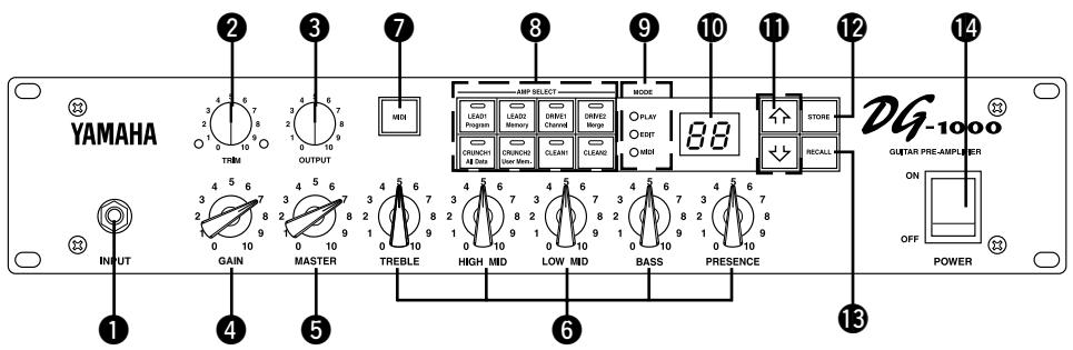
Front Panel
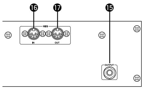
Rear Panel
Input Jack (INPUT)
Connect the guitar to this jack.
- Switch the power OFF before connecting the guitar.
Trim Control (TRIM)
Matches the guitar output level to the pre-amp's input level. ( pg. 4)
- TRIM level settings are not stored in memory.
Output Level Control (OUTPUT)
Controls the output level of the OUTPUT jack on the back panel. Matches the output level to the amp's input level. ( pg.4)
- Output level settings are not stored in memory.
4 Gain Volume (GAIN)
Controls the amount of distortion.
- No sound will be produced if GAIN is set to 0, even if the MASTER volume ⑤ is turned up.
Master Volume (MASTER)
Controls the overall volume of GAIN and tone controls settings.
Tone Controls
(TREBLE, HIGH MID, LOW MID, BASS, PRESENCE)
Controls the levels of their respective frequencies.
7 MIDI Button
Press this button to edit settings in the MIDI mode. ( pg. 6)
Amp Select Button/Amp Select Display (LEAD 1, 2/DRIVE 1,2/CRUNCH 1,2/CLEAN 1,2)
Selects one of the 8 preset amp types. The currently selected amp type is shown on the display. ( pg. 4)
Also acts as the MIDI function switch when in the MIDI mode. ( pg.6)
- When the amp select button is pressed, knobs 4 - 6 will return to their preset positions (GAIN & MASTER = 7, Tone Controls all = 5).
9 Mode Display Lamp (PLAY/EDIT/MIDI)
Displays the DG-1000's currently selected mode.
- PLAY (Play Mode):
Automatically enters this mode when a memory number is recalled, and when the power is switched on. ( pg. 4)
- EDIT (Edit mode)
Automatically enters this mode when tone control or amp select settings are changed. ( pg. 4)
- MIDI (MIDI Mode)
MIDI functions are edited in this mode.
Press the MIDl button 7 to enter the MIDl mode. ( pg.6)
10 Display
Displays Memory Numbers, Program Change Numbers, MIDI Channel, etc.
1 Buttons
Increases or decreases the memory number by 1. Also, increases or decreases values by 1, or switches the MIDI mode ON/OFF when in the MIDI mode. Values change continuously when the button is pressed and held.
STOREButton(STORE)
Press this button to save current sound settings to internal memory. ( pg. 5) Also, used to carry out bulk dump functions in the MIDI mode. ( pg. 6)
RECALL Button (RECALL)
Recalls settings from memory. Use the 1 / buttons to select a memory number (01 - 128), then press the RECALL button to recall those settings from memory. ( pg. 5)
14 POWER Switch (POWER)
The power switch for the DG-1000.
- Set the OUTPUT Volume ③ to 0 before turning the POWER ON/OFF.
15 OUTPUT Jack (OUTPUT)
Connect to the power amp (or guitar amp). ( pg. 4)
16 MIDI IN Jack
Connected to a MIDI Foot Controller's MIDI OUT jack, the DG-1000 can be controlled by an external foot controller. ( pg. 6)
MIDI OUT/THRU Jack
Connect to the MIDI IN jack of a device that can save MIDI data. Data stored in the DG-1000's memory can be saved to an external MIDI device (MIDI Data Filer, etc.). ( pg. 5)
Also, sends MIDI data, received by the MIDI IN jack 16, to an external device when MIDI Merge is set to ON. ( pg. 6)
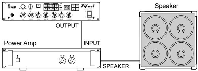
Connecting the DG-1000
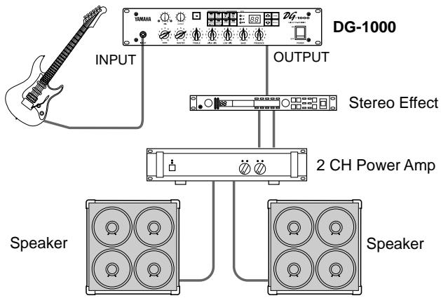
To set up a guitar amp system, connect the DG-1000 to a power amp and speaker.
As you know, power amps and speakers all have their own special characteristics. So the sound's character will change according to the type of devices used. The combined result of each device's character, room temperature, room humidity, and a variety of other factors, determines the guitar's sound. The purpose of the DG-1000 is to create sound by faithfully reproducing the dynamic range and tone nuance of the guitar as well as preserving the characteristics of the power amp, speakers, etc. The DG-1000 will surely provide you with the means to create your own personal sound.
Connecting Procedure
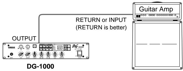
Make sure that the power is switched OFF on the DG-1000 and the power amp (guitar amp) before making any connections.
- Connect the OUTPUT jack on the rear panel of the DG-1000 to the INPUT jack on the power amp using a cable.
- Choose a cable that matches the required jack standard. The DG-1000's OUTPUT jack is monaural.
- Connect the power amp's speaker output (SPEAKER, etc.) to a speaker.
- Use a speaker that matches the power characteristics of the amp (power capacity, system impedance).
DG-1000
- Connecting the DG-1000 to a guitar amp is also possible
- Add a stereo effector to the system
How to use the DG-1000
Once the amp and speaker has been properly set up, try getting some sound out of the system.
■ First, acquire sound
- With the DG-1000 and power amp (guitar amp) power switched OFF, connect the guitar to the INPUT jack on the front panel.
- With the OUTPUT knob set to "0", switch the power ON.
- A short time after the power has been switched ON, the DG-1000's internal relay will produce a small "Click" sound. Once the sound is heard, set the power amp's (guitar amp's) volume to "0" and switch the power ON on the power amp (guitar amp).
- At first, set the DG-1000's TRIM and OUTPUT levels to "5" and strum the guitar. Then adjust the power amp's volume level.
- Once you have sound, set the TRIM and OUTPUT levels as described in the following procedures.
Set the TRIM level
The TRIM level is used to set the output level of the guitar to an optimum level for the DG-1000's INPUT jack. Depending on the TRIM level subtle picking nuances and the attack of a strong strum can be realized.
An improperly adjusted trim level will result in noise, feedback and a cut up sound.
- Output levels vary according to the type of guitar used. If a different guitar is used, adjust the trim level to match the guitar.
-
Even to create distortion, make sure that the TRIM level is properly adjusted, and use the GAIN control to create distortion.
-
Set the guitar's volume to its maximum level and strum it powerfully. Begin to adjust the TRIM level.
An optimum level is achieved when the Green LED is lit. - Continue adjusting the TRIM knob until the Red LED lights. Set the TRIM level to 10 if the Red LED does not light. If the Red LED lights, lower the TRIM level until the Green LED lights.
Set the OUTPUT level
Use the OUTPUT knob to set the DG-1000's required OUTPUT level.
Sound Setting
Choose one of the DG-1000's 8 preset amp types, then use the GAIN+MASTER, and Tone Controls to shape the sound.
- With one of the AMP SELECT buttons choose an amp type. The LED will light on the selected amp type button.
- Use the GAIN, MASTER, and the 5 Tone Controls to shape the sound.
- When an AMP SELECT button is pressed, all knobs (Except TRIM and GAIN) will return to their preset positions (GAIN & MASTER = 7, Tone Controls all = 5). To save edited settings, refer to "Store Settings" on the next page.
The DG-1000 has an internal memory that can hold up to 128 amp type and settings. Each memory can be recalled at any time. Motor drives in the knobs will automatically set them to the proper positions. Try storing a sound you created to memory.
Store Settings
-
Create a sound using the 8 preset amp types, GAIN, MASTER, and the 5 Tone Controls. The EDIT lamp lights on the MODE display.
-
If MODE display's MIDI lamp is lit, press the MIDl button so that the EDIT lamp lights.
-
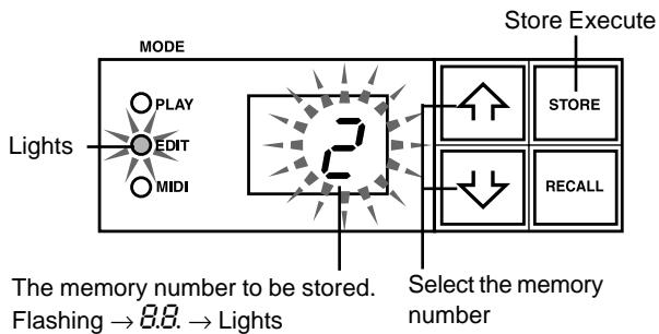
Use the / buttons to select the memory number to which the settings will be saved. The memory number will flash in the display.
-
Press and hold one of the 介 / 下 buttons to make memory numbers cycle rapidly.
- The third digit of the memory number (100 - 128) is represented by a dot between the two digits.
Sample) 128 is displayed as
- Hold the STORE button, for about one second, until "B.B." appears on the display.
Release the button, the flashing memory number will then light indicating the setting is saved to memory.
- TRIM and OUTPUT settings are not stored in memory. Use the MASTER knob to set backing and solo levels.
Data stored in memory (1 - 128) can be saved to an external MIDI storage device. Refer to the next page for details.
HINT Some hints on storing memory numbers
When storing memory, divide the memory numbers 1 - 128 into several groups.
Recalling memory from these groups is convenient. For example,
- Create groups according to the amp type (LEAD1, DRIVE 1, etc.).
For example, memory numbers 1-10 are LEAD 1 sounds.
- Create groups based on sound type (Distortion, Clean, etc.)
- Create groups based on live performance song lists.
- Create groups based on the type of guitar used (humbucker, etc.).
It's also a good idea to keep a chart listing what types of sounds are stored in memory numbers.
Recall Memory (Recall)
The settings stored in memory can easily be recalled by selecting a memory number.
- Check the Mode Display lamp.
If PLAY is lit:
Go to the next step.
If EDIT is lit:
The current settings are not stored in memory. If you want to save those settings, use the "Store Settings" procedure on the left page, then proceed to the next step.
If MIDI is lit:
Press the MIDl button to return to the PLAY or EDIT mode.
-
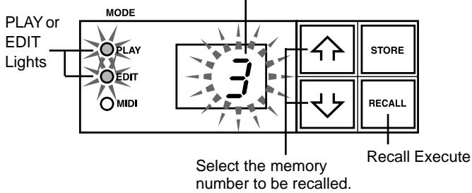
Use the / buttons to select the memory number to be recalled. The memory number appears on the display (flashing).
-
Press the RECALL button. The flashing memory number will then light. Each of the knobs, and the Amp Select Display will change according to the data recalled from memory.
-
Settings do not change until the RECALL button is pushed.
- TRIM and OUTPUT knob settings will not change with the Recall operation.
- It takes anywhere from 1 - 10 seconds for the knob settings to change however, internal settings (sound) will change instantly.
- “E i” will appear on the display if the volume knob does not go to its assigned position, or the device does not recognize the recall command after 20 seconds from the start of the RECALL operation.
Continued use of the device in this condition may result in fire or electrical shock. Take the unit to the music dealer where you purchased it, or to the nearest Yamaha Service Center for repair.
The memory number to be recalled goes from flashing display lit display
A MIDI foot controller or other external MIDI device can be used to select and recall memory. Refer to the following page for details.
Initialize the memory
Use the following operation to restore all of the internal memory (No. 1 - 128) to its original initialized condition (GAIN & MASTER = 7, All tone controls = 5). Anything that you have saved to memory will be lost so please use caution.
[Operation]
While holding both the MIDI button and the STORE button, switch the POWER ON.
What is MIDI?
MIDI is the abbreviation for: Musical Instruments Digital Interface. MIDI is a world standard communication interface that allows MIDI compatible musical instruments and computers to share musical information and control one another regardless of instrument type or maker. With the DG-1000, an external MIDI controller can be used to recall memory settings (program change), an external MIDI controller can be used to control the main volume (control change), and memory and MIDI settings can be exchanged with an external MIDI device (bulk dump).
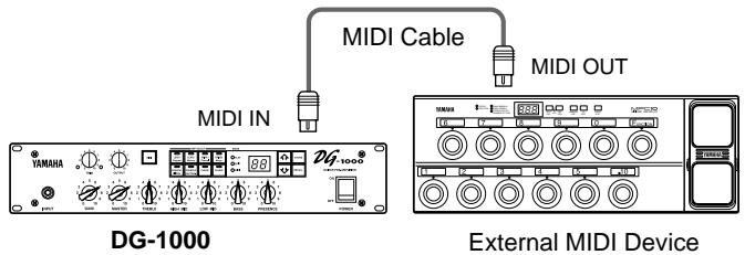
Using MIDI to Recall Memory
Program change messages from a Yamaha MIDI Foot Controller MFC10, etc., or external MIDI device can be used to recall settings in the DG-1000's memory.
1. Use a MIDI cable to connect the DG-1000's MIDI IN Jack to the MIDI OUT Jack on an external MIDI device.
- Use only a standard MIDI cable that is less than 15 meters in length. Using a longer cable may result in abnormal operation.
2. Set the DG-1000's MIDI receive channel and the external MIDI device's MIDI transmit channel to the same MIDI channel. (the factory preset is channel 1).
2-1. Press the MIDl button, the MIDl display lamp will light.
2-2. Press the DRIVE 1 button, the currently set MIDI receive channel is shown on the display.
2-3.Use the 合 / 山 buttons to select the MIDI receive channel (I - I ,RII, F) ^* is set to OMNI.
3. Create a program change table* (the factory preset is, Program Change No. = Memory No.).
- For example, "the received Program Change Number 1, recalls the DG-1000's Memory Number 5". To achieve this, assign the received program change number to the corresponding memory number.
3-1. With the Mode Display Lamp lit, press the LEAD 1 button.
3-2. Use the 介 / 山 buttons to select a program change number ( I - 2 ). The selected number appears on the display.
3-3. Press the LEAD2 button.
3-4. Use the 1 / 2 buttons to select the corresponding memory number ( I - c ). The number appears on the display.
3-5. If necessary, repeat steps 3-1 through 3-4.
4. When program memory data is transmitted from an external MIDI device, the corresponding memory assigned to the Program Change Table will be recalled.
About MIDI Control Changes
You can control the overall volume of the DG-1000 by connecting an external MIDI device's MIDI OUT jack to the DG-1000's MIDI IN jack, and transmit Number 7 Control Change Messages (Main Volume) to the DG-1000.
- With the exception of the Number 7 Control Change, the DG-1000 does not recognize any other MIDI Control Change messages.
- The Main Volume data will not change, even if a different memory number is selected.
-
When the POWER is switched ON, the Main Volume data is set to its MAX value.
-
After the Main Volume data is changed, and the external MIDI device is disconnected, the pre-amp's volume level may not be sufficient. If this case occurs, transmit a Control Change with a higher volume setting again, or switch the POWER OFF and then back ON.
Setting the MIDI Merge
To have data received by the DG-1000's MIDI IN jack, re-transmitted from the MIDI OUT jack, set the MIDI Merge to "a n". If not, set to "o F".
- Press the MIDI button, the MIDI Display will light.
- Press the DRIVE 2 button, the current MIDI Merge setting is shown in the display.
- Use the 介 / buttons to select "an/aF".
■ MIDI Bulk Out
The DG-1000's data can be sent to an external MIDI storage device (Yamaha MIDI Data Filmer MDF2, etc.) for data backup.
- Use a MIDI cable to connect the DG-1000's MIDI OUT Jack to the MIDI IN Jack on an external MIDI device.
- Press the MIDI button. The MIDI display lamp will light.
- To send data for the entire memory (128) + MIDI settings with the Bulk Out operation:
Press the CRUNCH1 button. "R / I" is shown in the display.
To send a single memory with the Bulk Out operation:
Press the CRUNCH2 button. Use the 介 / 介 buttons to select the memory number you wish to send.
4. Press the STORE button to transmit the memory data.
Press the MIDI button to cancel the operation.
- The device number is the same as the MIDI receive channel. If the MIDI receive channel is set to OMNI (R I I) or OFF (oF), the MIDI channel will be set to 1.
■ MIDI Bulk In
Use a MIDI cable to connect the DG-1000's MIDI IN Jack to the MIDI OUT Jack on an external MIDI device. Return DG-1000 backup data to the DG-1000.
- The MIDI bulk in operation is carried out in the PLAY or EDIT modes only. It can not be carried out in the MIDI mode.
- The device number is the same as the MIDI receive channel. If the MIDI receive channel is set to OMNI (R I I), the MIDI channel will be set to 1. It will not receive if it is set to OFF (a F).
- “L d” is shown on the display during the MIDI Bulk In operation.
■ Error Messages
If an error occurs during a MIDI operation, one of the following error message numbers will appear on the DG-1000's display.
_2 : MIDI receive buffer full.
Too much MIDI data is being received by the DG-1000 at one time. Try to reduce the amount of data being sent or, break the data into smaller blocks.
E3: Communication error.
An abnormality is detected in the transmitted data. Check all connections and relevant settings and try again.
^4 Bulk receive check sum error.
A check sum error has been detected in the MIDI bulk data received by the DG-1000. Check all connections and relevant settings and try again.
±b±bS : Bulk receive data abnormality.
An abnormality has been detected in the MIDI bulk data ro"eived by the DG-1000. Check all connections and relevant settings and try again.
Dimensions (L x H x P) 480 x 89 x 275 mm
Poids 6.0 kg
Volume de gain (GAIN)
Commande la grandeur de distorsion.
(TREBLE, HIGH MID, LOW MID, BASS, PRESENCE)