12big Rack Serial 2 - NAS LACIE - Free user manual and instructions
Find the device manual for free 12big Rack Serial 2 LACIE in PDF.

| Product Type | 12-bay Rackmount NAS |
| Brand | LaCie |
| Model | 12big Rack Serial 2 |
| Form Factor | Rackmount, 3U |
| Drive Bays | 12 x 3.5-inch SATA/SAS |
| Processor | Intel Xeon D or similar (varies by configuration) |
| Memory | Up to 128 GB DDR4 ECC (configurable) |
| Dimensions (W x D x H) | 482 x 710 x 132 mm (19 x 28 x 5.2 inches) |
| Weight | Approximately 18 kg (40 lbs) without drives |
| Power Supply | Dual redundant hot-swap 800W PSU |
| Power Consumption | Typical 250W, max 400W |
| RAID Support | Hardware RAID 0, 1, 5, 6, 10, 50, 60 |
| Network Interfaces | 4 x 10GbE (RJ45 or SFP+), optional 25GbE |
| Main Functions | File sharing, backup, virtualization, data protection, cloud tiering |
| Operating System | LaCie NAS OS (based on ZFS or ext4) |
| Cooling | 4 x hot-swappable fans (80mm) |
| Expansion | 1 x PCIe Gen3 slot for additional network or storage |
| Security | AES-256 encryption, secure erase, VPN server, firewall |
| Maintenance | Hot-swap drives and PSUs; front panel LCD for status |
| Spare Parts & Repairability | Field-replaceable units: drives, PSU, fans (not user-serviceable mainboard) |
| General Information | Designed for 24/7 operation in data centers, 3-year warranty |
Frequently Asked Questions - 12big Rack Serial 2 LACIE
User questions about 12big Rack Serial 2 LACIE
0 question about this device. Answer the ones you know or ask your own.
Ask a new question about this device
Download the instructions for your NAS in PDF format for free! Find your manual 12big Rack Serial 2 - LACIE and take your electronic device back in hand. On this page are published all the documents necessary for the use of your device. 12big Rack Serial 2 by LACIE.
USER MANUAL 12big Rack Serial 2 LACIE
natural_image
Exterior view of a black server rack with multiple orange rack-mounted units and a digital display (no visible text or symbols)1. INTRODUCTION
1.1. Safe Handling
- A LaCie 12big Rack Serial 2 enclosure can weigh up to 26kg (57lb). Do not try to lift it by yourself.
- Do not lift the enclosure by the handles on the PCMs. They are not designed to take the weight.
1.2. Safety
- All plug-in modules and blank plates are part of the fire enclosure and must only be removed when a replacement can be immediately added. The system must not be run without all modules or blanks in place.
■ Permanently unplug the unit before you move it or if you think it has become damaged in any way.
IMPORTANT: The enclosure MUST be grounded before applying power.
The enclosure must only be operated from a power supply input voltage range of 100-240 VAC.
- The plug on the power supply cord is used as the main disconnect device. Ensure that the socket outlets are located near the equipment and are easily accessible.
- When powered by multiple AC sources, disconnect all supply power for complete isolation.
In order to comply with applicable safety, emission and thermal requirements no covers should be removed and all bays must be populated with plug-in modules.
The power connection should always be disconnected prior to removal of a PCM from the enclosure.
- A safe electrical earth connection must be provided to the power supply cords. Check the grounding of the enclosure before applying power.
- Provide a suitable power source with electrical overload protection to meet the requirements laid down in the technical specification.
- When bifurcated power cords ('Y' leads) are used, they must only be connected to a supply range of 200-240 V.
- A faulty PCM must be replaced with a fully operational module within 24 hrs.
- Do not remove a faulty PCM unless you have a replacement model of the correct type ready for insertion.
CAUTION: If this equipment is used in a manner not specified by LaCie, the protection provided by the equipment may be impaired.
CAUTION: The optional RJ45 socket on the I/O module, it is for Ethernet connection only and must not be connected to a telecommunications network.
1.3. Rack System Precautions
The following safety requirements must be considered when the unit is mounted in a rack.
- The rack construction must be capable of supporting the total weight of the installed enclosure(s) and the design should incorporate stabilizing features suitable to prevent the rack from tipping or being pushed over during installation or in normal use.
- When loading a rack with the units, fill the rack from the bottom up and empty from the top down.
■ To avoid danger of the rack toppling over, do not slide more than one enclosure out of the rack at a time. - The system must be operated with low pressure rear exhaust installation [back pressure created by rack doors and obstacles not to exceed 5 pascals (0.5mm water gauge)].
The rack design should take into consideration the maximum operating ambient temperature for the unit, which is 40^ C. - The rack should have a safe electrical distribution system. It must provide over-current protection for the unit and must not be overloaded by the total number of units installed in the rack. When addressing these concerns consideration should be given to the electrical power consumption rating shown on the nameplate.
- The electrical distribution system must provide a reliable earth for each unit in the rack.
- Each power supply in each unit has an earth leakage current of 1.0mA. The design of the electrical distribution system must take into consideration the total earth leakage current from all the power supplies in all the units. The rack may require labelling with "HIGH LEAKAGE CURRENT. Earth connection essential before connecting supply".
The rack when configured with the units must meet the safety requirements of UL 60950-1 and IEC 60950-1.
1.4. PCM Operation
IMPORTANT: Do not remove covers from the PCM. Danger of electric shock inside. Return the PCM to your supplier for repair.
IMPORTANT: Do not remove a PCM unless a replacement can be immediately added. The system must not be run without all units or module blanks in place.
1.5. ESD Precautions
It is recommended that you fit and check a suitable anti-static wrist or ankle strap and observe all conventional ESD precautions when handling plug-in modules and components. Avoid contact with backplane components and module connectors, etc.
2. PREPARATION
2.1. Before You Begin
Before you begin, make sure the site where you intend to set up and use your storage system has the following:
- Standard power from an independent source or a rack power distribution unit with a UPS.
- Host computer with the correct firmware, BIOS and drivers. Contact your supplier for the correct software levels.
Before setting up your enclosure ensure you have the following:
■ SAS HBA
■ Mini-SAS to Host Cable
Power Cord
■ Rack kit (if installing within a rack)
Refer to your supplier for a list of qualified accessories for use with the enclosure. The Accessory Box contains the power cords and other ordered accessories.
2.2. Unpacking the Storage System
-
Inspect the packaging for crushes, cuts, water damage or any other evidence of mishandling during transit. If any damage appears present, for future reference photograph the packaging before opening.
-
Unpack the system. See Figure 1.
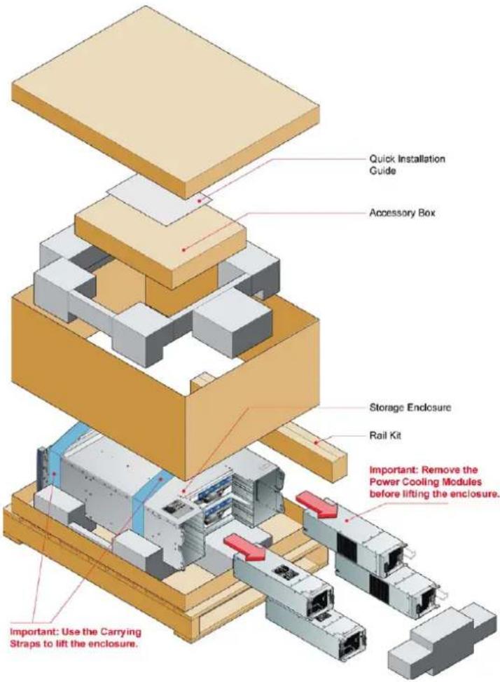
text_image
Quick Installation Guide Accessory Box Storage Endlosure Rail Kit Important: Remove the Power Cooling Modules before lifting the enclosure. Important: Use the Carrying Straps to lift the enclosure.Figure 1 - Unpacking the Storage System
3. INSTALLATION
3.1. Mounting the System into a Rack
- Remove the Rack Mounting Rail Kit from the Accessory Box and check for damage.
- Attach left and right chassis slides to the enclosure sides using 8 M3 x 4 buttonhead screws (see Figure 2).
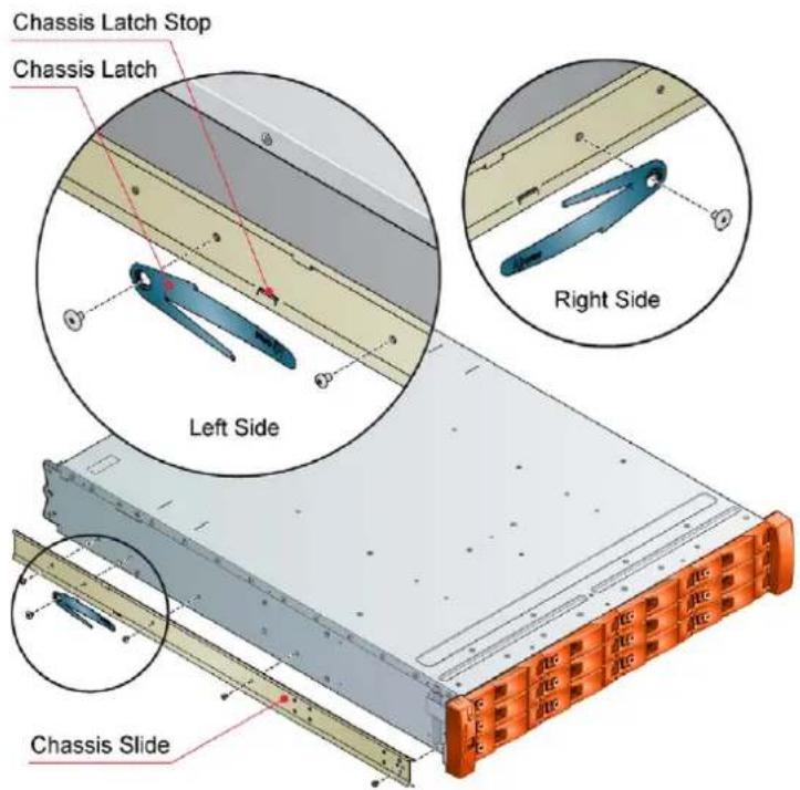
text_image
Chassis Latch Stop Chassis Latch Left Side Right Side Chassis SlideFigure 2 - Securing Chassis Slides to Enclosure

text_image
Square Hole Front Rack Post Rack Bracket ASM Round Hole Front Rack Post Clamping Screws Rear Rack Post Slide Screw (x4) Slide Washer (x4) Remove this nut if installing into tapped hole rack Tapped Hole Front Rack PostFigure 3 - Securing Brackets to Rack
- Assemble the left and right chassis latches using the special chassis latch screws. Ensure the latch is orientated as shown in Figure 2, with the spring arm located against its stop. On the right hand side this is at the top, on the left at the bottom.
- Assemble the rack brackets to the rack posts as follows (see Figure 3):
a. Position the location pin at the rear of the rail into a rear rack post hole. Attach the bracket to the rear rack post using the washers and screws supplied. The screws should be left loose.
b. Extend rail to fit between the front and rear rack posts.
c. Attach the bracket to the front rack post using the washers and screws supplied. The screws should be left loose.
d. Tighten the two clamping screws located along the inside of the rear section of the rack bracket (see Figure 3).
- Mount the enclosure into the rack as follows (see Figure 4):
a. Lift the enclosure and align it with the rack rails.
b. Carefully insert the chassis slides into the rack rails and push fully home.
c. Tighten the rear rack bracket mounting screws.
d. Withdraw enclosure until it reaches the hard stops (approx. 400mm) and tighten the front rack bracket mounting screws.
e. Return the enclosure to the fully home position.

natural_image
3D rendering of a server rack unit with orange rack-mounted components and mounting bracket (no visible text or symbols)Figure 4 - Mounting the System into a Rack
3.2. Connecting to Host
CAUTION:
- When using this product as an expansion chassis, software update may automatically occur. Please wait for several minutes for the update and then reboot of the system.
- When using this product as an expansion chassis for the LaCie 12big Rack Network, software should be updated using the appropriate method mentioned in the LaCie 12big Rack Serial 2 User Manual.
IMPORTANT: Connections can be made up to a max. of 4 enclosures.
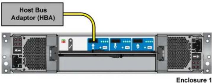
text_image
Host Bus Adaptor (HBA) Enclosure 1Figure 5 - Single Host - Single Enclosure

flowchart
graph TD
    A["Host Bus Adaptor (HBA)"] --> B["Server Rack 1"]
    C["Host Bus Adaptor (HBA)"] --> D["Server Rack 2"]
    E["Host Bus Adaptor (HBA)"] --> F["Server Rack 3"]
    G["Host Bus Adaptor (HBA)"] --> H["Server Rack 4"]
    style A fill:#f9f,stroke:#333
    style C fill:#f9f,stroke:#333
    style E fill:#f9f,stroke:#333
    style G fill:#f9f,stroke:#333
    style B fill:#ccf,stroke:#333
    style D fill:#ccf,stroke:#333
    style F fill:#ccf,stroke:#333
    style H fill:#ccf,stroke:#333
Figure 6 - Dual Host - Multiple Enclosures
3.3. Power On
Power on the storage system by connecting the power cables to the power distribution unit (PDU), powering on the PDU, moving the PCM switches to the ON position, and then powering on the host system.
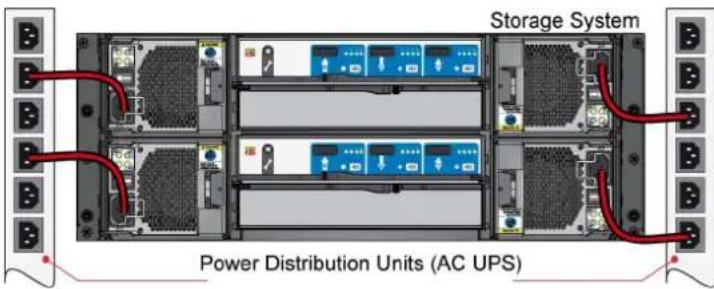
text_image
Storage System Power Distribution Units (AC UPS)Figure 7 - Connecting the AC Power Cables to the PDU
4. LED STATES
4.1. I/O Module LED States

text_image
Factory Use Only Connectors I/O Module & Fault LEDs PHY Connection LEDsFigure 8 - I/O Module LEDs
| Status I/O Module Fault | (Amber) | I/O Module OK (Green) | Host Port Activity (Green) |
| I/O Module OK Off On X | |||
| I/O Module Fault On Off X | |||
| No Host Port Connection X X Off | |||
| Host Port Connection - No Activity X X Off | |||
| Host Port Connection Activity X X Flashing | |||
| I/O Module VPD Error X Flashing X |
X = Disregard
4.2. PCM LED States
| Status PCM OK | (Green) | Fan Fail (Amber) | AC Fail (Am- ber) | DC Fail (Am- ber) |
| No AC power (any PCM) Off Off Off Off | ||||
| No AC power (this PCM only) Off Off On On | ||||
| AC present PCM On OK On Off Off Off | ||||
| PCM fan fail Off On Off Off | ||||
| PCM fault (over temp., over voltage, over current) | Off On On On | |||
| Standby mode Flashing Off Off Off | ||||
| PCM firmware download Off Flashing Flashing Flashing |
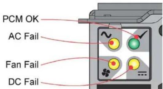
text_image
PCM OK AC Fail Fan Fail DC FailFigure 9 - PCM LEDs
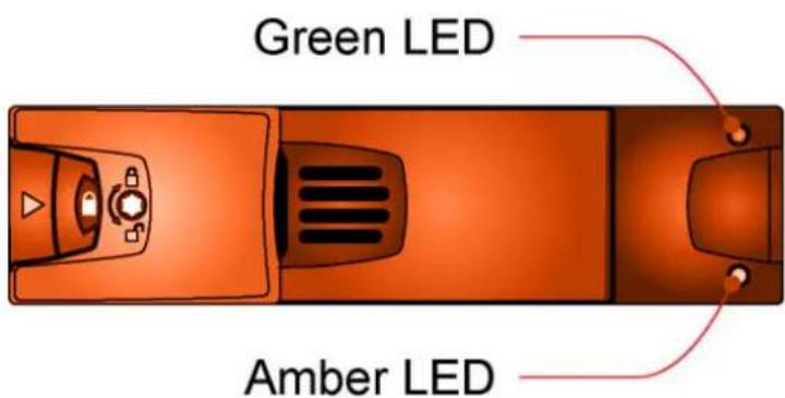
text_image
Green LED Amber LEDFigure 10 - Drive LEDs
4.3. Drive LED States
| Status Green LED Amber LED Associated Ops | Panel LED | ||
| No drive installed Off Off None | |||
| Drive installed and operational On/Blink with acitivity or startup | X None | ||
| SES device identity set On Flash 1s on / 1s off None | |||
| SES device fault bit set On On Logical fault (Amber) | |||
| Power control circuit failure Off On Module fault (Amber) | |||
| Failed disk array On Flash 3s on / 1s off Logical fault (Amber) |
X = Disregard
4.4. Front Panel LED States
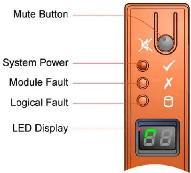
text_image
Mute Button System Power Module Fault Logical Fault LED DisplayFigure 11 - Front Panel LEDs
| Front Panel LEDs | |||||
| System Power (green/amber) | Module Fault (Am-ber) | Logical Fault (Am-ber) | LED Diplay A | Associated LEDs/Alarms | Status |
| On Off Off X Aux present, overall power | failed or switched off | ||||
| On On XX Single beep, | then double beep | Ops panel Power On (5s) test state | |||
| On Off Off X Power On, all functions good | |||||
| On On XX PCM fault | LEDs, fan fault LEDs | Any PCM fault, fan fault, over or under temp. | |||
| On On XX SBB module | LEDs | Any SBB module fault | |||
| On On XX Enclosure logical fault | |||||
| On Flash XX Module sta- | tus LED on SBB module | Unknown (invalid or mixed)SBB module type installed, I2C bus failure (inter SBB comms)EBOD VPD configuration error | |||
| On Flash XX PCM fault | LEDs, fan fault LEDs | Unknown (invalid or mixed)PCM type installed, or I2C bus failure (PCM comms) | |||
| On X On X Array in | failed or degraded state | Drive failure has occurred causing loss of availability or redundancy | |||
| On X Flash X Arrays in | impacted state | Arrays operating background function | |||
| On Flash Flash X SES State S1 Enclosure ID setting different | from Start of Day | ||||
| XX Flash SES controlled enclosure ID | |||||
X = Disregard
Contact Us
LaCie Asia
25/F Winsan Tower
98 Thomson Road
Wanchai, Hong-Kong, China
info.asia@lacie.com
LaCie Australia
458 Gardeners Road
Alexandria, NSW 2015
info.au@lacie.com
LaCie Benelux
Vorstlaan / 165 Bld du Souverain
B-1160 Brussels, Belgium
info.benelux@lacie.com
LaCie Canada
235 Dufferin St.
Toronto, Ontario M6K 1Z5
info.ca@lacie.com
LaCie France
17, rue Ampère
91349 Massy Cedex
info.fr@lacie.com
LaCie Germany
Am Kesselhaus 5
D-79576 Weil Am Rhein
info.de@lacie.com
LaCie Italy
Milano Business Park
Edificio B1
(Sweden, Denmark, Norway, Finland)
Sveavägen 90, 5tr
113 59 Stockholm, Sweden
info.nordic@lacie.com
LaCie Spain
LaCie United Kingdom and Ireland
LaCie Ltd, Power Road Studios
114 Power Road
Chiswick, London, UK W4 5PY
UK: info.uk@lacie.com
Ireland: info.ie@lacie.com
LaCie USA
22985 NW Evergreen Pkwy
Hillsboro, OR 97124
sales@lacie.com
LaCie Worldwide Export
17, rue Ampère
91349 Massy Cedex, France
sales.intl@lacie.com
support.intl@lacie.com