CV80DC - Vacuum Cleaner HITACHI - Free user manual and instructions
Find the device manual for free CV80DC HITACHI in PDF.

User questions about CV80DC HITACHI
0 question about this device. Answer the ones you know or ask your own.
Ask a new question about this device
Download the instructions for your Vacuum Cleaner in PDF format for free! Find your manual CV80DC - HITACHI and take your electronic device back in hand. On this page are published all the documents necessary for the use of your device. CV80DC by HITACHI.
USER MANUAL CV80DC HITACHI
natural_image
Line drawing of a vacuum cleaner with handle and control panel (no text or symbols)CV80DP

natural_image
Line drawing of a vacuum cleaner with handle and ventilation slots (no text or symbols)CV80DC/D
PART IDENTIFICATION

text_image
Handle Dust bag full indicator Power control knob (except CV-80D) Bag compartment clamp Front cover Furniture guard ON-OFF switch Bag compartment lid Duct hose Cured joint pipe Dusting brush Curved joint pipe Cord strage hooks Flexible hose Carrying handle Extension pipes Crevice nozzle Hose strage hook & cord strage hook Handle release pedal (3 positions)Fig. 1
HOW TO OPERATE
TO INSTALL THE HANDLE
- Open the bag compartment lid by pulling the bag compartment clamp.
- Insert the handle into the opening on the top of the cleaner and
tighten screw ②

text_image
Technical diagram of a hair dryer with labeled parts, showing a hand holding a screwdriver to adjust the component.Fig. 2
ON-OFF SWITCH
Turn cleaner on or off by pushing downward on the power switch ③.
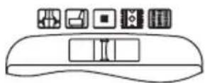
VARIABLE POWER CONTROL (except CV-80D, Fig.4)
The HITACHI vacuum cleaner CV-80DP/DC has an electronic power control. The suction power and the rotary brush speed can be regulated to suit the floor covering by sliding the control knob ④If a stronger suction is required for thick carpets and hard floors etc., simply slide the knob ④to the right side marked 📁. Likewise, the suction can be reduced for fabrics and curtains etc., adjusting the knob to the left side marked 📁. mark is for the economical middle power position.
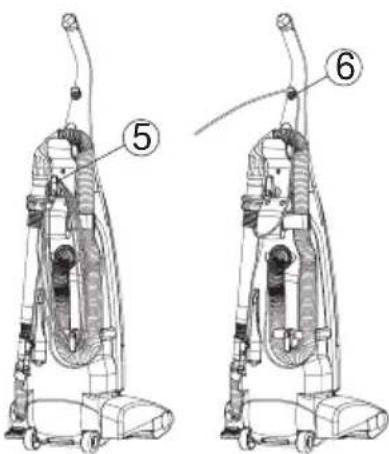
CORD STORAGE AND RELEASE
- To store the cord, turn the upper cord storage hook ⑤ to the upward position, and wrap the cord around the hooks.
- To release the power cord, turn the upper cord storage hook down ward, then pull off the complete cord.
- To help secure the cord during use, fix it on the upper cord storage hook ⑥
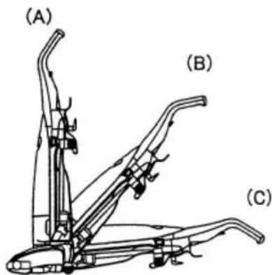
HANDLE POSITION
To change the position of the handle, first press with foot on the handle release pedal at the rear of the cleaner, and then lower the handle.
(A) Upright position: When the handle is in this position the rotary brush is automatically raised away from the floor.
(B) Normal working position: This position allows you to raise the front of the nozzle head to clear steps.
(C) Low position: For reaching under low furniture.
NOTE: The handle should always be in upright position when cleaning tools are used.

natural_image
Line drawing of a mechanical device with a curved handle and labeled part (3), no text or symbols present.Fig. 3

text_image
Diagram of a refrigerator interior with labeled buttons and panel indicatorsFig. 4
text_image
Technical diagram of a vacuum cleaner with labeled parts 5 and 6Fig. 5
text_image
(A) (B) (C)Fig. 6
AUTOMATIC HEIGHT CONTROL
The HITACHI vacuum cleaner has an automatic height control, which adjusts the nozzle to the proper height of any carpet pile.

natural_image
Technical line drawing of a mechanical assembly, possibly a vehicle or robotic arm, with no visible text or symbols.
natural_image
Technical line drawing of a mechanical assembly with no visible text or symbolsDUST BAG FULL INDICATOR
When the orange sign appears in the window continuously, change the dust bag.
Never allow the bag to become so full that the dirt may choke the passages to the bag.
Change the bag frequently when using the cleaner on new carpets, due to rapid accumulation of carpet fluff. In case the orange sign is still visible after changing the bag, turn the cleaner off, unplug the cord and check whether the duct hose is clogged. If so remove blockages.
NOTE: If the cleaner is used when the orange sign appears in the window, it will not draw enough air and the motor may overheat and may eventually burn out.
CARRYING HANDLE
To move your cleaner from room to room, carry it by the carrying handle @n the back of the cleaner or roll it on the rear wheels.
EDGE CLEANING
Brushed edge cleaning is provided on the both sides of the cleaner to remove imbedded dirt in carpet close to the skirting board or wall.
Guide each side of the cleaner parallel to the wall or furniture.
FRONT EDGE CLEANING
The front edge cleaning is a special head function that provides good performance at the corner and wall edges of a room.

text_image
⑧Fig. 8

text_image
9 Rear wheels Edge cleaningFig. 9

text_image
Flap Flap opens at cornerFig. 10
HOW TO USE TOOLS
Use the tools you require for cleaning hard floors, fabrics and curtains etc.
- Ensure the cleaner is in the upright position.
-
Hold the dusting brush and the extension pipe as shown in Fig.11, and disconnect the dusting burash from the extension pipe.
-
Turn the hose strage hook counter clockwise, and remove the flexible hose from the back of the cleaner.
-
When use the extension pipes, remove them from the back of the cleaner. The extension pipe assembly consists of two pipes-with one located inside the eter for storage.
-
The tools can be connected as shown in Fig.13.
NOTE: After having finished using the tools, re-insert the tools and restore the flexible hose on body.
NOTE: The extension pipes should be re-inserted as shown in Fig.11.
NOTE: Rotary brush is not disconnected when tools are in use and care should be taken not to run over the mains lead.

text_image
Technical diagram of a vacuum cleaner with numbered parts and an upward arrow indicating motion or assembly.Fig. 11

text_image
Using the dusting brush
text_image
Using the crevice nozzle
text_image
Using the fabric nozzleFig. 12
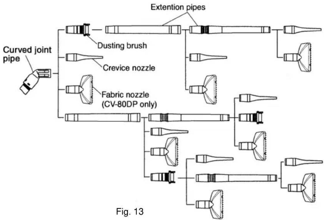
flowchart
graph TD
    A["Curved joint pipe"] --> B["Dusting brush"]
    A --> C["Crevice nozzle"]
    A --> D["Fabric nozzle (CV-80DP only)"]
    B --> E["Extension pipes"]
    C --> E
    D --> E
    style A fill:#f9f,stroke:#333
    style E fill:#ccf,stroke:#333
    note right of E
        Fig. 13
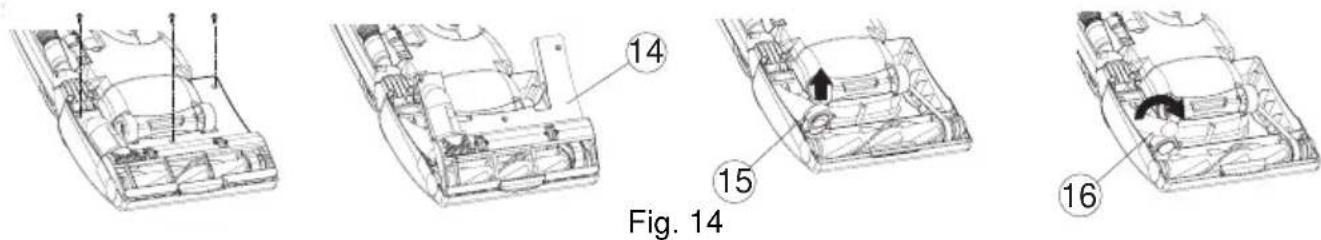
HOW TO CLEAR A BLOCKAGE
If your cleaner is used when the dust bag is full or any blockages are sucked in by accident, the air ducts may become clogged. If this occurs, remove the blockages or obstructions from the air ducts as follows.
CAUTION: Be sure to disconnect the plug from the electrical outlet.
\* DUCT HOSE
- Change the dust bag. (See page 6)
- Turn the cleaner over. Release the handle to the middle position. Remove the 3 screws from the belt cover ⑭
- Remove the belt cover, and take off the hose supporter ⑮ check the duct hose ⑯.
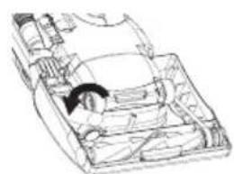
- To remove the duct hose, twist it clockwise.
-
After removing blockage from the duct hose, reinstall the duct hose by twisting counterclockwise, and replace the hose supporter on the case securely.
-
Place the four projections of the belt cover to the windows provided on the front end of case and replace the belt cover, and re-fasten the screws securely.
natural_image
Line drawing of a car interior with visible structural components (no text or symbols)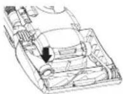
natural_image
Technical line drawing of a mechanical component with an arrow indicating a specific part (no text or symbols present)Fig. 15
natural_image
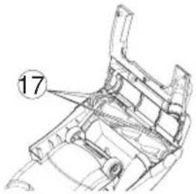
Technical line drawing of a mechanical component with numbered annotation (17), no readable text or symbols present.\* FLEXIBLE HOSE
- To disconnect flexible hose from the suction inlet, press two joints firmly.
- After removing blockage from the flexible hose and/or suction inlet, replace the hose and connect securely.
\* JOINT PIPE
Blockages may be cleared by separating the curved joint pipe from the hose. To separate the joint pipe, depress the two claws which are located in the holes on both sides of joint pipe and pull apart.
To re-connect push hose back into joint pipe and twist until two claws ①ocate with holes . ②

text_image
Technical diagram of a garment sleeve with numbered component labelFig. 16

text_image
19 21 20Fig. 17
HOW TO EXCHANGE THE DUST BAG
\* TAKING OUT THE DUST BAG
- Remove the plug from the electrical outlet.
Open the bag compartment lid by pulling the bag compartment clamp as shown in Fig18.
- To remove the dust bag ⑧ supported by the bag holder, push down the top end ⑳ of the bag holder, then pull it out carefully.

natural_image
Line drawing of a vacuum cleaner with handle and base (no text or symbols)Fig. 18 Fig. 19
text_image
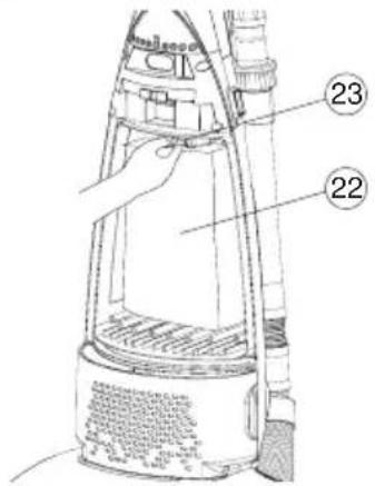
Technical diagram of a vacuum cleaner with labeled parts 22 and 23, showing internal components and wiring.\* FITTING THE NEW DUST BAG
- Insert the bottom of the cardboard collar ⑳ into the collar support ⑲ of the dust receptacle, and push the top edge until it catches behind the lug ⑳ of the bag holder.
- To replace the bag compartment lid, first insert the projection of the lid into the groove on the cleaner and push into place.
- Make sure you always have available spare paper bags.
The HITACHI PAPER BAG has been made especially for your cleaner. Paper bags may be purchased from your local dealer or from a HITACHI service center. In the event that replacement bags(or drive belts) are not available at your local shops, for where to buy please contact 01628 643000.
NOTE: To avoid using the cleaner without the paper bag, the clamp system of your cleaner prevents the bag compartment lid from being clamped when the paper bag has not been replaced, or has not been set properly in place.
NOTE: Put the bottom end of the paper bag into the bottom of the bag compartment so that the bottom end of the paper bag could not be caught between the bag compartment lid and the cleaner.
text_image
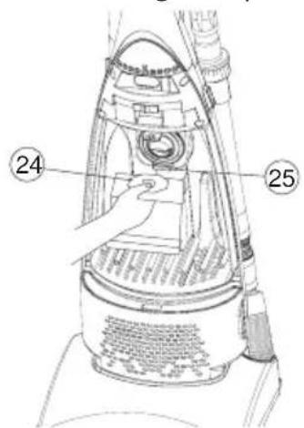
Technical diagram of a vacuum cleaner with labeled parts 24 and 25, showing internal components and wiring.
text_image
26 24 25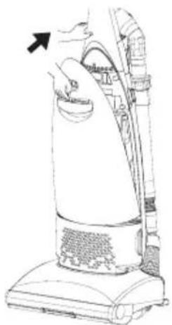
natural_image
Line drawing of a vacuum cleaner with an arrow indicating the handle (no text or symbols present)Fig. 20 Fig. 21 Fig. 22
CARE OF AIR FILTERS
\* MOTOR PROTECTION AIR FILTER(Fig. 22)
Once or twice a year, or when it becomes visibly soiled, the motor protection air filter ② may need cleaning.
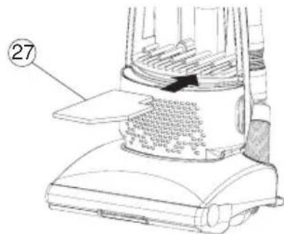
- Remove the filter from the bottom of the bag compartment as shown in Fig. 23 and wash in warm water.
- After washing the filter, dry thoroughly away from direct sun-light and fit it back into the cleaner.
NOTE: If the air filter is used when wet, suction is impaired and the motor may be damaged.
\* AIR FILTER (for CV-80D)
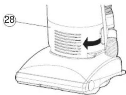
HYGIENIC AIR FILTER (for CV-80DC)(Fig. 24,25)
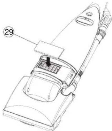
Your vacuum cleaner has a highly efficient electrostatic exhaust air filter ⑲ to trap even the finest dust particles in the exhaust air.
Once or twice a year, when the filter gets dirty, change the filter as follows.
- Open the front cover ⑳.
- Remove the old filter from the cleaner.
- Fit a new filter in th cleaner.
Hygienic air filters may be purchased from your local dealer.
In the event that replacement filters are not available at your local shops, for where to buy please contact 01628 643000.
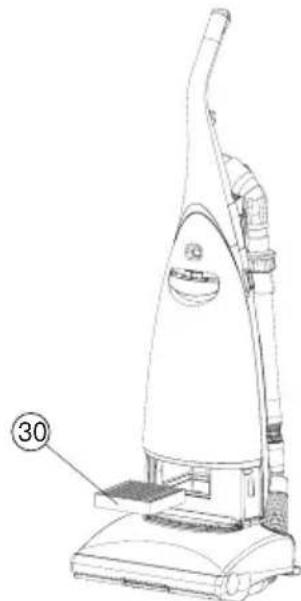
\* HEPA CLEAN FILTER (for CV-80DP)(Fig. 24,26)
Your vacuum cleaner has a highly efficient electrostatic exhaust air filter ③0 to trap even the finest dust particles in the exhaust air.
Once or twice a year, when the filter gets dirty, change the filter as follows.
- Open the front cover ⑳.
- Remove the old filter from the cleaner.
- Fit a new filter in the cleaner.
HEPA CLEAN filters may be purchased from your local dealer.
In the event that replacement filters are not available at your local shops, for where to buy please contact 01628 643000.
text_image
27Fig. 23
text_image
28Fig. 24
natural_image
Line drawing of a vacuum cleaner with labeled part (29), no text or symbols presentFig. 25
natural_image
Line drawing of a vacuum cleaner with labeled part (30), no text or symbols presentFig. 26
SERVICING AND REPAIRS
CAUTION: Be sure to disconnect the plug from the electrical outlet before replacing the belt or the rotary brush.
\*HOW TO REPLACE THE BELT
The drive belt should be checked regularly to be sure it is in good condition. If it is stretched, cracked or cut, it should be replaced.
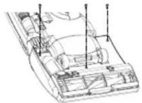
- Turn the cleaner over. Release the handle to the middle position.
Remove the 3 screws from the belt cover.(Fig. 27)
-
Remove the belt cover ④as shown.
-
Lift the rotary brush assembly out of the brush housing and remove the worn or broken belt ③2
natural_image
Technical line drawing of a vehicle chassis with structural components and mounting points (no text or labels)
natural_image
Technical line drawing of a mechanical assembly with numbered component (14), no readable text or symbols present.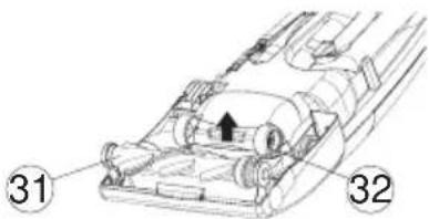
text_image
Technical diagram of a vehicle interior with numbered components and directional arrow indicating motion or movement.Fig. 27
- Place one end of the new belt over the motor shaft, and then slip the other end around the pulley of the rotary brush. Reinstall the rotary brush back into position.
Press firmly both sides of the rotary brush to be sure they are securely in place.
- Place the four projections of the belt cover to the windows provided on the front end of the case and replace the belt cover, and re-fasten the screws securely.

natural_image
Technical diagram of a mechanical assembly with numbered component (32), no readable text or symbols present
natural_image
Technical line drawing of a vehicle chassis with internal components and a directional arrow (no text or symbols)
text_image
17Fig. 28
\* HOW TO REPLACE THE ROTARY BRUSH
Be sure to disconnect plug from the electrical outlet. Remove the belt cover, the belt, and the rotary brush assembly following the direction previously given.
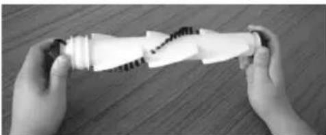
- Grasp the rubber end caps and turn them counterclockwise until one of the end caps comes off as shown in Fig. 29.
- Separate the rotary brush from other parts.
- Reassemble each part with new rotary brush as shown in Fig. 30. Be careful
not to forget to install any parts.
- Screw on the end caps and tighten.
- Replace the belt, the rotary brush and the belt cover as described previously.
natural_image
Two hands holding a white plastic object with a zigzag seam, placed on a wooden surface (no text or symbols visible)Fig. 29

text_image
Bearing case Ball bearing End cap Thrust washer Shaft Shaft Ball bearing Rotary brush Bearing case Ball bearing End cap Thrust washerFig. 30
HOW TO MAINTAIN CLEANING EFFICIENCY
- The plug of the power supply cord should be removed from the socket outlet before cleaning the appliance or undertaking maintenance operations.
- The supply cord on this appliance can only be replaced by the use of special tools and if it is damaged the appliance must be returned to the manufacturer or an accredited service agent for repair.
● Change the dust bag before it is excessively filled. - If the rotary brush becomes jammed by picking up large solid objects, bulky matter or the like, take it out after unpluging the cord. Remove any threads and long strings entwined round the rotary brush after cutting through.
- Only Hitachi special composition carbon brushes must be used in this cleaner. Replacement of the brushes must be carried out by an Hitachi dealer/service center.
- To clean the cleaner body and attachments, wipe with a soapsuds-soaked cloth. Avoid using alcoholic content liquids.
TO AVOID ACCIDENTS
● Always disconnect cord from electrical outlet before servicing the cleaner.
- Be sure to replace a new paper bag after disposing of the full one. There is a device which prevents the bag compartment lid from being closed when the paper bag has not been replaced. Do not tamper with this to use without bags as dust will be sucked directly into the mechanical parts and may damage the motor.
- Keep fingers, hands, feet and hair away from revolving rotary brush.
- Do not pick up matches, fireplace ashes or smoking material with the vacuum cleaner as a possible fire hazard may result.
- Avoid picking up sharp objects. They may damage the vacuum cleaner and the bag.
- Do not use the clener to pick up wet dirt, and avoid using it in a wet and moist place as moisture may damage the motor and other mechanical parts.
- Do not block the air flow. Any blockages or obstructions to the nozzle, hose, etc. or the exhaust air outlet can cause loss of power and motor overheating.
- Do not run the cleaner over cord. It may damage insulation.
- Avoid cleaning the switch and receptacle parts with wet cloth and splashing water on it as moisture may cause a short circuit.
- Your vacuum cleaner is not a toy. Do not allow children to play with it. Do not leave the vacuum cleaner connected to an electrical outlet unattended.
● Warning: Electric shock could occur if used outdoors or on wet surfaces.
- Warning: During use of the (accessory) tools, the rotary brush will continue to rotate and care must be taken to keep hands and the mains lead clear of the underside of the vacuum cleaner.
- Warning: When using accessory tools, the rotary brush will continue to rotate, so care must be taken not to leave the vacuum cleaner standing on an uneven surface, e.g. stairs, as this may result in damage to a carpet or other surface.
- Warning: Do not leave the vacuum cleaner running continuously on one part of a floor surface, e.g. when answering the phone, as this may result in damage. Switch off the vacuum cleaner.
IMPORTANT
The main slead on this equipment is supplied with a moulded plug incorporating a fuse, the value of which is indicated on the pin face of the plug. Shoud the fuse need to be replaced, an ASTA or BSI approved BS 1362 fuse must be used of the same rating. If the fuse cover is detachable never use the plug with the cover omitted. If a replacement fuse cover is required, ensure it is of the same colour as that visible on the pin face of the plug. Fuse covers are available from your dealer.
DO NOT cut off the mains plug from this equipment. If the plug fitted is not suitable for the power points in your home or the cable is too short to reach a power point, then obtain an appropriate safety approved extension lead or consult your dealer.
Should it be necessary to change the mains plugs, this must be carried out by a competent person, preferably a qualified electrician.
If there is no alternative to cutting off the mains plug, ensure that you dispose of it immediately, having first removed the fuse, to avoid a possible shock hazard by inadvertent connection to the mains supply. IMPORTANT
The wires in the mains lead are coloured in accordance with the following code:
Blue=Neutral, Brown=Live
As these colours may not correspond with the coloured markings identifying the terminals in your plug, proceed as follows:
The wire coloured BLUE must be connected to the terminal marked with the letter N or coloured BLUE or BLACK. The wire coloured BROWN must be connected to the terminal marked with the letter L or coloured BROWN or RED.
On no account connect either of these wires to the terminal marked E or by the earth symbol or coloured green or green and yellow.
THIS PRODUCT CONFORMS WITH THE PROTECTION REQUIREMENTS OF COUNCIL DIRECTIVES 89/336/EEC, 92/31/EEC, AND 93/68/EEC RELATING TO ELECTROMAGNETIC COMPATIBILITY.
HITACHI
Hitachi, Ltd. Tokyo, Japan
International Sales Division
THE HITACHI ATAGO BUILDING,
No. 15–12 Nishi Shinbashi, 2 – Chome,
Minato - Ku, Tokyo 105-8430, Japan.
Tel: 03 35022111
HITACHI EUROPE LTD,
Whitebrook Park
Lower Cookham Road
Maidenhead
Berkshire
SL6 8YA
UNITED KINGDOM
Tel: 01628 643000
Fax: 01628 643400
Email: consumer-service@hitachi-eu.com
HITACHI EUROPE S.A.
364 Kifissias Ave. & 1, Delfon Str.
152 33 Chalandri
Athens
GREECE
Tel: 1-6837200
Fax: 1-6835964
Email: service.hellas@hitachi-eu.com
HITACHI EUROPE GmbH
Munich Office
Dornacher Strasse 3
Email: HSE-DUS.service@hitachi-eu.com
HITACHI EUROPE S.A.
Gran Via Carlos III, 101-1
08028 Barcelona
SPAIN
Tel: 93 409 2550
Fax: 93 491 3513
Email: customerservice.italy@hitachi-eu.com
HITACHI Europe AB
Box 77 S-164 94 Kista
SWEDEN
Tel: +46 (0) 8 562 711 00
Fax: +46 (0) 8 562 711 13
Email: csgswe@hitachi-eu.com
HITACHI EUROPE S.A.S
Lyon Office
B.P. 45, 69671 BRON CEDEX
FRANCE
Tel: 04 72 14 29 70
Fax: 04 72 14 29 99
HITACHI EUROPE LTD (Norway) AB
STRANDVEIEN 18
1366 Lysaker
NORWAY
Tel: 67 5190 30
Fax: 67 5190 32
Email: csgnor@hitachi-eu.com
HITACH EUROPE AB
Egebækgård
Egebækvej 98
DK-2850 Nærum
DENMARK
Tel: +45 43 43 6050
Fax: +45 43 60 51
Email: csgnor@hitachi-eu.com
HITACHI EUROPE AB
Neopoli / Niemenkatu 73
FIN-15140 Lahti