RATPAC - Uncategorized Lectrosonics - Free user manual and instructions
Find the device manual for free RATPAC Lectrosonics in PDF.

User questions about RATPAC Lectrosonics
0 question about this device. Answer the ones you know or ask your own.
Ask a new question about this device
Download the instructions for your Uncategorized in PDF format for free! Find your manual RATPAC - Lectrosonics and take your electronic device back in hand. On this page are published all the documents necessary for the use of your device. RATPAC by Lectrosonics.
USER MANUAL RATPAC Lectrosonics
natural_image
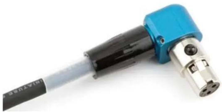
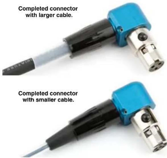
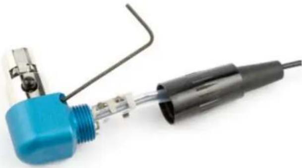
Close-up of a blue and black welding torch with metallic end cap (no text or symbols visible)Build a right angle TA5 or TA3 connector.
natural_image
Close-up of a blue and black mechanical tool with four circular ports, no visible text or symbols.Fill in for your records:
Serial Number:
Purchase Date:
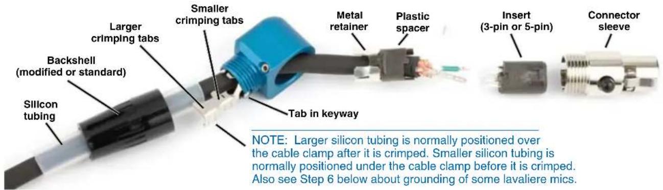
Parts Description and Details
The RATPAC (Right Angle T connector PACkage) is a versatile kit for building a right angle connector for use with the SR receiver or Lectrosonics transmitters. The 3-pin configuration is normally used for the rear panel audio outputs of the SR receiver. The 5-pin configuration is the standard connector for most belt pack transmitters and the front panel outputs on the 5P version of the SR receiver.
The kit includes a standard TA5F connector, a 3-pin insert, modified cable clamp, modified backshell, tubing, set screws with wrench, and a machined aluminum right angle housing.
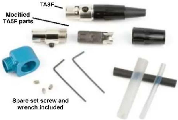
The right angle housing is a unique machined aluminum part that adapts a TA Series connector to work with a range of cable sizes and 3-pin or 5-pin inserts.
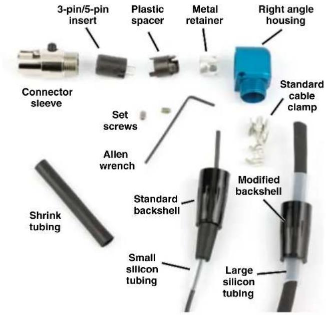
A standard TA connector sleeve is used with either a 3-pin or 5-pin insert and a modified cable clamp. The insert nests inside the sleeve and is held in place by a spacer and metal retainer. The sleeve is held in place by two set screws in the machined aluminum housing.
The shrink tubing can be used wherever it is useful to provide an additional strain relief. Cable is not included in the kit and is shown only to illustrate the use of the large and small silicon tubing.
Assembly
The example shown here illustrates an assembly with a larger cable and 3-pin insert, which could be used with the SREXT rear panel on the SR receiver.
Step 1
Install the set screws into the right angle housing. Turn them in a few turns, but do not tighten them. Slide all the parts onto the cable in the order shown above.
Step 2
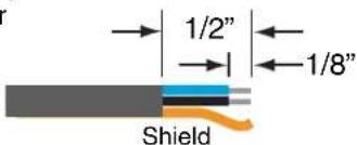
Strip the outer insulation of the cable back about 1/2 inch. Strip the insulation on the inner wires back about 1/8 inch.
Step 3
Solder the wires onto the pins on the insert as needed.
For the SR receiver, refer to its manual for pinouts.
http://www.lectrosonics.com/manuals/SRman.pdf
For microphones to be used with Lectrosonics transmitters, refer to the Servo Bias Mic Wiring document.
http://www.lectrosonics.com/service/ServoBiasWiring.pdf
Step 4
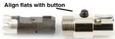
Slide the spacer up, align the flats on it and then attach it to the insert. Make sure the metal retainer is in position on the plastic spacer and slide the assembly into the connector sleeve. The flats must be aligned with the black button on the sleeve for the assembly to fully nest inside the sleeve.
Step 5
Orient the connector sleeve in the desired position while the cable can freely rotate inside the housing.
Gently slide the cable and connector assembly back through the housing until the connector is seated.
Apply pressure to make sure the connector assembly is completely seated in the housing. Insert the long end of the allen wrench and tighten the two set screws to secure the connector sleeve.
natural_image
Close-up of a soldering iron with blue and black tip connectors (no text or symbols visible)IMPORTANT: Connect the cable into the receiver or microphone and make sure it is working before crimping the cable clamp.
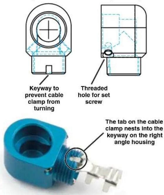
Slide the cable clamp into the housing, making sure the tab seats in the keyway on the housing. Gently push the cable into the housing to leave a little slack in the wires before crimping.
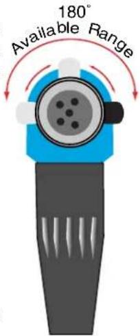
DO NOT ROTATE THE CONNECTOR SLEEVE MORE THAN 90 DEGREES IN TRYING TO ORIENT THE CABLE EXIT DIRECTION.
Step 6
Crimp the tabs on the cable clamp. If it is necessary to ground the housing to the cable, use the smaller cable clamp tabs to grab the cable shield. The larger tabs should
always go over the cable insulation and the tubing to keep the insulation from working up the cable. The housing will normally ground to the transmitter case through the retainer, but some lavalieres really like to have the cable clamp tabs grab the shield for better RF rejection.
Step 7
Slide the backshell over the clamp and thread it onto the housing.
LIMITED ONE YEAR WARRANTY
The equipment is warranted for one year from date of purchase against defects in materials or workmanship provided it was purchased from an authorized dealer. This warranty does not cover equipment which has been abused or damaged by careless handling or shipping. This warranty does not apply to used or demonstrator equipment.
Should any defect develop, Lectrosonics, Inc. will, at our option, repair or replace any defective parts without charge for either parts or labor. If Lectrosonics, Inc. cannot correct the defect in your equipment, it will be replaced at no charge with a similar new item. Lectrosonics, Inc. will pay for the cost of returning your equipment to you.
This warranty applies only to items returned to Lectrosonics, Inc. or an authorized dealer, shipping costs prepaid, within one year from the date of purchase.
This Limited Warranty is governed by the laws of the State of New Mexico. It states the entire liability of Lectrosonics Inc. and the entire remedy of the purchaser for any breach of warranty as outlined above. NEITHER LECTROSONICS, INC. NOR ANYONE INVOLVED IN THE PRODUCTION OR DELIVERY OF THE EQUIPMENT SHALL BE LIABLE FOR ANY INDIRECT, SPECIAL, PUNITIVE, CONSEQUENTIAL, OR INCIDENTAL DAMAGES ARISING OUT OF THE USE OR INABILITY TO USE THIS EQUIPMENT EVEN IF LECTROSONICS, INC. HAS BEEN ADVISED OF THE POSSIBILITY OF SUCH DAMAGES. IN NO EVENT SHALL THE LIABILITY OF LECTROSONICS, INC. EXCEED THE PURCHASE PRICE OF ANY DEFECTIVE EQUIPMENT.
This warranty gives you specific legal rights. You may have additional legal rights which vary from state to state.