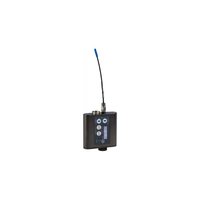
LMb/X - Wireless transmitter Lectrosonics - Free user manual and instructions
Find the device manual for free LMb/X Lectrosonics in PDF.


| Product Type | Wireless Belt-Pack Digital Transmitter |
| Brand | Lectrosonics |
| Model | LMb/X |
| Frequency Range | 470 – 614 MHz (UHF) |
| RF Output Power | 100 mW (typical) |
| Audio Input | TA5M (5-pin) for lavalier or headset microphone |
| Audio Modulation | Digital (DSP-based) |
| Frequency Response | 20 Hz – 20 kHz (±1 dB) |
| Power Source | 2 AA alkaline batteries (or rechargeable NiMH) |
| Battery Life | Approximately 10–12 hours (alkaline) |
| Dimensions (H x W x D) | 3.5 x 2.5 x 0.75 in (88.9 x 63.5 x 19.1 mm) |
| Weight (with batteries) | 4.5 oz (128 g) |
| Antenna | Removable, BNC connector |
| Controls | Power, Mute (push-button), Gain (rotary encoder) |
| Display | LCD screen for frequency, battery status, audio level |
| Operating Range | Up to 300 ft (90 m) line-of-sight |
| Maintenance | Clean with soft, dry cloth; avoid liquids; store in cool, dry place |
| Safety | Keep away from moisture; do not drop; avoid extreme temperatures |
| Spare Parts | Battery door, antenna, belt clip available |
| Reparability | User-replaceable batteries and antenna; other repairs should be performed by qualified technician |
Frequently Asked Questions - LMb/X Lectrosonics
User questions about LMb/X Lectrosonics
0 question about this device. Answer the ones you know or ask your own.
Ask a new question about this device
Download the instructions for your Wireless transmitter in PDF format for free! Find your manual LMb/X - Lectrosonics and take your electronic device back in hand. On this page are published all the documents necessary for the use of your device. LMb/X by Lectrosonics.
USER MANUAL LMb/X Lectrosonics
Digital Hybrid Wireless® UHF Belt Pack Transmitter
LMb, LMb/E01, LMb/E06, LMb/X
CE
UK CA
Follow Us On:


Fill in for your records:
Serial Number:
Purchase Date:
Featuring
Digital Hybrid
Wireless®

Quick Start Steps
1) Install good batteries and turn power on (see pages 5 and 6).
2) Set compatibility mode to match the receiver (see page 9).
3) Connect signal source and adjust input gain for optimum modulation level (see page 9).
4) Set StepSize and frequency to match receiver (see page 10). Also see receiver manual for scanning procedure.
5) Turn on the receiver and verify RF and audio signals are present (see receiver manual).
WARNING: Moisture, including talent's sweat, will damage the transmitter. Wrap the LMB in a plastic baggie or other protection to avoid damage or see LMCVR.

Table of Contents
Quick Start Steps....1
Introduction....3
About Digital Hybrid Wireless ....3
Frequency Agility ....3
Servo Bias Input and Wiring....3
DSP-controlled Input Limiter....3
LMb Block Diagram....4
No Pre-Emphasis/De-Emphasis 4
Pilot Tone Squelch....4
Battery Installation....5
Belt Clips 5
Operating Instructions....6
Battery Status LED Indicators....6
Powering On in Operating Mode....6
Powering On in Standby Mode 7
Powering Off 7
Navigating Menus....7
Locking/Unlocking Changes to Settings....7
Power Menu Options....7
Selecting Programmable Switch Functions ....8
Main Window Indicators....8
Selecting the Compatibility (Compat) Mode ....9
Connecting the Signal Source....9
Adjusting the Input Gain....9
Selecting Step Size....9
Selecting Frequency....10
Selecting Frequency Using Two Buttons....10
Helpful Features on Receivers 10
About Overlapping Frequency Bands....10
Selecting Audio Polarity (Phase)....11
Adjusting LCD Backlight 11
RF ON/OFF on the Menu....11
Selecting Battery Type....11
Restoring Default Settings 11
IR (infrared) Sync 11
5-Pin Input Jack Wiring....12
Microphone Cable Termination for Non-Lectrosonics Microphones....13
Input Jack Wiring for Different Sources....14
Microphone RF Bypassing....15
Line Level Signals....15
Wiring Diagram for MI39A Instrument Cable....15
Supplied and Optional Accessories....16
Troubleshooting....17
Specifications and Features....18
Service and Repair....19
Returning Units for Repair....19
Consumer Alert for US Users - FCC Order DA 10-92
Most users do not need a license to operate this wireless microphone system. Nevertheless, operating this microphone system without a license is subject to certain restrictions: the system may not cause harmful interference; it must operate at a low power level (not in excess of 50 milliwatts); and it has no protection from interference received from any other device. Purchasers should also be aware that the FCC is currently evaluating use of wireless microphone systems, and these rules are subject to change. For more information, call the FCC at 1-888- CALL-FCC (TTY: 1-888-TELL-FCC) or visit the FCC's wireless microphone website at www.fcc.gov/cgb/wirelessmicrophones. To operate wireless microphone systems at power greater than 50mW, you must qualify as a Part 74 user and be licensed. If you qualify and wish to apply for a license go to: http://www.fcc.gov/Forms/Form601/601.html
Introduction
The design of the LMB transmitter delivers the advanced technology and features of Digital Hybrid Wireless in a Lectrosonics belt-pack transmitter at a modest cost. Digital Hybrid Wireless combines a 24-bit digital audio chain with an analog FM radio link to eliminate a compandor and its artifacts, yet preserve the extended operating range and noise rejection of the finest analog wireless systems. Along with providing peerless audio quality with wide frequency response and dynamic range in Nu Hybrid mode, the technology used in the LMB includes DSP “compatibility modes” to allow the unit to be used with a variety of analog receivers by emulating the compandors found in earlier Lectrosonics analog wireless and IFB receivers, and certain receivers from other manufacturers (contact the factory for details).
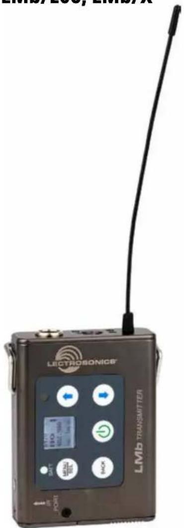
The housing is a rugged, machined aluminum package with removable, stainless steel wire belt clip. The input jack is a standard Lectrosonics 5-pin type for use with electret lavaliere mics, dynamic mics, musical instrument pickups and line level signals. The LEDs on the top panel allow quick and accurate level settings without having to view the receiver. The unit is powered by two AA batteries. The antenna is a super-rugged, permanently attached 1/4 wavelength design made of flexible galvanized steel cable.
The switching power supplies in the LMB provide constant voltages to the transmitter circuits from the beginning to the end of battery life, with output power remaining constant over the life of the battery. The input amplifier uses an ultra low noise op amp for quiet operation. Input gain is adjustable over a 44 dB range, with a DSP -controlled dual envelope input limiter to cleanly handle signal peaks over 30 dB above full modulation.
About Digital Hybrid Wireless
All wireless links suffer from channel noise to some degree, and all wireless microphone systems seek to minimize the impact of that noise on the desired signal. Conventional analog systems use compandors for enhanced dynamic range, at the cost of subtle artifacts (known as “pumping” and “breathing”). Wholly digital systems defeat the noise by sending the audio information in digital form, at the cost of some combination of power, bandwidth, operating range and resistance to interference.
The Lectrosonics Digital Hybrid Wireless ® system overcomes channel noise in a dramatically new way, digitally encoding the audio in the transmitter and decoding it in the receiver, yet still sending the encoded information via an analog FM wireless link. This proprietary algorithm is not a digital implementation of an analog compandor but a technique which can be accomplished only in the digital domain.
Since the RF link between transmitter and receiver is FM, channel noise will increase gradually with increased operating range and weak signal conditions,
however, the Digital Hybrid Wireless system handles this situation elegantly with rarely audible audio artifacts as the receiver approaches its squelch threshold. In contrast, a purely digital system tends to drop the audio suddenly during brief dropouts and weak signal conditions. The Digital Hybrid Wireless system simply encodes the signal to use a noisy channel as efficiently and robustly as possible, yielding audio performance that rivals that of purely digital systems, without the power, noise and bandwidth problems inherent in digital transmission. Because it uses an analog FM link, Digital Hybrid Wireless enjoys all the benefits of conventional FM wireless systems, such as excellent range, efficient use of RF spectrum, and long battery life.
Frequency Agility
Frequency selection is provided in 100 kHz or 25 kHz steps. Frequencies are displayed on the LCD in MHz and in a hex code used with earlier Lectrosonics equipment.
Wide-Band Deviation
Deviation has a direct effect on the dynamic range and signal to noise ratio of an FM system. The greater the deviation, the wider the dynamic range and the better the signal to noise ratio. In the Digital Hybrid Wireless * mode, the system operates with a maximum of +/-75 kHz of deviation. The resulting 180 kHz of occupied bandwidth just fits inside the government specified spectral mask of 200 kHz. In order to make this possible, an advanced, DSP-controlled limiter is used to prevent signal peaks from exceeding the maximum allowed bandwidth, but not cause distortion.
The result of all this is that the audio quality is outstanding, rivaling a hard-wired microphone. The system delivers a very wide dynamic range, and can handle loud signal peaks without distortion.
Servo Bias Input and Wiring
The LMB input preamp is a unique design that delivers audible improvements over conventional transmitter inputs. The transmitters are easier to use and much harder to overload. It is not necessary to introduce pads on some mics to prevent overload of the input stage, divide the bias voltage down for some low voltage mics, or reduce the limiter range at minimum gain settings.
Two different microphone wiring schemes are available to simplify and standardize the configuration. Simplified 2-wire and 3-wire configurations provide several arrangements designed for use only with servo bias inputs to take full advantage of the pre-amp circuitry. Other wiring schemes are compatible with Servo Bias and conventional inputs.
A line level input wiring provides an extended frequency response with an LF roll-off at 35 Hz for use with instruments and line level signal sources.
DSP-controlled Input Limiter
The transmitter employs a digitally-controlled analog audio limiter prior to the analog-to-digital converter. The limiter has a range greater than 30 dB for excellent overload protection. A dual release envelope makes the limiter acoustically transparent while maintaining low distortion. It can be thought of as two limiters in series, connected as a fast attack and release limiter followed by a slow attack and release limiter. The limiter recovers quickly from brief transients, so that its action is hidden from the listener, but recovers slowly from sustained high levels to keep audio distortion low and preserve short term dynamic changes in the audio.
No Pre-Emphasis/De-Emphasis
Because the signal to noise ratio of the Digital Hybrid Wireless ® system is so high, there is no need for conventional pre-emphasis (HF boost) in the transmitter and de-emphasis (HF roll off) in the receiver. Thus, the potential distortion problems associated with pre-emphasis and de-emphasis are eliminated.
Pilot Tone Squelch
The squelch system in a receiver is a method of muting the audio when the RF signal conditions are too poor to produce usable audio. While not all squelch systems work the same way, the goal is always the same: to discard noise and unusable audio.
The Digital Hybrid Wireless system employs a DSP-generated supersonic tone (pilot tone), using it as a kind of signature, so the receiver can mute even strong signals that aren't from the appropriate transmitter. The pilot tone also helps to ensure that the receiver is quiet when the transmitter is turned on and off.
256 different pilot tones provide reliable operation in multi-channel wireless systems. A different tone is generated every 100 kHz across the tuning range of the system, so that a tone is not repeated until it is 25.6 MHz above or below the previous one.
LMb Block Diagram
![graph TD A["Input Jack"] --> B["Servo Bias Supply"] B --> C["Bias Voltage 0, 2 or 4V"] C --> D["Input Preamp"] D --> E["Hi/Lo Pass Filter"] E --> F["AUDIO"] F --> G["A-D Converter 11001001"] F --> H["D-A Converter 11001001"] G --> I["I2S"] H --> J["I2S"] I --> K["Digital Signal Processor"] J --> K K…](/content/2026/05/1045798/images/ac0b77c04c2bdb5a9fd430c01d4a0460d9c5256fadeb0b6595782a3c17682380.jpg)
Battery Installation
The transmitter is powered by two AA batteries. We recommend using alkaline, lithium, or rechargeable batteries for longest life. Standard zinc-carbon batteries marked “heavy-duty” or “long-lasting” are not adequate.
WARNING: Risk of explosion if the battery is replaced by an incorrect type.
The battery status circuitry compensates for the difference in voltage drop between alkaline and lithium batteries across their usable life, so it's important to select the correct battery type in the menu.
Because rechargeable batteries run down quite abruptly, using the Power LED to verify battery status will not be reliable. However, it is possible to track battery status using the Battery Timer function available in Lectrosonics Digital Hybrid Wireless receivers.
Push outward on the Battery Compartment Door and lift it to open.

Insert the batteries according to the markings inside the battery compartment.
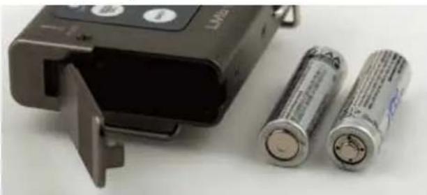
If the batteries are inserted incorrectly, the door will close but the unit will not operate.
The battery contacts can be cleaned with alcohol and a cotton swab, or a clean pencil eraser. Be sure not to leave any remnants of the cotton swab or eraser crumbs inside the compartment.

Belt Clips
The wire belt clip may be removed by pulling the ends out of the holes in the sides of the case. Use pliers to grasp the wire and avoid scratching the surface of the housing. Pliers also help when installing the clip.
An optional spring-loaded, hinged belt clip (model number BCSLEBN) is also available. This clip is attached by removing the plastic hole cap on the back of the housing and mounting the clip with the supplied screw.
Operating Instructions

Battery Status LED Indicators
Alkaline, lithium or rechargeable batteries can be used to power the transmitter. The type of batteries in use are selectable in a menu on the LCD.
When alkaline or lithium batteries are being used, the LED labeled BATT on the keypad glows green when the batteries are good. The color changes to red when the they are nearing the end of life. When the LED begins to blink red, there will be only a few minutes remaining.
The exact point at which the LEDs turn red will vary with battery brand and condition, temperature and power consumption. The LEDs are intended to simply catch your attention, not to be an exact indicator of remaining time.
A weak battery will sometimes cause the LEDs to glow green immediately after the transmitter is turned on, but it will soon discharge to the point where the LED will turn red or the unit will turn off completely.
Rechargeable batteries give little or no warning when they are depleted. If you wish to use these batteries in the transmitter, you will need to manually keep track of the operating time to prevent interruptions caused by dead batteries. Many Lectrosonics receivers have a timer function to keep track of battery runtime.
The Power/Function LED on the top panel will mirror the keypad LED unless the programmable switch is set to the Mute or Talkback mode, and the switch is turned on.
NOTE: The battery timer feature in many Lectrosonics receivers is very helpful in measuring battery runtime when using rechargeable batteries. Refer to the receiver instructions for details on using the timer.
Powering On in Operating Mode
Press and hold the Power Button ⏻ for several seconds until a counter on the LCD progresses from 1 through 3, followed by a display of the model, firmware version, frequency band and compatibility mode.

When you release the button, the unit will be operational with the RF output turned on and the Main Window displayed. Only the second and third screens will appear when the programmable function switch is used to turn on the power.
Powering On in Standby Mode
A brief press of the Power Button ⏻, releasing it before the counter has reached 3, will turn the unit on with the RF output turned off. In this Standby Mode,
the menus can be browsed to make settings and adjustments without the risk of interfering with other wireless systems nearby.

Release Power Button before the counter reaches 3 to enter standby mode
After settings and adjustments are made, press the power button again to turn the unit off.
NOTE: Also see the section entitled Power Menu for the AutoOn feature.
Powering Off

From any screen, power can be turned off by selecting Pwr Off in the power menu or holding the Power Button @in and waiting for the countdown, EXCEPT if the top panel switch is configured for this function.
If the power button is released, or the top panel switch is turned back on again before the countdown is completed, the unit will remain turned on and the LCD will return to the same screen or menu that was displayed previously.
NOTE: When the top panel switch is configured as a power switch, that is the only way to turn the unit off.
Navigating Menus
The LCD and keypad interface make it easy to browse the menus and make the selections for the setup the user needs. When the unit is powered up in either the operating or the standby mode, press MENU/SEL on the keypad to enter a menu structure on the LCD. Use the ① and ② arrow buttons to select the menu item. Then press the MENU/SEL button to enter the menu.



The prompt in the upper right corner may display one or both arrows, depending upon what adjustment can be made. If the changes are locked, a small padlock symbol will appear.
Locking/Unlocking Changes to Settings
Changes to the settings can be locked.


A small padlock symbol will appear on adjustment screens when changes have been locked.
When changes are locked, several controls and actions can still be used:
- Settings can still be unlocked
- Menus can still be browsed
• Programmable switch still works
- Power can still be turned off by using the power menu or removing the batteries.
Power Menu Options
A special options menu is provided by pressing the power button ⏻ quickly when the unit is turned on in either the Operating or Standby modes. Use the ⏻ and ⏻ arrow buttons to select the menu item.
- Resume - returns to the previous mode and screen
- Pwr Off - turns the unit off
- Rf On? - enters a screen to enable the operating or standby modes
- AutoOn? - allows the unit to automatically turn back on after a power failure or when fresh batteries are installed (works in the operating mode only)
- Backlit - adjusts the duration of the LCD back light to 30 seconds or 5 minutes, or to remain on
• LED Off - turns the LEDs on (Normal) or off (Dark) - About - displays the installed firmware version
- Blk606? - Band B1 and C1 LMb transmitters can be used with legacy Block 606 Lectrosonics receivers by invoking a special Block 606 legacy mode (Introduced in Firmware version v2.12) so that the correct pilot tones will be present. Use the ↑ and ↓ arrow buttons to select Legacy and press MENU/SEL to save. For E01 (European) modes only.
NOTE: Neither Band B1 nor Band C1 includes all Block 606 frequencies.
"Legacy" refers to SRb/E01-606 receivers, as well as the original Venue (VRMWBL with VRS/E01-606 modules).
Selecting Programmable Switch Functions
The programmable switch on the top panel can be configured using the menu to provide several functions:
• Power - turns the power on and off
- Mute - mutes the audio when switched on
- TalkBk (talkback) - redirects the audio to a different output channel on the receiver (with receivers that offer this function)
• (none) - disables the switch


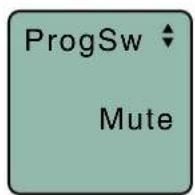

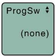
Use the ↑ and ↓ arrow buttons to select the desired function or disable the switch
NOTE: The programmable switch will continue to operate whether or not keypad changes are locked.
Main Window Indicators
The Main Window displays the band number, Stand-by or Operating mode, operating frequency, audio level, battery status and programmable switch function. When the frequency step size is set at 100 kHz, the LCD will look like the following.

When the frequency step size is set to 25 kHz, the hex number is smaller and may include a fraction.
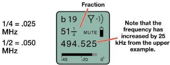
Changing the step size never changes the frequency. It only changes the way the user interface works. If the frequency is set to a fractional increment between even 100 kHz steps and the step size is changed to 100 kHz, the hex code will be replaced by two asterisks on the main screen and the frequency screen.
Frequency set to fractional 25 kHz step, but step size changed to 100 kHz.

If the programmable switch function is set for Mute, the Main Window will indicate that the function is enabled.

When the switch is turned on, the mute icon appearance will change, the word MUTE will blink at the bottom of the display, and the power/function LED will blink blue.

If the programmable switch function is set for Talkback, the Main Window will indicate that the function is enabled but not active.

When the programmable switch is turned on, the talkback icon appearance will change and the power/function LED will glow blue.

Selecting the Compatibility (Compat) Mode
When used with a Lectrosonics Digital Hybrid Wireless * receiver, the best audio quality will be achieved with the system set to the Nu Hybrid compatibility mode.

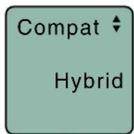
Use the UP and DOWN arrows to select the desired mode, then press the BACK button twice to return to the Main Window.
Compatibility modes are as follows. See Specifications for the modes that correspond to your specific model:
Receiver Models LCD menu item
- Mode 3:* Mode 3
- Nu Hybrid: Nu Hybrid
• IFB Series: IFB Mode
Mode 3* works with certain non-Lectrosonics models.
Nu Hybrid works with all Lectrosonics Digital Hybrid receivers. The receiver must also be set to the Nu Hybrid compatibility mode.
IFB Series works with Lectrosonics IFB R1/R1a analog receivers.
NOTE: If your Lectrosonics receiver does not have Nu Hybrid mode, set the receiver to Euro Digital Hybrid Wireless® (EU Dig. Hybrid).
* Contact the factory for details of this mode
Connecting the Signal Source
Microphones, line level audio sources and instruments can be used with the transmitter. Refer to the section entitled Wiring Hookups for Different Sources for details on the correct wiring for microphones to take full advantage of the Servo Bias circuitry.
Adjusting the Input Gain
The two bicolor Modulation LEDs on the control panel and keypad provide a visual indication of the audio signal level entering the transmitter. The LEDs will glow either red or green to indicate modulation levels as shown in the following table.
Signal Level -20 LED -10 LED
| Less than -20 dB | Off | Off | ● | |
| -20 dB to -10 dB | Green | Off | ● | |
| -10 dB to +0 dB | Green | Green | ● | |
| +0 dB to +10 dB | Red | Green | ||
| Greater than +10 dB | Red | Red |
Rio Rancho, NM
NOTE: Full modulation is achieved at 0 dB, when the “-20” LED first turns red. The limiter can cleanly handle peaks up to 30 dB above this point.
It is best to go through the following procedure with the transmitter in the standby mode so that no audio will enter the sound system or recorder during adjustment.
1) With fresh batteries in the transmitter, power the unit on in the standby mode (see previous section Powering On in Standby Mode).
2) Navigate to the Gain setup screen.


3) Prepare the signal source. Position a microphone the way it will be used in actual operation and have the user speak or sing at the loudest level that occur during use, or set the output level of the instrument or audio device to the maximum level that will be used.
4) Use the ⏻ and ⏻ arrow buttons to adjust the gain until the -10 dB glows green and the -20 dB LED starts to flicker red during the loudest peaks in the audio.
5) Once the audio gain has been set, the signal can be sent through the sound system for overall level adjustments, monitor settings, etc.
6) If the audio output level of the receiver is too high or low, use only the controls on the receiver to make adjustments. Always leave the transmitter gain adjustment set according to these instructions, and do not change it to adjust the audio output level of the receiver.
Selecting Step Size
This menu item allows frequencies to be selected in either 100 kHz or 25 kHz increments.
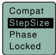


If the desired frequency ends in .025, .050 or .075 MHz, the 25 kHz step size must be selected.
Normally, the receiver is used to find a clear operating frequency. All Lectrosonics Digital Hybrid Wireless receivers provide a scanning function to quickly and easily find prospective frequencies with little or no RF interference. In other cases, a frequency may be specified by officials at a large event such as the Olympics or a major league ball game. Once the frequency is determined, set the transmitter to match the associated receiver.
Selecting Frequency
The setup screen for frequency selection offers several ways to browse the available frequencies.


Each field will step through the available frequencies in a different increment. The increments are also different in the 25 kHz mode from the 100 kHz mode.

A fraction will appear next to the hex code in the setup screen and in the main window when the frequency ends in .025, .050 or .075 MHz.

Fraction appears next to hex code in 25 kHz mode

Selecting Frequency Using Two Buttons
Hold the MENU/SEL button in, then use the ↑ and ↓ and arrow buttons for alternate increments.

Helpful Features on Receivers
To aid in finding clear frequencies, several Lectrosonics receivers offer a SmartTune feature that scans the tuning range of the receiver and displays a graphical report that shows where RF signals are present at different levels, and areas where there is little or no RF energy present. The software then automatically selects the best channel for operation.
Lectrosonics receivers equipped with an IR Sync function allow the receiver to set frequency, step size and compatibility modes on the transmitter via an infrared link between the two units.
About Overlapping Frequency Bands
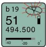
When two frequency bands overlap, it is possible to select the same frequency at the upper end of one and the lower end of the other. While the frequency will be the same, the pilot tones will be different, as indicated by the hex codes that appear.
In the following examples, the frequency is set to 494.500 MHz, but one is in band 470 and the other in band 19. This is done intentionally to maintain compatibility with receivers that tune across a single band. The band number and hex code must match the receiver to enable the correct pilot tone.
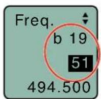
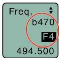
Make sure the band number and hex code match the receiver setting
Selecting Audio Polarity (Phase)
Audio polarity can be inverted at the transmitter so the audio can be mixed with other microphones without comb filtering. The polarity can also be inverted at the receiver outputs.


Adjusting LCD Backlight
For viewing the LCD in dimly lit conditions, the backlight can be turned on continuously or set to turn off automatically after either 30 seconds or 5 minutes.


RF ON/OFF on the Menu
The RF output of the transmitter can be turned off and on with a menu item on the LCD to switch from the standby mode to the operating mode.


Selecting Battery Type
The voltage drop over the life of different batteries varies by type and brand. Be sure to set the correct battery type for accurate indications and warnings. The menu offers alkaline or lithium types.
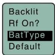
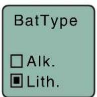
If you are using rechargeable batteries, it is better to use the timer function on the receiver to monitor the battery life rather than the indicators on the transmitter. Rechargeable batteries maintain a fairly constant voltage across the operating time on each charge and stop working abruptly, so you will have little or no warning as they reach the end of operation. The timer is available on all Lectrosonics Digital Hybrid Wireless' receivers.
Restoring Default Settings
This is used to restore the factory settings.


IR (infrared) Sync
The opening on the side panel is an IR port for quick setup using a receiver with this capability. The transfer is initiated with a switch on the receiver.
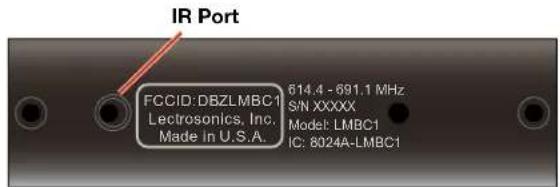
The receiver can transfer the settings for Frequency, Step Size and Compatibility mode to the transmitter via the IR ports. When the settings are successfully transferred, OK will appear on the transmitter LCD. If a mismatch exists, an error message will appear on the transmitter LCD indicating the nature of the problem.


5-Pin Input Jack Wiring
The wiring diagrams included in this section represent the basic wiring necessary for the most common types of microphones and other audio inputs. Some microphones may require extra jumpers or a slight variation on the diagrams shown.
It is virtually impossible to keep completely up to date on changes that other manufacturers make to their products, thus you may encounter a microphone that differs from these instructions. If this occurs please call our toll-free number listed under Service and Repair in this manual or visit our web site at:
www.lectrosonics.com

Audio input jack wiring:
PIN 1
Shield (ground) for positive biased electret lavaliere microphones. Shield (ground) for dynamic microphones and line level inputs.
PIN 2
Bias voltage source for positive biased electret lavaliere microphones that are not using servo bias circuitry and voltage source for 4 volt servo bias wiring.
PIN 3
Microphone level input and bias supply.
PIN 4
Bias voltage selector for Pin 3.
Pin 3 voltage depends on Pin 4 connection.
Pin 4 tied to Pin 1: 0 V
Pin 4 Open: 2 V
Pin 4 to Pin 2: 4 V
PIN 5
Line level input for tape decks, mixer outputs, musical instruments, etc.
TA5F Latchlock

Insert

Insulator

Backshell with strain relief
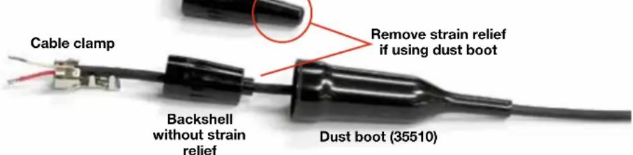
Note: If you use the dust boot, remove the rubber strain relief that is attached to the TA5F cap, or the boot will not fit over the assembly.
Installing the Connector:
1) If necessary, remove the old connector from the microphone cable.
2) Slide the dust boot onto microphone cable with the large end facing the connector.
3) If necessary, slide the 1/8-inch black shrink tubing onto the microphone cable. This tubing is needed for some smaller diameter cables to ensure there is a snug fit in the dust boot.
4) Slide the backshell over the cable as shown above. Slide the insulator over the cable before soldering the wires to the pins on the insert.
5) Solder the wires and resistors to the pins on the insert according to the diagrams shown in Wiring Hookups for Different Sources. A length of .065 OD clear tubing is included if you need to insulate the resistor leads or shield wire.
6) If necessary, remove the rubber strain relief from the TA5F backshell by simply pulling it out.
7) Seat the insulator on the insert. Slide the cable clamp over the and of the insulator and crimp as shown on the next page.
8) Insert the assembled insert/insulator/clamp into the latchlock. Make sure the tab and slot align to allow the insert to fully seat in the latchlock. Thread the backshell onto the latchlock.
Microphone Cable Termination for Non-Lectrosonics Microphones
TA5F Connector Assembly
![graph LR A["Component 1"] --> B["↔"] B --> C["↔"] C --> D["↔"] D --> E["↔"] E --> F["↔"]](/content/2026/05/1045798/images/c8b3504e1965303bf3b4ecb4b9a36f86ff58c9102720d1f15cf7fde3e796da30.jpg)
Mic Cord Stripping Instructions

Crimping to Shield and

Strip and position the cable so that the clamp can be crimped to contact both the mic cable shield and the insulation. The shield contact reduces noise with some microphones and the insulation clamp increases ruggedness.
NOTE: This termination is intended for UHF transmitters only. VHF transmitters with 5-pin jacks require a different termination. Lectrosonics lavaliere microphones are terminated for compatibility with VHF and UHF transmitters, which is different from what is shown here.
Wiring Hookups for Different Sources
In addition to the microphone and line level wiring hook-ups illustrated below, Lectrosonics makes a number of cables and adapters for other situations such as connecting musical instruments (guitars, bass guitars, etc.) to the transmitter. Visit www.lectrosonics.com and click on Accessories, or download the master catalog.
A lot of information regarding microphone wiring is also available in the FAQ section of the web site at:
http://www.lectrosonics.com/faqdb
Follow the instructions to search by model number or other search options.
Compatible Wiring for Both Servo Bias Inputs and Earlier Transmitters:
Fig. 1

Fig. 2
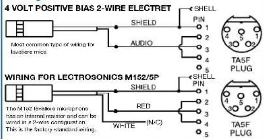
Fig. 3 - DPA Microphones

Fig. 4

Fig. 5 - Sanken COS-11 and others
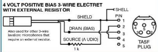
Fig. 6
LO-Z MICROPHONE LEVEL SIGNALS

Fig. 7

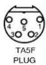
Fig. 8

Simple Wiring - Can ONLY be used with Servo Bias Inputs:
Servo Bias was introduced in 2005 and all transmitters with 5-pin inputs have been built with this feature since 2007.
Fig. 9
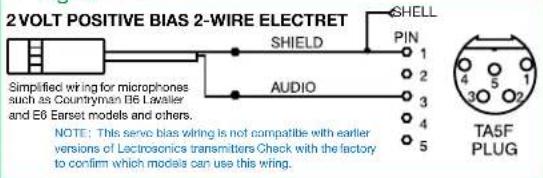
Fig. 10

Fig. 11

Microphone RF Bypassing
When used on a wireless transmitter, the microphone element is in the proximity of the RF coming from the transmitter. The nature of electret microphones makes them sensitive to RF, which can cause problems with microphone/transmitter compatibility. If the electret microphone is not designed properly for use with wireless transmitters, it may be necessary to install a chip capacitor in the mic capsule or connector to block the RF from entering the electret capsule.
Some mics require RF protection to keep the radio signal from affecting the capsule, even though the transmitter input circuitry is already RF bypassed.
If the mic is wired as directed, and you are having difficulty with squealing, high noise, or poor frequency response, RF is likely to be the cause.
The best RF protection is accomplished by installing RF bypass capacitors at the mic capsule. If this is not possible, or if you are still having problems, capacitors can be installed on the mic pins inside the TA5F connector housing. Refer to the diagram below for the correct locations of capacitors.
Use 330 pF capacitors. Capacitors are available from Lectrosonics. Please specify the part number for the desired lead style.
Leaded capacitors: P/N 15117
Leadless capacitors: P/N SCC330P
All Lectrosonics lavaliere mics are already bypassed and do not need any additional capacitors installed for proper operation.

Line Level Signals
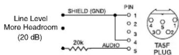
The normal wiring for line level signals is:
- Signal Hot to pin 5
- Signal Gnd to pin 1
- Pin 4 jumped to pin 1
This allows signal levels up to 3V RMS to be applied without limiting.
If more headroom is needed, insert a 20 k resistor in series with pin 5. Put this resistor inside the TA5F connector to minimize noise pickup.

See Fig. 8 on previous page
Wiring Diagram for MI39A Instrument Cable
The MI39ARA and MI39AST instrument cable assemblies allow an optimum match between musical instrument pickups and Lectrosonics transmitters with 5-pin input connectors.
The cables are wired to provide an extended low frequency response with a roll-off at 35 Hz.
Note: This cable is prewired and cannot be field modified. The cable is available in two configurations, MI39ARA (right angle 1/4" plug) and MI39AST (straight 1/4" plug).


Supplied Accessories
P/N 26526 Wire belt clip (installed on transmitter)
P/N 55008 AA battery caddy; 4-pack; blue
Optional Accessories
BCHINGED Hinged belt clip
LMCVR Silicone cover protects the LMb transmitter from moisture and dust.
M152/5P Lavaliere microphone; omnidirectional
MI33PRA Instrument cable; passive type for use with very high output pickups; right angle 1/4" plug
MI33PST Instrument cable; passive type for use with very high output pickups; straight 1/4" plug
MI39ARA Instrument cable; active type for use with most instrument pickups; right angle 1/4" plug
MI39AST Instrument cable; active type for use with most instrument pickups; straight 1/4"plug
MC35 Line level adapter cable; XLR-F to TA5F;37" length
MC41 Dynamic mic level adapter cable; XLR-Fto TA5F; 37" length
Troubleshooting
It is important that you follow these steps in the sequence listed.
Symptom:
Possible
Cause:
Transmitter Battery LED off 1. Batteries are inserted incorrectly.
when Power Switch "ON" 2. Batteries are low or dead.
No Transmitter Modulation LEDs
- Gain control turned all the way down.
when Signal Should be Present
-
Batteries are inserted incorrectly. Check power LED.
-
Mic capsule is damaged or malfunctioning.
- Mic cable damaged or miswired.
- Instrument Cable damaged or not plugged in.
- Musical instrument output level set too low.
Receiver Indicates RF But No Audio using an alternate source or cable
-
Audio source or cable connected to transmitter is defective. Try
-
Make sure the compatibility mode is the same on transmitter and receiver.
- Ensure musical instrument volume control is not set to minimum.
- Check for correct pilot tone indication on the receiver. See item on page 11 entitled About Overlapping Frequency Bands.
Receiver RF Indicator Off
- Ensure that the transmitter and receiver are set to the same
frequency, and that the hex code matches.
- Transmitter not turned on, or battery is dead.
- Receiver antenna missing or improperly positioned.
- Operating distance is too great.
- Transmitter may be set to the Standby Mode. See page 7.
No Sound (Or Low Sound Level), Receiver
- Receiver output level set too low.
Indicates Proper Audio Modulation
-
Receiver output is disconnected; cable is defective or miswired.
-
Sound system or recorder input is turned down.
Distorted Sound
- Transmitter gain (audio level) is too high. Check Modulation
LEDs on transmitter and receiver while distortion is being heard.
- Receiver output level may be mismatched with the sound system or recorder input. Adjust output level on receiver to the correct level for the recorder, mixer or sound system.
- Transmitter and receiver may not be set to the same compat mode. Some mis-matched combinations will pass audio.
- RF interference. Reset both transmitter and receiver to a clear channel. Use scanning function on receiver if available.
Wind Noise or Breath "Pops"
-
Reposition microphone, or use a larger windscreen, or both.
-
Omni-directional mics produce less wind noise and breath pops than directional types.
Hiss and Noise -- Audible Dropouts
-
Transmitter gain (audio level) far too low.
-
Receiver antenna missing or obstructed.
- Operating distance too great.
- RF interference. Reset both transmitter and receiver to a clear channel. Use scanning function on receiver if available.
- Musical instrument output set too low.
- Microphone capsule picking up RF noise. See item on page 15 entitled Microphone RF Bypassing.
Excessive Feedback (With Microphone) and/or reduce receiver output level.
-
Transmitter gain (audio level) too high. Check gain adjustment
-
Microphone too close to speaker system.
- Microphone is too far from user's mouth.
Specifications and Features
Operating Frequencies:
US: Band A1: 470.100 - 537.575 Band B1: 537.600 - 607.950
E01: Band A1: 470.100 - 537.575 Band B1: 537.600 - 614.375 Band 606: 606.000 - 631.500 Band C1: 614.400 - 691.175
E06: Band B1: 537.600 - 614.375 Band C1: 614.400 - 691.175
X: Band A1: 470.100 - 537.575 MHz Band B1: 537.600 - 614.375 MHz Band C1: 614.400 - 691.175 MHz
NOTE: It's the user's responsibility to select the approved frequencies for the region where the transmitter is operating
Frequency Selection Steps:
Selectable; 100 kHz or 25 kHz
RF Power output: E01: 50 mW E06: 100 mW EIRP X: 50 mW
Compatibility Modes:
US: Nu Hybrid, Mode 3, IFB
E01: Digital Hybrid, IFB
E06: 100 Mode, 200 Mode, Mode 3, Digital Hybrid, IFB, Mode 6, Mode 7
X: 100 Mode, 200 Mode, Mode 3, Digital Hybrid, IFB, Mode 6, Mode 7
Pilot tone:
25 to 32 kHz; 5 kHz deviation (Digital Hybrid mode) 3.5 kHz deviation (Nu Hybrid)
Frequency Stability:
± 0.002% US: Compliant with ETSI EN 300 422-1 v1.4.2 E01/E06/X: 60 dB below carrier
Spurious radiation:
-120 dBV (A-weighted) Nominal 2 mV to 300 mV, before limiting; Greater than 1V maximum, with limiting
Equivalent input noise:
Input level:
US: 2k Ohm E01/E06/X: Mic: 300 Ohm, Line: 2k Ohm (for E01/E06/X)
Input impedance:
DSP controlled, dual envelope "soft" limiter with greater than 30 dB range
Input limiter:
44 dB; digital control - Dual bicolor LEDs indicate modulation of -20, -10, 0 and +10 dB referenced to full modulation - LCD bar graph
Operating temp. range:
Celsius: -20° - 40° Farenheit: -5° - 104°
Audio Performance:
Frequency Response:
90 Hz to 20 kHz (+/-1dB) - NuHybrid 70 Hz to 20 kHz (+/-1dB) - Digital Hybrid
Low frequency roll-off:
-12 dB/octave; 70 Hz - Nu Hybrid
THD:
0.2% (typical)
SNR at receiver output:
Note: The dual envelope "soft" limiter provides exceptionally good handling of transients using variable
| SmartNR | No Limiting | w/Limiting |
| OFF | 103.5 | 108.0 |
| NORMAL | 107.0 | 111.5 |
| FULL | 108.5 | 113.0 |
attack and release time constants. Once activated, the limiter compresses 30+ dB of transmitter input range into 4.5 dB of receiver output range, thus reducing the measured figure for SNR without limiting by 4.5 dB
Controls:
- Top panel slide switch; programmable as power, mute, talkback or no (off) function
- Side panel membrane switches with LCD interface for power on/off and all setup and configuration controls
Audio Input Jack:
Switchcraft 5-pin locking (TA5F)
Antenna:
Galvanized steel, flexible wire
Battery:
Two AA lithium
Battery Life:
Duracell Ultra: 7 hours
Weight:
5 ounces (141 grams), including lithium AA batteries and wire belt clip
Dimensions:
3.2 x 2.4 x .8 in. (81 x 61 x 20 mm)
Emission Designator:
110KF3E (US)
180KF3E (E01, E06)
Specifications subject to change without notice.
For body worn operation, this transmitter model has been tested and meets the FCC RF exposure guidelines when used with the Lectrosonics accessories supplied or designated for this product. Use of other accessories may not ensure compliance with FCC RF exposure guidelines. Contact Lectrosonics if you have any questions or need more information about RF exposure using this product..
This device complies with FCC radiation exposure limits as set forth for an uncontrolled environment. This device should be installed and operated so that its antenna(s) are not colocated or operating in conjunction with any other antenna or transmitter.
This device complies with Industry Canada radiation exposure limits as set forth for a controlled “professional” use only.
If your system malfunctions, you should attempt to correct or isolate the trouble before concluding that the equipment needs repair. Make sure you have followed the setup procedure and operating instructions. Check the interconnecting cables and then go through the Troubleshooting section in this manual.
We strongly recommend that you do not try to repair the equipment yourself and do not have the local repair shop attempt anything other than the simplest repair. If the repair is more complicated than a broken wire or loose connection, send the unit to the factory for repair and service. Don't attempt to adjust any controls inside the units. Once set at the factory, the various controls and trimmers do not drift with age or vibration and never require readjustment. There are no adjustments inside that will make a malfunctioning unit start working.
LECTROSONICS' Service Department is equipped and staffed to quickly repair your equipment. In warranty repairs are made at no charge in accordance with the terms of the warranty. Out-of-warranty repairs are charged at a modest flat rate plus parts and shipping. Since it takes almost as much time and effort to determine what is wrong as it does to make the repair, there is a charge for an exact quotation. We will be happy to quote approximate charges by phone for out-of-warranty repairs.
Returning Units for Repair
For timely service, please follow the steps below:
A. DO NOT return equipment to the factory for repair without first contacting us by email or by phone. We need to know the nature of the problem, the model number and the serial number of the equipment. We also need a phone number where you can be reached 8 A.M. to 4 P.M. (U.S. Mountain Standard Time).
B. After receiving your request, we will issue you a return authorization number (R.A.). This number will help speed your repair through our receiving and repair departments. The return authorization number must be clearly shown on the outside of the shipping container.
C. Pack the equipment carefully and ship to us, shipping costs prepaid. If necessary, we can provide you with the proper packing materials. UPS is usually the best way to ship the units. Heavy units should be "double-boxed" for safe transport.
D. We also strongly recommend that you insure the equipment, since we cannot be responsible for loss of or damage to equipment that you ship. Of course, we insure the equipment when we ship it back to you.
Lectrosonics USA:
Mailing address: Shipping address: Telephone:
Lectrosonics, Inc. Lectrosonics, Inc. (505) 892-4501
PO Box 15900 581 Laser Rd. (800) 821-1121 Toll-free
Rio Rancho, NM 87174 Rio Rancho, NM 87124 (505) 892-6243 Fax
USA USA
Web:
E-mail:
www.lectrosonics.com
sales@lectrosonics.com
Lectrosonics Canada:
Mailing Address:
Telephone:
720 Spadina Avenue,
(416) 596-2202
Suite 600
(877) 753-2876 Toll-free
Toronto, Ontario M5S 2T9
(877-7LECTRO)
(416)
596-6648
E-mail:
Sales: colinb@lectrosonics.com
Service: joeb@lectrosonics.com
Fax
Self-Help Options for Non-Urgent Concerns
Our Facebook groups and weblists are a wealth of knowledge for user questions and information. Refer to:
Lectrosonics General Facebook Group: https://www.facebook.com/groups/69511015699
D Squared, Venue 2 and Wireless Designer Group: https://www.facebook.com/groups/104052953321109
The Wire Lists: https://lectrosonics.com/the-wire-lists.html

P.O. Box 15900 - Rio Rancho, NM - 87174 - USA
Phone: (800)821-1121 or (505)892-4501 - Fax: (505)892-6243
web: www.lectrosonics.com - email: sales@lectrosonics.com
Declaration of Conformity
LECTROSONICS, INC.
581 Laser Road
Rio Rancho, NM 87124 USA
Declare under our sole responsibility that the following product:
LMB/E01 Transmitter, UHF body-pack
to which this Declaration relates, is in conformity with the directives and standards listed below,
Radio Spectrum R&TTE 1999/5/EEC
Standard: EN 300 422 v1.4.2 (2011-08)
Test report: R1405232-422
EMC Directive 2004/108/EC
Standard: EN 301 489-1 v1.9.2 (2011-09)
Standard: EN 301 489-3 v1.4.1 (2008-09)
Test report: R1405232-12
Safety/Low Voltage Directive 2006/95/EC
Standard: EN 60950-1: 2006 + AC:2011
Test report: R1405232-3
Standard: EN 62311: 2008
Test report: R1405232-SAR
and is in conformity with Directive 2011/65/EU of the European Parliament and of the Council of 8 June 2011 (RoHS Recast).

Robert Cunnings
V.P. Engineering
Lectrosonics, Inc.
6 February 2015

Opinion Number: R1405232
DIRECTIVE 1999/5/EC
NOTIFIED BODY STATEMENT OF OPINION
Bay Area Compliance Laboratories Corp.
| Date of Issue: | 2015-02-06 |
| Applicant: | Lectrosonics, Inc.581 Laser Road, Rio Rancho, NM 87124, USA |
| Trade Name: | N/A |
| Model Number: | LMB/E01-A1, LMB/E01-B1, LMB/E01-C1, LMB/E01-D1 |
| Equipment Type: | UHF Wireless Microphone Transmitter |
| Serial Number: | S/N 1 (Block A1), S/N 2 (Block B1), S/N 3 (Block C1), S/N 4 (Block D1) |
| Block A1: 470.100-537.575 MHzBlock B1: 537.600-614.375 MHzBlock C1: 614.400-691.175 MHz | |
| Frequency Range: | Block D1: 691.200-767.975 MHz |
| Channel Bandwidth: | 25 kHz, 100 kHz |
| RF Output Power: | 50 mW |
| Modulation Type: | FM |
| Antenna Type: | Integrated Dipole Antenna, 2.15 dBi |
| Notified Body 1313: | Bay Area Compliance Laboratories Corp.1274 Anvilwood Ave., Sunnyvale, CA 94089, USATel: 1-(408)-732-9162 Fax: 1-(408)-732-9164www.baclcorp.com |
| Essential Requirements | Specifications/Standards | Document Identification | Results |
| Radio Spectrum, Article 3.2 | ETSI EN 300 422 V1.4.2 (2011-08) | R1405232-422 | Compliant |
| EMC, Article 3.1(b) | ETSI EN 301 489-1 V1.9.2 (2011-09)ETSI EN 301 489-3 V1.4.1 (2008-09) | R1405232-12 | Compliant |
| Safety, Article 3.1(a) | EN 60950-1: 2006 + AC: 2011 | R1405232-3 | Compliant |
| Health Article 3.1(a) | EN 62311: 2008 | R1405232-SAR | Compliant |
Our opinion in accordance with Annex IV of Council Directive 1999/5/EC on radio equipment and telecommunications equipment and the mutual recognition of their conformity is that the apparatus identified above complies with the requirements of that directive stated above.
Marking: It is recommended that the product bear the CE mark, the notified body number(s) as depicted to the right, only when all the essential requirements have been met, and a Manufacturer's Declaration of Conformity (EN 45014) has been filed with the European Commission
Number of Annexes to this statement: 1
CE1313①

Authorized by:

John Chan, Technical Expert
End Validity Date: June 13, 2017
Bay Area Compliance Laboratories Corp. 1274 Anvilwood Ave, Sunnyvale, CA 94089, U.S.A.
Tel: 1-(408)-732-9162 Fax: 1-(408)-732-9164
C1003-E
LIMITED ONE YEAR WARRANTY
The equipment is warranted for one year from date of purchase against defects in materials or workmanship provided it was purchased from an authorized dealer. This warranty does not cover equipment which has been abused or damaged by careless handling or shipping. This warranty does not apply to used or demonstrator equipment.
Should any defect develop, Lectrosonics, Inc. will, at our option, repair or replace any defective parts without charge for either parts or labor. If Lectrosonics, Inc. cannot correct the defect in your equipment, it will be replaced at no charge with a similar new item. Lectrosonics, Inc. will pay for the cost of returning your equipment to you.
This warranty applies only to items returned to Lectrosonics, Inc. or an authorized dealer, shipping costs prepaid, within one year from the date of purchase.
This Limited Warranty is governed by the laws of the State of New Mexico. It states the entire liability of Lectrosonics Inc. and the entire remedy of the purchaser for any breach of warranty as outlined above. NEITHER LECTROSONICS, INC. NOR ANYONE INVOLVED IN THE PRODUCTION OR DELIVERY OF THE EQUIPMENT SHALL BE LIABLE FOR ANY INDIRECT, SPECIAL, PUNITIVE, CONSEQUENTIAL, OR INCIDENTAL DAMAGES ARISING OUT OF THE USE OR INABILITY TO USE THIS EQUIPMENT EVEN IF LECTROSONICS, INC. HAS BEEN ADVISED OF THE POSSIBILITY OF SUCH DAMAGES. IN NO EVENT SHALL THE LIABILITY OF LECTROSONICS, INC. EXCEED THE PURCHASE PRICE OF ANY DEFECTIVE EQUIPMENT.
This warranty gives you specific legal rights. You may have additional legal rights which vary from state to state.
- DIGITAL HYBRID WIRELESS® UHF BELT PACK TRANSMITTER
- FEATURING
- DIGITAL HYBRID
- WIRELESS®
- QUICK START STEPS
- TABLE OF CONTENTS
- CONSUMER ALERT FOR US USERS - FCC ORDER DA 10-92
- INTRODUCTION
- ABOUT DIGITAL HYBRID WIRELESS
- FREQUENCY AGILITY
- WIDE-BAND DEVIATION
- SERVO BIAS INPUT AND WIRING
- DSP-CONTROLLED INPUT LIMITER
- NO PRE-EMPHASIS/DE-EMPHASIS
- PILOT TONE SQUELCH
- BATTERY INSTALLATION
- BELT CLIPS
- OPERATING INSTRUCTIONS
- BATTERY STATUS LED INDICATORS
- POWERING ON IN OPERATING MODE
- POWERING ON IN STANDBY MODE
- POWERING OFF
- NAVIGATING MENUS
- LOCKING/UNLOCKING CHANGES TO SETTINGS
- POWER MENU OPTIONS
- SELECTING PROGRAMMABLE SWITCH FUNCTIONS
- MAIN WINDOW INDICATORS
- SELECTING THE COMPATIBILITY (COMPAT) MODE
- RECEIVER MODELS LCD MENU ITEM
- CONNECTING THE SIGNAL SOURCE
- ADJUSTING THE INPUT GAIN
- SELECTING STEP SIZE
- SELECTING FREQUENCY
- SELECTING FREQUENCY USING TWO BUTTONS
- HELPFUL FEATURES ON RECEIVERS
- ABOUT OVERLAPPING FREQUENCY BANDS
- SELECTING AUDIO POLARITY (PHASE)
- ADJUSTING LCD BACKLIGHT
- RF ON/OFF ON THE MENU
- SELECTING BATTERY TYPE
- RESTORING DEFAULT SETTINGS
- IR (INFRARED) SYNC
- 5-PIN INPUT JACK WIRING
- AUDIO INPUT JACK WIRING
- PIN 1
- PIN 2
- PIN 3
- PIN 4
- PIN 5
- INSTALLING THE CONNECTOR
- MICROPHONE CABLE TERMINATION FOR NON-LECTROSONICS MICROPHONES
- WIRING HOOKUPS FOR DIFFERENT SOURCES
- HTTP://WWW.LECTROSONICS.COM/FAQDB
- COMPATIBLE WIRING FOR BOTH SERVO BIAS INPUTS AND EARLIER TRANSMITTERS
- SIMPLE WIRING - CAN ONLY BE USED WITH SERVO BIAS INPUTS
- MICROPHONE RF BYPASSING
- LINE LEVEL SIGNALS
- WIRING DIAGRAM FOR MI39A INSTRUMENT CABLE
- SUPPLIED ACCESSORIES
- OPTIONAL ACCESSORIES
- TROUBLESHOOTING
- SYMPTOM
- POSSIBLE
- CAUSE
- NO TRANSMITTER MODULATION LEDS
- WHEN SIGNAL SHOULD BE PRESENT
- RECEIVER INDICATES RF BUT NO AUDIO USING AN ALTERNATE SOURCE OR CABLE
- RECEIVER RF INDICATOR OFF
- NO SOUND (OR LOW SOUND LEVEL), RECEIVER
- INDICATES PROPER AUDIO MODULATION
- DISTORTED SOUND
- WIND NOISE OR BREATH "POPS
- HISS AND NOISE -- AUDIBLE DROPOUTS
- EXCESSIVE FEEDBACK (WITH MICROPHONE) AND/OR REDUCE RECEIVER OUTPUT LEVEL
- SPECIFICATIONS AND FEATURES
- RETURNING UNITS FOR REPAIR
- SELF-HELP OPTIONS FOR NON-URGENT CONCERNS
- DECLARATION OF CONFORMITY
- DIRECTIVE 1999/5/EC
- NOTIFIED BODY STATEMENT OF OPINION
- LIMITED ONE YEAR WARRANTY
Brand : Lectrosonics
Model : LMb/X
Category : Wireless transmitter