RCI MEM2400 - Lock Dormakaba - Free user manual and instructions
Find the device manual for free RCI MEM2400 Dormakaba in PDF.

User questions about RCI MEM2400 Dormakaba
0 question about this device. Answer the ones you know or ask your own.
Ask a new question about this device
Download the instructions for your Lock in PDF format for free! Find your manual RCI MEM2400 - Dormakaba and take your electronic device back in hand. On this page are published all the documents necessary for the use of your device. RCI MEM2400 by Dormakaba.
USER MANUAL RCI MEM2400 Dormakaba
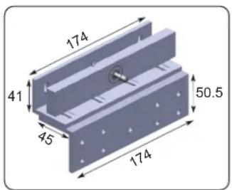
MEM2400LED Mechanical Electromagnetic Lock for Inward Opening Doors
Introduction
The patented MEM 2400LED Mechanical Electromagnet locking device is designed for securing all types of inward opening side hung hinged doors. The MEM lock has a holding force of up to 1000KG and is equipped with a LED light feature for Secure (green) / Insecure (red) local monitoring indication on the device. The MEM2400LED has been Fire Tested for up to 4 hours to both AS & BS Standards. The MEM2400LED locking device is capable of releasing under door back pressure (pre-load) of up to 70KG. The unit comes with an L&Z Bracket as standard.
Monitoring
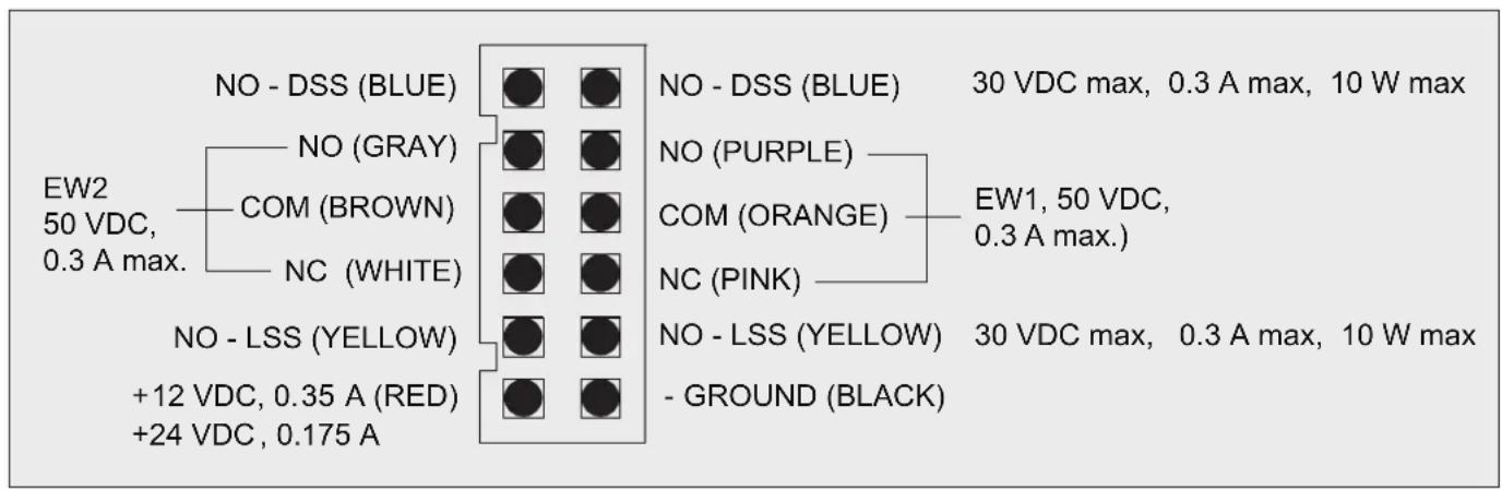
The MEM2400LED lock is provided with a number of unique monitoring features for either local or remote indication:
i. Door Status Signal (DSS) 1 set of normally open contacts (N/O -- blue).
ii. Lock Status Signal (LSS) 1 set of normally open contacts (N/O -- yellow).
iii. Early Warning (EW) x 2. 2 sets of single throw double pole switches.
EW1: (N/O -- purple); (COM -- orange); (N/C -- pink).
EW2: (N/O -- gray); (COM -- brown); (N/C -- white).
Functions
The MEM2400LED Mechanical Electromagnetic Lock operates on either 12 or 24 VDC. It is factory set on 24VDC and can be changed over to 12VDC by voltage jumper selection. When power is applied to the lock and the door is in the closed position the Armature Plate is magnetically attracted to the MEM device and both the DSS & LSS switches change status to NC.
When pressure is applied to the door in an attempt to open it unauthorised, the MEM Lock provides the patented local or remote “Early Warning” (EW) security alarm indication.
Power Supply
The operating switch or controlling contacts must be installed directly from the power source across the MEM Lock. The DC output of the power supply must NOT be connected to earth but floating to prevent shock and possible damage to the unit.
Wiring and Power Input
NOTE:
Ensure that wiring is connected correctly before supplying power to the MEM Lock to prevent damage to the unit.
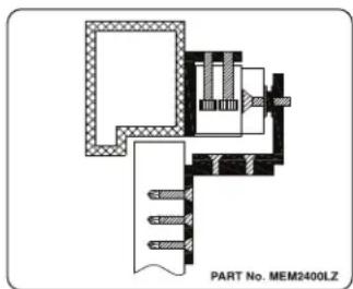
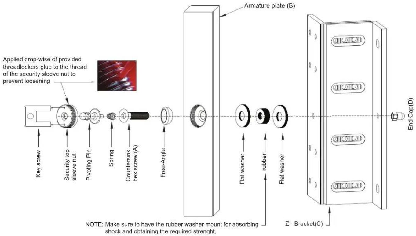
Installation diagram
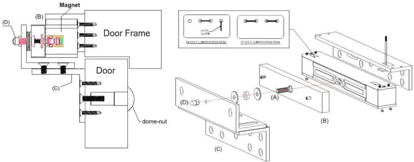
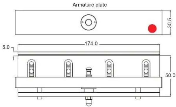
Armature Plate Installation Instructions
The Armature plate (B) is screw fixed onto and through the Z-Bracket (C), with the countersunk hex screw (A). The Armature plate must remain flexible to allow surface alignment with the MEM magnet face. The MEM Lock will lose holding force without this floating alignment.
- Screw fix the Z- Bracket (C) directly to the face of the door with the self-tapping screws provided.
- Install Armature plate (B) with countersunk Allen screw (A) into and through the Z-Bracket (C).
Ensure that the 2 flat washers and 1 rubber washer are in place and tighten the screw into the tapped hole of the Z-Bracket(C).
Note: The Armature plate, when tightened, must remain flexible and be allowed to float as mentioned above.
- Install the End Cap(D) onto the Countersunk hex screw (A).
MEM2400 LED Output and Indication Status Table
| Serial number | Condition | DSS EW1 | EW2 LSS | Indication on Lock (LED) | ||
| 1 | Power OFF Door Open |  |  OR OR |  BR BR |  TEL TEL | Power Off No LED Indication |
| 2 | Power OFF Door Closed |  |  |  |  | Power Off No LED Indication |
| 3 | Power On Door Open |  |  |  | [0976W] | Red LED ON |
| 4 | Power On Door Closed |  | [SCKW] |  |  | Green LED ON |
| 5 | Power On Door Closed & Tampered |  |  | [WZZS] |  | Green LED ON |
Light feature
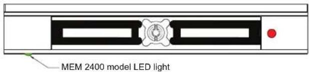
natural_image
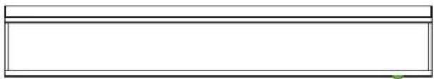
Simple rectangular outline with a small green dot at the bottom right corner (no text or symbols)Installation dimension
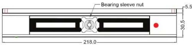
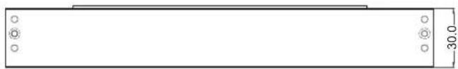
natural_image
Pure technical drawing of a rectangular plate with mounting holes and dimension label (no text or symbols beyond measurement)Important Safety Precaution
Using the template provided, secure the MEM2400LED Lock firmly on the door frame with the provided screws and have it checked periodically for any possible screw loosening.
Maintenance
Contacting surfaces of the Mechanical Electromagnetic Lock and Armature Plate must be kept free of contaminating materials. Surfaces should be cleaned periodically with a non-abrasive cleaner. Do not spray the MEM Lock or Armature Plate surface with any lacquer chemicals. This will cause serious problems with the release of the Armature plate from the Mechanical Electromagnetic Lock leading to possible serious safety problems.
Trouble Shooting
| PROBLEM POSSIBLE CAUSE SOLUTION | ||
| Door will not lock | Incorrect voltage. | Check voltage jumper setting. |
| No DC voltage to lock. | Check power and loose wiring. | |
| Incorrect wiring connection. | Check wiring, refer to wiring instruction. | |
| Security top sleeve nut higher than magnet surface. | Screw fix the security top sleeve nut level with surface with the provided key screw and apply thread-locker-glue. | |
| Too much back pressure when power is off | Back pressure exerted on the MEM lock not allowing the magnetic lock to retract back to its original position. | Avoid applying continuous pressure on the door when closed. Realign the door. |
Accessories and Applications
Adjustable L&Z Bracket is part of the MEM2400LED Kit.