RCI 4 - Lock Dormakaba - Free user manual and instructions
Find the device manual for free RCI 4 Dormakaba in PDF.


| Product Type | Lock |
| Brand | Dormakaba |
| Model | RCI 4 |
| Material | Steel and zinc alloy |
| Dimensions (H x W x D) | 115 x 70 x 20 mm |
| Weight | 0.8 kg |
| Power Supply | None (mechanical) |
| Locking Mechanism | Deadbolt with key |
| Key Type | Standard cylinder key |
| Security Rating | EN 12209 Grade 3 |
| Door Thickness Compatibility | 35-55 mm |
| Backset | 60 mm |
| Faceplate Dimensions | 24 x 235 mm |
| Main Functions | Locking and unlocking from inside/outside with key |
| Handing | Reversible (left/right) |
| Maintenance | Clean with damp cloth, lubricate lock mechanism annually |
| Spare Parts | Available from Dormakaba (keys, cylinders, springs) |
| Reparability | Modular design, parts replaceable |
| Certification | CE, Fire rated (optional) |
| Warranty | 2 years |
Frequently Asked Questions - RCI 4 Dormakaba
User questions about RCI 4 Dormakaba
0 question about this device. Answer the ones you know or ask your own.
Ask a new question about this device
Download the instructions for your Lock in PDF format for free! Find your manual RCI 4 - Dormakaba and take your electronic device back in hand. On this page are published all the documents necessary for the use of your device. RCI 4 by Dormakaba.
USER MANUAL RCI 4 Dormakaba
- Determine the vertical centerline of the door lock face and the horizontal centerline of the latch.
IMPORTANT: When determining the horizontal centerline observe the following:
FOR MORTISE LOCKS: Align the angled ramps of the lip bracket with the deadlock trigger of the mortise latch.
FOR CYLINDRICAL LOCKS: Align the center of the latch with the center of the strike opening.** - Transfer both the horizontal and vertical centerlines to the doorframe.**
- Prepare the doorframe for cutting as per the appropriate drawing.
-
If required, install "no weld" mounting brackets as per the instructions on page 3.
-
Attach the strike insert (coil unit or "motor") to the lip bracket with the small machine screws provided. (M4 x 9.5mm)
- Attach the strike faceplate to the lip bracket with machine screws (M4 x 9.5mm) provided. (It may be desirable to leave these screws slightly loose to facilitate insertion into the doorframe.)
- Connect the incoming wiring from the power supply to the terminal screws on the strike insert. RCI door strikes are not polarity sensitive although be certain to observe proper polarity if a suppression diode is required for access control applications.
- Install the door strike in the doorframe using the screws provided.
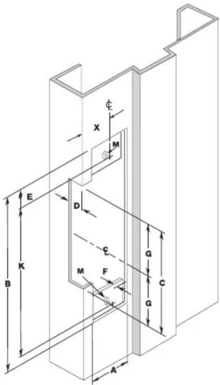
RCI 7104, 7304 Aluminum Frames, 1-1/2" D
RCI 4104, 4304 Aluminum Frames, 1-1/2" D
Any modular A41, A43, A71 or A73 with B4704 faceplate
| MEASUREMENT | FRACTIONAL INCHES | DECIMAL INCHES | METRIC mm |
| A | 1-1/4 | 1.250 | 31.75 |
| B | 4-7/8 | 4.875 | 123.83 |
| C | 3-3/8 | 3.375 | 85.73 |
| D | 7/8 | .875 | 22.23 |
| E | 3/8 | .375 | 9.53 |
| F | 18 * .125^* | 3.18^* | |
| G 1-11/16 | 1.688 | 42.86 | |
| X | Vertical Centerline of Door** | ||
| R | 5/32 | .156 | 3.97 |
| K | 4-1/8 | 4.125 | 104.78 |
| M | 12-24 | — | — |

RCI 7105, 7305 Aluminum & Wood Frames, 1-1/2" D
RCI 4105, 4305 Aluminum & Wood Frames, 1-1/2" D Any modular A41, A43, A71 or A73 with B4705 faceplate
| MEASUREMENT | FRACTIONAL INCHES | DECIMAL INCHES | METRIC mm |
| A | 1-1/8 | 1.125 | 28.58 |
| B | 5-7/8 | 5.875 | 149.23 |
| C | 3-3/8 | 3.375 | 85.73 |
| D | 7/8 | .875 | 22.23 |
| E | 1/4 | .250 | 6.35 |
| F | 1/8* .1 | 25* 3.13* | |
| G | 1-11/16 | 1.687 | 42.86 |
| X | Vertical Centerline of Door** | ||
| R | 5/32 | .156 | 3.97 |
| K | 5-3/8 | 5.375 | 136.53 |
| M | 12-24 | — | — |

NOTE: Specifications subject to change without notice.
* Dimension F is measured from face of mounting tab to face of frame.
**Dimension X on the drawing is determined by the vertical centerline of the door. If the latch incorporates a deadlocking pin additional steps will be necessary to ensure proper operation of the deadlocking pin. Measure the thickness of the deadlocking pin and add this thickness to Dimension X to relocate the vertical centerline an appropriate distance on the frame.
For wood frame door installations, substitute #12 wood screws for dimension M.
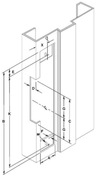
RCI 7114, 7314 Hollow Metal Frames, 1-1/2" D
RCI 4114, 4314 Hollow Metal Frames, 1-1/2" D
Any modular A41, A43, A71 or A73 with B4714 faceplate
| MEASUREMENT | FRACTIONAL INCHES | DECIMAL INCHES | METRIC mm |
| A | 1-1/4 | 1.250 | 31.75 |
| B | 4-7/8 | 4.875 | 123.83 |
| C | 3-3/8 | 3.375 | 85.73 |
| D | 7/8 | .875 | 22.23 |
| E | 3/8 | .375 | 9.53 |
| F | 1/8* .125 | 3.18* | |
| G | 1-11/16 | 1.687 | 42.86 |
| X | Vertical Centerline of Door** | ||
| K | 4-1/8 | 4.125 | 104.78 |
| M | 12-24 | — | — |
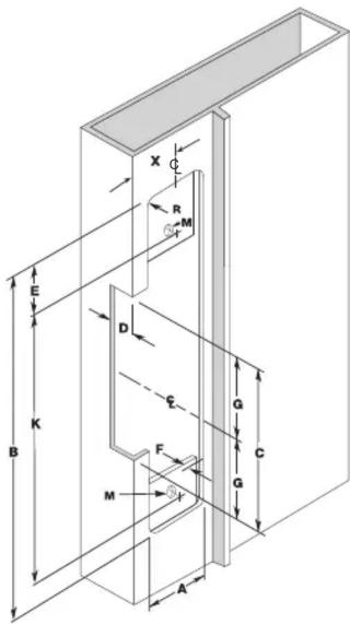
RCI 7107, 7307 Aluminum & Wood Frames, 1-1/2" D
RCI 4107, 4307 Aluminum Frames, 1-1/2" D
Any modular A41, A43, A71 or A73 with B4707 faceplate
| MEASUREMENT | FRACTIONAL INCHES | DECIMAL INCHES | METRIC mm |
| A | 1-1/4 | 1.250 | 31.75 |
| B | 6-7/8 | 6.875 | 174.64 |
| C | 3-3/8 | 3.375 | 85.73 |
| D | 7/8 | .875 | 22.23 |
| E | 3/8 | .375 | 9.53 |
| F | 1/8* .125 | 3.18* | |
| G | 1-11/16 | 1.687 | 42.86 |
| X | Vertical Centerline of Door** | ||
| R | 5/32 | .156 | 3.97 |
| K | 6-1/8 6 | 125 155 | .58 |
| M | 12-24 | — | — |
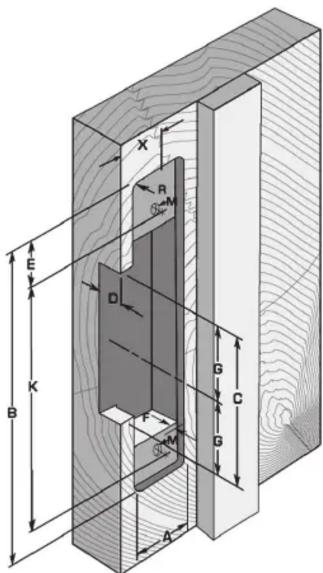
RCI 7108, 7308 Aluminum & Wood Frames, 1-1/2" D
RCI 4108, 4308 Aluminum & Wood Frames, 1-1/2" D
Any modular A41, A43, A71 or A73 with B4708 faceplate
| MEASUREMENT | FRACTIONAL INCHES | DECIMAL INCHES | METRIC mm |
| A | 1-7/16 | 1.438 | 36.51 |
| B | 7-15/16 | 7.938 | 201.61 |
| C | 3-3/8 | 3.375 | 85.73 |
| D | 7/8 | .875 | 22.23 |
| E | 1/4 | .250 | 6.35 |
| F | 1/8* .125 | 3.18* | |
| G | 1-11/16 | 1.687 | 42.86 |
| X | Vertical Centerline of Door** | ||
| R | 5/32 | .156 | 3.97 |
| K | 7-7/16 | 7.438 | 188.9 |
| M | 12-24 | — | — |
RCI 7119, 7319 Hollow Metal & Wood Frames, 1-1/2" D
RCI 4119, 4319 Hollow Metal & Wood Frames, 1-1/2" D Not available in modular program
| MEASUREMENT | FRACTIONAL INCHES | DECIMAL INCHES | METRIC mm |
| A | 1-3/8 | 1.375 | 34.93 |
| B | 9 9.0 | 22 | 8.60 |
| C | 3-3/4 | 3.75 | 95.25 |
| D | 1-1/2 | 1.50 | 38.10 |
| E | 5/16 | .312 | 7.94 |
| F | 1/8* .125 | 3.18* | |
| G | 1-7/8 | 1.875 | 47.63 |
| X | Vertical Centerline of Door** | ||
| K | 8-3/8 | 8.375 | 212.73 |
| M | 12-24 | — | — |
NOTE: Specifications subject to change without notice.
* Dimension F is measured from face of mounting tab to face of frame.
**Dimension X on the drawing is determined by the vertical centerline of the door. If the latch incorporates a deadlocking pin additional steps will be necessary to ensure proper operation of the deadlocking pin. Measure the thickness of the deadlocking pin and add this thickness to Dimension X to relocate the vertical centerline an appropriate distance on the frame.
For wood frame door installations, substitute #12 wood screws for dimension M.
When installing an electric strike on an inactive door of a set of double doors, it can be treated the same as a frame installation in most situations. For more information contact the Technical Service Department.

natural_image
Metal bracket with cutouts and mounting holes, no text or symbols visibleMounting Tab Kit Instructions
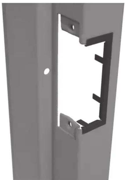
The mounting tab kit is for use with aluminum and steel frames that do not have factory installed mounting tabs for electric strike installation.
- Prepare the frame as shown in the approximate drawing. Fasten the mounting tab to the faceplate of the strike, selecting the appropriate shims for the installation.
- Using the assembled strike and tabs as a template, place against the frame and mark the mounting hole locations that suit best. Remove and drill two 3/16" holes in frame for each mounting tab and countersink the frame.
- Remove the tabs from the faceplate and install in the frame using the 12-24 x 3/8" machine screws supplied. Tabs are zinc plated and drilled and tapped for this purpose.
- Make final electrical connections per wiring instructions and mount strike to the tabs with the 12-24 x 3/8" machine screws.
Trim Plate Instructions
- Position the Trim Plate on the frame cut-out to verify fit and coverage.
- Adjust cut-out if required.
- Bend the four tabs to hold the Trim Plate onto the frame.
- For a tighter fit, pre-bend the two long flange tabs before sliding onto the frame where space allows.
- Secure the strike to the frame as per strike installation instructions.
| SolutionPossible CausesProblem | |||
| 1. | Strike will not lock or unlock properly | No power to the strike | Using a multimeter, confirm that you have the correct output voltage at the power supply. |
| Using a multimeter, confirm that you have the correct input voltage at the strike. | |||
| Confirm that all connections are tight and secure. | |||
| Incorrect voltage used | Confirm that the insert and power supply are the proper voltage. | ||
| Strike is binding | Confirm that the strike keeper functions when the door is open. If the strike operates correctly, adjust door or strike to eliminate any backpressure. | ||
| Confirm that the strike cavity depth is compatible with the lock set. | |||
| 2. | Strike releases but won't buzz | Improper power supply | Replace the power supply with a correct voltage AC power supply. If this cannot be done, a DC piezo buzzer can be installed. |
| 3. | Strike makes a buzzing sound | Improper power supply | Replace the power supply with a correct voltage DC power supply. |
| Improper application | A strike connected to an AC power supply will buzz unless a rectifier is installed. | ||
| 4. | Strike has a burnt smell | Improper voltage | Confirm that you have the correct output voltage at the power supply. |
| Improper installation | Confirm that all connections are tight and secure. | ||
| 5. | Mortise lock not dead latching | Improper installation | Check alignment of dead latch and lip bracket ramp. |
| Door has sagged | Adjust door alignment. | ||
| 6. | Cylindrical dead latching not working | Improper installation / Door has warped | Adjust the strike horizontal adjustment. (See Installation Instructions). |
| 7. | Door won't latch Door has warped or sagged creating excessive back pressure | Re-align door in frame or replace. | |
Brand : Dormakaba
Model : RCI 4
Category : Lock