RCI YG80 - Lock Dormakaba - Free user manual and instructions
Find the device manual for free RCI YG80 Dormakaba in PDF.


| Product Type | Mortise Lock for Commercial Use |
| Brand | Dormakaba |
| Model | RCI YG80 |
| Dimensions (Overall) | Approx. 4.5 x 3.0 x 1.2 inches (backset varies) |
| Weight | Approx. 2.5 lbs |
| Power Source | Mechanical (no battery required) |
| Finish Options | Brushed Chrome, Satin Nickel, Oil Rubbed Bronze |
| Backset | 2-3/4 inches (standard) |
| Door Thickness Range | 1-3/8 to 1-3/4 inches |
| Handing | Field reversible (left/right hand) |
| Primary Function | Privacy lock with emergency release |
| Security Level | ANSI/BHMA Grade 2 |
| Key Operation | Yes, for exterior side (key override) |
| Interior Operation | Turn piece or push button to lock |
| Emergency Release | Yes, from outside with coin/screwdriver |
| Maintenance | Periodic lubrication of moving parts with graphite |
| Cleaning | Wipe with soft damp cloth; avoid abrasives |
| Repairability | Replacement parts available from Dormakaba |
| Certifications | UL listed, Fire rated for 3-hour doors |
| Warranty | Limited lifetime mechanical warranty |
Frequently Asked Questions - RCI YG80 Dormakaba
User questions about RCI YG80 Dormakaba
0 question about this device. Answer the ones you know or ask your own.
Ask a new question about this device
Download the instructions for your Lock in PDF format for free! Find your manual RCI YG80 - Dormakaba and take your electronic device back in hand. On this page are published all the documents necessary for the use of your device. RCI YG80 by Dormakaba.
USER MANUAL RCI YG80 Dormakaba
natural_image
Two black industrial sensor modules with circular components and a blue circular component, no visible text or symbols.NOTICES

Please ensure you read all instructions!
- WARNING - Live parts inside.
- WARNING - The handling and installation of this device is recommended for a professional.
- WARNING - Use of an unsuitable power supply unit may cause product failure or injury.
- WARNING - Operation of lock while submerged may cause product failure.
- WARNING - Lock surface may become hot to touch when heater is active.

This device complies with Part 15 of the FCC Rules. Operation is subject to the following two conditions:
- This device may not cause harmful interference.
- This device must accept any interference received, including interference that may cause undesired operation.
Note: This equipment has been tested and found to comply with the limits for a Class B digital device, pursuant to Part 15 of the FCC Rules. These limits are designed to provide reasonable protection against harmful interference when the equipment is operated in a residential, commercial, or industrial environment. This equipment generates, uses, and can radiate radio frequency energy and, if not installed and used in accordance with the instruction manual, may cause harmful interference to radio communications. However, there is no guarantee that interference will not occur in a particular installation.
Modifications: Any modifications made to this device that are not approved by the manufacturer may void the authority granted to the user by the FCC to operate this equipment.
Innovation, Science and Economic Development Canada ICES-003: CAN ICES-3(B)/NMB-3(B)

Please meet the following requirements of UL!
- If the unit is installed on a fire exit door the product installation shall be allowed only if accepted by a local AHJ authority having jurisdiction and shall comply with NFPA 101.
- The unit is to be connected and controlled via a UL listed 294 Access Control Unit.
- That the unit shall be installed in accordance to NFPA 70 and the Canadian electrical code CSA 22.2 along with any additional requirements imposed by the local authority of jurisdiction.
- Do not connect the unit to a receptacle controller by a switch.
- If the unit is installed in conjunction with panic hardware the lock shall be installed in a manner to not impair panic device operations.
- The unit shall be powered by a UL 294 listed power supply with a Class 2 power limited output.

In the European Union, Norway, Iceland and Liechtenstein: This symbol on the product, or in the manual and in the warranty, and/or on its packaging indicates that this product shall not be treated as household waste. Instead it should be taken to an applicable collection point for the recycling of electrical and electronic equipment.
By ensuring this product is disposed of correctly, you will help to prevent potential negative consequences to the environment and human health, which could otherwise be caused by inappropriate handling of this product.
In Countries Outside the European Union, Norway, Iceland and Liechtenstein: If you wish to dispose of this product please contact your local authorities and ask for the correct way of disposal.
© 2019 dormakaba Canada Inc. All rights reserved.
dormakaba Canada Inc. and/or dormakaba USA Inc. will not be liable for any direct, indirect, incidental or consequential loss or damage in any way related to this product. dormakaba Canada Inc. and/or dormakaba USA Inc. reserves the right to upgrade or change this product or instruction manual without prior notice. dormakaba Canada Inc. and/or dormakaba USA Inc. assumes no liability for damages incurred directly or indirectly from errors, omissions or discrepancies between the product and the manual.
For more information and contact details please visit,
www.dormakaba.us
CONTENTS
- DESCRIPTION....4
- PRODUCT UNBOXED ....4
- DIMENSIONS .... 5
3.1. Lock....5
3.2. STRIKE....5
- PRE-INSTALLATION ASSESSMENT....6
4.1.MECHANICAL 6
4.2.ELECTRICAL....6
- INSTALLATION....7
5.1.MOUNTING LOCK 7
5.2. MOUNTING STRIKE....7
5.3. CONFIGURE AND COVER 8
- CONFIGURATION....9
6.1.WIRING 9
6.2. DIP SWITCH POSITIONS....10
- OPERATION....11
7.1. OPERATION MODES ...... 11
7.2. FAILURE MODES ...... 11
7.3. HEATER MODE (REQUIRES 24VDC POWER SUPPLY) 11
- SPECIFICATIONS....12
- MAINTENANCE AND INSPECTION....12
1. DESCRIPTION
The YG80 is a low-voltage motor-driven heavy-duty lock suited for securing gates, roll up doors, shipping containers, and any other large door or entryway. The YG80 is designed to be weatherproof, low maintenance, and easy to install. It is supplied with a matching strike plate and can be installed externally or internally in a horizontal or vertical position. A solid 18mm diameter stainless steel bolt pin ensures the highest strength while a bolt pin extension of 30mm offers flexible installation.
Integrated electronics provide complete control over the lock and offer an array of features;
■ Multi-voltage input (12-24VDC)
- Ingress protection to IP67
■ Built-in heater for colder climates
■ Multiple locking / unlocking attempts
■ Multiple control methods
- Fail Safe / Fail Secure user selection with a single switch
■ Door position monitoring
■ Bolt locked and Bolt unlocked monitors
- Tamper Detection monitoring
The lock incorporates complete waterproofing to seal the lock around the bolt pin and lid, and wiring is run securely through a cable gland in the locks base.
2. PRODUCT UNBOXED
natural_image
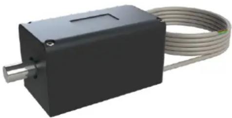
Exterior view of a black rectangular electronic device with a metallic shaft and coiled cable (no text or symbols visible)Lock (And Cable)

natural_image
3D rendering of a black mechanical bracket with mounting holes (no text or symbols)Strike
natural_image
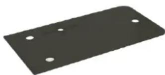
Black rectangular metal plate with four circular holes (no text or symbols)Neoprene Gasket (Optional Use)
In the box you will find the Lock, with attached 3 metre sealed cable; the Strike, with Strike Configuration Guide; and the Neoprene Gasket.
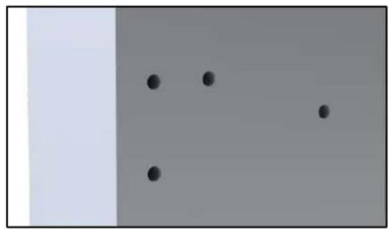
Because the YG80 can be installed onto various mounting surfaces, with different requirements for fasteners depending on the surface material, no mounting bolts are supplied. The 3 mounting holes in the lock and 4 in the strike are 8mm holes so accept M8 size bolts (or similar fasteners).
The included 1mm thick neoprene gasket provides insulation and shock protection between the YG80 and its mounting surface. By using the neoprene gasket you ensure that the heat generated when the internal heater is active (See Section 7.3) is not removed from the lock, this can occur when the mounting surface acts as a heat sink.
In freezing climates or where wind chill is a problem, it is recommended to consider covering the lock in an insulating material alongside use of the neoprene gasket. Very cold air temperatures or strong winds can pull heat off of the YG80 faster than the heater can produce, so an insulating cover will ensure the heat is retained and allow the YG80 to operate correctly and efficiently.
3. DIMENSIONS
The dimensions shown (in millimetres) are approximate and are subject to change without prior notice.
3.1. Lock

3.2. Strike


4. PRE-INSTALLATION ASSESSMENT
4.1. Mechanical
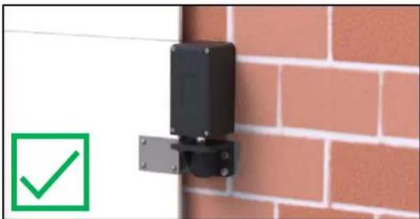
Before the lock can be installed, consider its location and orientation. The YG80 can be mounted horizontally or firing downwards vertically, however mounting it firing upwards vertically may deteriorate the bolt pin seal faster and will void warranty.
When positioning the strike, it is important to achieve a reasonable level of alignment with the bolt pin as to ensure correct locking and operation. The hole in the strike is of a larger diameter than that of the bolt pin, however installing the strike so the bolt pin goes into the hole centrally is best as it will allow for movement of the door over time. To ensure the YG80 operates properly, the lock and strike must be separated by 15mm or less.
The adjustable nature of the strike means that the supplied magnet can be inserted in the desired location for all operating conditions, meaning the strike can approach from either the right, left, top or bottom face of the lock.

natural_image
Close-up of a black mechanical component mounted on a white surface next to a brick wall, with a green checkmark icon in the corner (no text or symbols visible)Lock mounted to the ground.

natural_image
Close-up of a black mechanical component mounted on a white surface next to a yellow brick wall, with a green checkmark icon in the corner (no text or symbols on the device itself)Lock mounted to the door frame horizontally.
natural_image
Close-up of a black electrical component mounted on a brick wall, with a green checkmark icon nearby (no text or symbols on the device itself)Lock mounted to the door frame vertically down.

natural_image
Close-up of a black mechanical latch mounted on a brick wall, with a red 'X' symbol in the corner (no text or symbols on the latch itself)DO NOT mount the lock vertically up.
4.2. Electrical
After the positions of the lock and strike are determined, establish where to run the cable and also decide on what feedback is required from the lock. Please refer to wiring guide in Section 6.1.
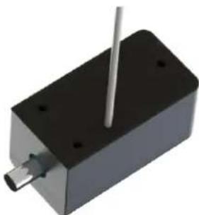
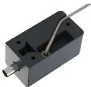
The cable is secured internally, and can either be run out of the base of the lock into the mounting surface or follow the channel in the base and be run out of the back end of the lock. If the cable is being run through the base, an additional hole is needed in the mounting surface for the cable to be pulled through.
natural_image
3D rendering of a black rectangular electronic component with a metallic rod inserted (no text or symbols visible)Cable being run out through the neoprene gasket
natural_image
3D rendering of a black rectangular electronic component with a metallic rod inserted (no text or symbols visible)Cable being tracked out the back through the channel
5. INSTALLATION
Because this lock can be installed on many different styles of doors, a generic installation instruction is provided. Ensure that the lock component is mounted to the stationary part of the door, and the strike component is mounted to the moving part of the door. Ensure you have the required mounting fasteners for your specific installation scenario. The required number of fasteners are 7 (3 for the lock component, 4 for the strike component).
5.1. Mounting Lock
5.1.1. Drill the lock mounting holes
The mounting holes in the YG80 lock component are sized for M8 fasteners.
Referring to the dimension drawings in Section 3.1; drill the holes at the marked location using appropriate tools, such as an M8 drill bit and power drill. If the cable is going to be run through the mounting surface, an 8mm hole can be used for the cable hole as well.
5.1.2. Prepare cable run
Before the lock can be mounted to the surface, the cable must be prepared. In the case of running the cable out the back end of the lock, track the cable along the channel. If the cable is going to be run straight out of the base of the lock, completely thread the cable through the prepared cable hole in the mounting surface. If the neoprene gasket is being used, thread the cable through the hole at the centre of the cross first.
Note: Ensure the cable is not pinched or severed when mounting the lock or threading through the hole. Make sure the cable doesn't rest on any sharp edges.
5.1.3. Secure the lock in position
Once the cable has been prepared, the lid of the lock must be removed to reveal the three mounting holes; this can be done by using a 4mm hex key to remove the four screws securing the lid. Once this has been done, mount the lock in place using the appropriate fasteners for the mounting surface material.
5.2. Mounting Strike
5.2.1. Drill the strike mounting holes
The mounting holes in the YG80 strike are sized for M8 fasteners.
Referring to the dimension drawings in Section 3.2; drill the holes at the marked location using appropriate tools, such as an M8 drill bit and power drill.
Note: Ensure the gap between the lock and strike (when the door is closed) does not exceed 15mm.
natural_image
Simple diagram with four black dots on a gray background, no text or symbols present
natural_image
3D rendering of an open electronic device with visible internal components and mounting brackets (no text or symbols)
natural_image
3D rendering of a black rectangular electronic device with internal circuit board and connectors (no visible text or symbols)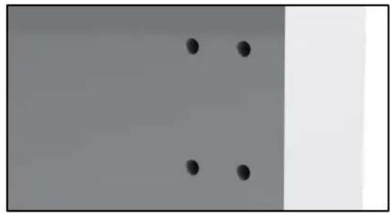
natural_image
Two black dots arranged vertically on a gray background, with a partial white rectangle on the right (no text or symbols)5.2.2. Strike Configuration
By default the strike is configured for use when the lock and strike are mounted on the same plane, so that the top of the strike and the top of the lid of the lock align when the door is closed. If the strike needs to be installed at 90 degrees to the lock, the strike will need to be reconfigured.
To configure the strike, hold the strike with the plastic strike ring face up and remove the M3 screw in the centre at the base of the hole using a #2 Phillips screwdriver. Once removed, lift out the strike ring to reveal the magnet sitting in one of the three magnet holes. This position is determined by the location of the magnet sensor in the lock, which is above the bolt pin, near the edge of the lid.
Once you have determined this location, move the magnet to the desired location, then secure the magnet by refitting the plastic strike ring and securing with the M3 screw.
5.2.3. Secure the strike in position
Once the strike has been configured for the specific installation, mount the strike in place using the appropriate fasteners for the mounting surface material.
5.3. Configure and Cover
5.3.1. Configure the lock
Connect the wires on the end of the cable to the power supply, access control system, alarm system, or entry/exit devices (Refer to Section 6.1 Wiring).
With the lid still removed, adjust the dip switches to the desired setting using a sharp tool such as a small flat head screwdriver (Refer to Section 6.2 Dip Switch Positions).
When power is supplied to the lock, after the 25 second start-up time the yellow LED to the left of the dip switches should blink indicating it has powered up
When the door is in the closed position the green LED to the left of the dip switches should light up indicating that the magnet in the strike has been detected. If this does not happen please check that the door gap is less than 15mm and the magnet is in the correct position in the strike.
Note: The micro USB port is for factory use only.
5.3.2. Cover the lock
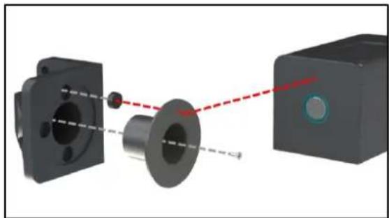
Finally screw the lid down onto the lock with a 4mm hex key. Ensure the lid is screwed down evenly and tight as otherwise the lock sealing may be compromised. Any remaining systems can now be activated, including those that take advantage of the anti-tamper monitor.
natural_image
3D mechanical assembly diagram showing a flanged component connected to a rectangular block with a red dashed line indicating alignment (no text or symbols)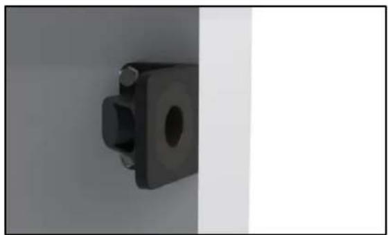
natural_image
Close-up of a black mechanical component with a circular hole and side protrusions, shown against a plain background (no text or symbols visible)

natural_image
Exterior view of a black rectangular electronic device with mounting holes (no text or symbols visible)6. CONFIGURATION
6.1. Wiring
6.1.1. Wiring Overview
The wires are part of a 3 metre sealed cable out of the YG80, the wires can be routed back to the power supply and any sensors or alarm systems. In the case of requiring a longer run, the wires can be extended as appropriate to the installation. Connect the wires as per the table below, where power and control are required for the YG80 to function, and all switch monitors are optional.
| RED | Positive + | Positive connection to DC power supply | Power (12 – 24V) |
| BLACK | Negative - | Negative connection to DC power supply | |
| BLUE | Control 1 | Switched positive control input | Control* |
| BROWN | Control 2 | Switched positive control input (Refer to Section 7.1.3) | |
| YELLOW | Bolt Unlock Switch | Normally open contact (NO), closed when the bolt pin is retracted | |
| ORANGE | Bolt Lock Switch | Normally open contact (NO), closed when the bolt pin is extended | |
| PURPLE | Door Position Switch | Normally open contact (NO), closed when the strike is aligned with the lock | |
| GREEN | Tamper Detection Switch | Normally closed contact (NC), open when the lid is removed or wires cut | |
| WHITE | Switch Common | Common contact for all the switch monitors | |
* Control 1 is required for all operating modes, however Control 2 is only required for twin wire mode.
6.1.2. Fail Safe Connection (Normal Mode)
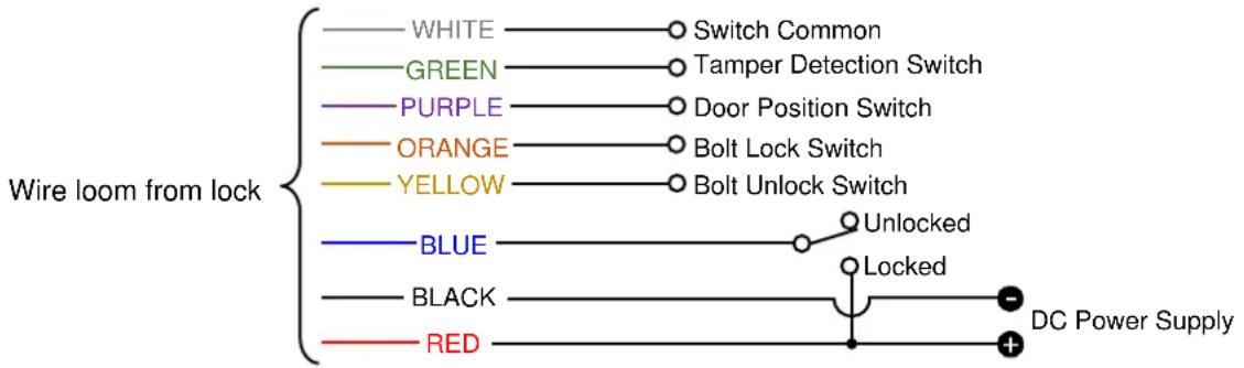
When wiring the YG80, the positive voltage is connected to RED, negative is connected to BLACK and a switched positive voltage wire connected to BLUE. In Fail Safe configuration applying voltage to the BLUE control wire signals it to lock. The lock signal in Fail Safe configuration is active high.
6.1.3. Fail Secure Connection (Normal Mode)
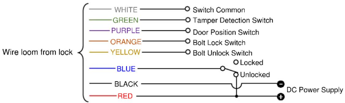
When wiring the YG80, the positive voltage is connected to RED, negative is connected to BLACK and a switched positive voltage wire connected to BLUE. In Fail Secure configuration applying voltage to the BLUE control wire signals it to unlock. The lock signal in Fail Secure configuration is active low.
flowchart
graph TD
    A["White"] --> B["Switch Common"]
    C["GREEN"] --> D["Tamper Detection Switch"]
    E["PURPLE"] --> F["Door Position Switch"]
    G["ORANGE"] --> H["Bolt Lock Switch"]
    I["YELLOW"] --> J["Bolt Unlock Switch"]
    K["BLUE"] --> L["Locked"]
    M["BLACK"] --> N["Unlocked"]
    O["RED"] --> P["DC Power Supply"]
6.1.4. Toggle Mode (And Twin Wire Mode)
When wiring the YG80, the positive voltage is connected to RED, negative is connected to BLACK and a switched positive voltage wire connected to BLUE (and BROWN for Twin Wire Mode). In Toggle Mode, applying a pulse to the BLUE control wire toggles between lock and unlock. In Twin Wire Mode, applying a pulse to the BLUE control wire triggers the YG80 to lock and applying a pulse to the BROWN control wire triggers the YG80 to unlock.

line
Wire loom from lock | Wire loom from lock | Signal | Description | | :--- | :--- | :--- | | WHITE | — | Switch Common | | GREEN | — | Tamper Detection Switch | | PURPLE | — | Door Position Switch | | ORANGE | — | Bolt Lock Switch | | YELLOW | — | Bolt Unlock Switch | | BROWN | — | Control 2 (Twin Wire Mode: Pulse Unlocks YG80) | | BLUE | — | Control 1 (Toggle Mode: Pulse Locks and Unlocks YG80) (Twin Wire Mode: Pulse Locks YG80) | | BLACK | — | DC Power Supply | | RED | — | + | The chart displays a single line representing the wire loom from lock to the right side of the chart. The legend indicates that each line corresponds to a different switch type or mode.6.2. Dip Switch Positions
The operating configuration of the YG80 controls how the lock will function and there are several settings available. There are four dip switches on the printed circuit board with three being used to configure the lock and the fourth for diagnostic purposes. The dip switches are located on the top of the printed circuit board (pictured below) and can be set as per the following table.

| DIP SWITCH # | SETTING | DESCRIPTION |
| 1 | Operation Modes | Set how the control line/s lock or unlock the YG80 (Refer to Section 7.1) |
| 2 | ||
| 3 | Failure Modes | Set whether the YG80 will lock or unlock on failure (Refer to Section 7.2) |
| 4 | Heater Mode | Set whether the heater will activate at low temperatures. Use this setting when the ambient temperature can drop below 0°C (Refer to Section 7.3) |
| 1 | 2 | |
| OFF | OFF | Normal Mode Operation |
| OFF | ON | Toggle Mode Operation |
| ON | OFF | Twin Wire Mode Operation |
| ON | ON | Diagnostic Mode Operation |
| 3 | |
| OFF | Fail Safe Mode, the YG80 will unlock on failure |
| ON | Fail Secure Mode, the YG80 will lock on failure |
| 4 | |
| OFF | Heater Off |
| ON | Heater On (Requires 24VDC to be supplied) |
| TOGGLE | Next Diagnostic Test (Diagnostic Mode Only) |
7. OPERATION
7.1. Operation Modes
7.1.1. Normal Mode
The BLUE 'Control 1' connection is used to lock and unlock the YG80 by either being connected to the supply voltage or being disconnected. The function of normal mode depends on the current failure mode setting.
When in Fail Safe mode, if power is applied to the BLUE 'Control 1' connection, and the YG80 detects the door is closed, the bolt will engage and lock the door. When power is removed, the bolt will disengage and unlock the door. When in Fail Secure mode, if power is removed from the BLUE 'Control 1' connection, and the YG80 detects the door is closed, the bolt will engage and lock the door. When power is applied, the bolt will disengage and unlock the door.
7.1.2. Toggle Mode
The BLUE 'Control 1' connection is used to lock and unlock the YG80 by applying a pulse of the supply voltage to toggle the state of the lock. This function does not depend on the failure mode setting.
If a short pulse is applied to the BLUE 'Control 1' connection the bolt will disengage and unlock the door. When a second pulse is applied to the BLUE 'Control 1' connection, and the YG80 detects the door is closed, the bolt will engage and lock the door.
7.1.3. Twin Wire Mode
The BLUE 'Control 1' connection is used to lock the YG80, and the BROWN 'Control 2' connection is used to unlock the YG80, by applying a pulse of the supply voltage. This function does not depend on the failure mode setting.
If a short pulse is applied to the BROWN 'Control 2' connection the bolt will disengage and unlock the door. When a pulse is then applied to the BLUE 'Control 1' connection, and the YG80 detects the door is closed, the bolt will engage and lock the door.
7.1.4. Diagnostic Mode
There are six tests which can be cycled through by toggling the position of the fourth dip switch on or off. The yellow LED will blink based on what test number you are on. Once testing has been completed, ensure all four of the dip switches have been returned to their original operating position.
| TEST | NAME | DESCRIPTION |
| 1 | Cycle Count | The green LED lights up if the cycle count is below 300,000 cycles |
| 2 | Motor Health | After 3 test cycles, if the LED goes solid green the motor is in good health |
| 3 | Power Supply | After 10 seconds, if the LED goes solid green the power supply is probably suitable |
| 4 | Control 1 | The green LED lights up whenever the Control 1 input is active |
| 5 | Control 2 | The green LED lights up whenever the Control 2 input is active |
| 6 | Hall Sensor | The green LED lights up whenever the strike magnet is detected |
7.2. Failure Modes
7.2.1. Fail Safe Mode
In the event of power failure, when the door is closed and the YG80 is in the locked state, the bolt pin will disengage from the strike. This ensures safe passage in emergency situations, as well as access when power is unavailable.
7.2.2. Fail Secure Mode
In the event of power failure, when the door is closed and the YG80 is in the locked state, the bolt will stay engaged with the strike. If the door is open and the YG80 cannot detect the strike, the bolt will not engage until power returns. This ensures that a lock will not disengage during power failure, keeping the access secured.
7.3. Heater Mode (Requires 24VDC Power Supply)
The heater mode allows the YG80 to be used in colder climates, where the bolt pin can become iced over. When the heater mode is enabled, the YG80 will automatically activate the heater to ensure the lock is operating above freezing conditions. The heater will self-regulate and only be active when it is needed to conserve energy. Refer to Section 2 for information about the use of the neoprene gasket for added benefits in colder climates.
8. SPECIFICATIONS
| MATERIALS | ||||
| Bolt Pin | Stainless Steel (SS304), ø18mm, 30mm extension, ø28mm receiver | |||
| Lock Body | Aluminium (A383), 150mm x 80mm x 80mm | |||
| Strike Body | Aluminium (A383), 60mm x 80mm x 80mm | |||
| MECHANICAL | ||||
| Cycle Life | 300,000 normal operations (self-declared) | |||
| Maximum Strike Gap | 15mm | |||
| Static Strength | 11240 lbf (50,000N) (self-declared) | |||
| Dynamic Strength | 150 ft·lbf (200J) (self-declared) | |||
| ELECTRICAL | ||||
| Voltage at Lock | 12 – 24VDC ±15%, maximum wire distance 98.5ft (29m) | |||
| Auto Relock | Will attempt to lock or unlock 3 times if obstructed during operation | |||
| Initial Power Up Time | 25 seconds, only after power has been removed for an extended period | |||
| Current Usage | Standby Current | 40mA@12V | 30mA@24V | 1.6A@24V with heater on |
| Maximum Current | 1.0A@12V | 0.5A@24V | 2.0A@24V with heater on | |
| Monitor Switches | 24VDC, 0.25A | |||
| CERTIFICATIONS | ||||
| UL | UL 294 | Line Security Level IStandby Power Level IAttack Level IEndurance Level IV | ||
| UL1034 – UL static and dynamic strength ratings were verified on swing door applications only | Static Strength: 1500 lbf (6673N)Dynamic Strength: 70 ft·lbf (95J)Endurance: 250,000 cycles | |||
| Environment – Suitable for indoor and outdoor use | IP67 Rated; Corrosion, 240 Hours Salt Spray, EN1670:2007, Grade 4 | |||
| Cold, -31°F (-35°C) for 4 Hours (The heater shall be active, see Section 6.2) | ||||
| Dry Heat, 150°F (66°C) for 4 Hours; Humidity, +30°C at 85% humidity | ||||
| FCC / ISED (IC) | Title 47, Part 15, Subparts A & B – Class B Device; ICES-003 – Class B Device | |||
| CE | EMC 2014/30/EU, RoHS 2011/65/EU, Directive (EU) 2015/863 | |||
9. MAINTENANCE AND INSPECTION
The YG80 has been lubricated at assembly and applying any other type of lubricant may void the warranty. With the lid removed it is important to take care when selecting the configuration or interacting with the printed circuit board. To keep the YG80 working effectively, ensure the strike hole and bolt pin are clear of debris at all times. This lock contains components that are subject to wear based on usage, doorway operation and installation; all such factors are beyond the control and measurement of the manufacturer. The lock may be vulnerable and subject to failure as a consequence of wear and as its components near the end of the period of normal usage.
It is the responsibility of the owner/end-user to:
a) Ensure that the lock is installed in accordance with the instructions set out in these guidelines.
b) Determine the suitability of this lock for the application intended and in particular when using this lock in critical applications such as on high security, safety, or emergency exit doors.
c) Regularly inspect this lock in order to assess signs of wear and tear, and determine if the operation still conforms to the instructions set out in these guidelines.
d) Regularly inspect the lock and evaluate cycle life.
e) Determine when this lock should be replaced.
- NOTICES
- Please ensure you read all instructions!
- Please meet the following requirements of UL!
- CONTENTS
- DESCRIPTION
- PRODUCT UNBOXED
- DIMENSIONS
- PRE-INSTALLATION ASSESSMENT
- Mechanical
- Electrical
- INSTALLATION
- Mounting Lock
- Drill the lock mounting holes
- Prepare cable run
- Secure the lock in position
- Mounting Strike
- Drill the strike mounting holes
- Strike Configuration
- Secure the strike in position
- Configure and Cover
- Configure the lock
- Cover the lock
- CONFIGURATION
- Wiring
- Wiring Overview
- Fail Safe Connection (Normal Mode)
- Fail Secure Connection (Normal Mode)
- Toggle Mode (And Twin Wire Mode)
- Dip Switch Positions
- OPERATION
- Operation Modes
- Normal Mode
- Toggle Mode
- Twin Wire Mode
- Diagnostic Mode
- Failure Modes
- Fail Safe Mode
- Fail Secure Mode
- Heater Mode (Requires 24VDC Power Supply)
- SPECIFICATIONS
- MAINTENANCE AND INSPECTION
Brand : Dormakaba
Model : RCI YG80
Category : Lock