
FZK 70305-0 - Tiller Fieldmann - Free user manual and instructions
Find the device manual for free FZK 70305-0 Fieldmann in PDF.


| Product Type | Rototiller (Tiller) |
| Brand | Fieldmann |
| Model | FZK 70305-0 |
| Engine Type | 4-Stroke, Gasoline |
| Engine Displacement | 196 cc |
| Power Output | 5.5 HP (4.1 kW) |
| Tilling Width | 50 cm (19.7 inches) |
| Tilling Depth | Adjustable: 10-25 cm (3.9-9.8 inches) |
| Number of Tines | 4 pairs (8 tines) |
| Transmission | Single forward gear |
| Starting System | Recoil start |
| Fuel Tank Capacity | 1.2 L (0.3 gal) |
| Weight | 32 kg (70.5 lbs) |
| Overall Dimensions (L x W x H) | 85 x 55 x 65 cm (33.5 x 21.7 x 25.6 inches) |
| Handle Type | Adjustable handles with ergonomic grip |
| Wheels | Transport wheels for easy mobility |
| Safety Features | Engine stop switch, safety guard |
| Maintenance | Oil change, air filter cleaning, spark plug check |
| Spare Parts Availability | Tines, belts, filters, spark plugs |
| Repairability | User-serviceable with manual instructions |
| Warranty | 2 years |
Frequently Asked Questions - FZK 70305-0 Fieldmann
User questions about FZK 70305-0 Fieldmann
0 question about this device. Answer the ones you know or ask your own.
Ask a new question about this device
Download the instructions for your Tiller in PDF format for free! Find your manual FZK 70305-0 - Fieldmann and take your electronic device back in hand. On this page are published all the documents necessary for the use of your device. FZK 70305-0 by Fieldmann.
USER MANUAL FZK 70305-0 Fieldmann
Home & Garden Performance

natural_image
Green and black utility tool with metal frame, no visible text or symbolsFZK 70305-0
English 3-19
Česky 21-37
Slovensky....39-55
Magyarul....57-73
Polski 75-91
CORDLESS TILLER
USER'S MANUAL
20V _LiHON
FASTPOWER
Thank you for purchasing this cordless tiller.
Before using it, please carefully read this User manual and keep it in a safe place for further use. This product was designed and built according to our high norms for reliability, ease of use and safety of operation. With proper care, it will give you many years of reliable problem-free service.
TABLE OF CONTENTS
- General safety instructions ....4
Important safety notice....4
Packaging 6
User manual....6 - Basics of work safety 7
Work clothes/work area....8
Interrupting work....8
Other risks 8 - Symbols 9
- Purpose of use....9
- Machine description ....10
- Assembly....11
- Using....15
Removing foreign objects....15 - Maintenance....15
- Storage....17
- Technical specifications....17
- Disposal....18
1. GENERAL SAFETY INSTRUCTIONS
Important safety notice
Carefully unpack the product and take care not to throw away any part of the packaging before you find all the parts of the product.
Store the product in a dry place out of reach of children.
Read all warnings and instructions. Failure to follow warnings or instructions may lead to injury by electrical shock, fire and/or serious injuries.
Before using, check that everybody that will be using the machine has read and understood these safety instructions and other information contained in this user's manual.

ATTENTION: Use appropriate hearing protection when using this machine. Under certain conditions and after a certain period of using the machine, the produced noise may cause hearing loss.
Inspection of damaged parts
Before every use, all damaged parts must be carefully inspected to determine whether they will work correctly and fulfil their function. Check the adjustment and fastening of moving parts, damaged parts, fastening elements and other conditions which may affect operation. All damaged parts must be repaired or replaced.
Do not use in a hazardous environment
Do not use the machine in rain, during a storm or in a damp or wet environment. Do not operate the machine in an environment where there are gases or in an explosive environment. The motors on these machines spark during operation and these sparks could ignite the vapours.
Keep out of the reach of children
Bystanders, children and animals must be at a safe distance.
Dress appropriately
Do not wear loose clothing and jewellery and keep long hair inside a protective mesh cap. They could become caught in the moving parts. When working outside, it is recommended to wear gloves and solid footwear.
Use safety glasses
When using this product, wear safety glasses with protective sides. In the case of a dusty environment, use a face mask or respirator.
Double insulation
The tiller is equipped with double insulation. This means that all metal parts are insulated from the electrical power supply. This is achieved by an insulating layer between the electrical and mechanical parts. Double insulation provides you with the highest possible level of safety.
Overheating protection
If the tiller is blocked by a foreign object or its motor is overloaded, a safety mechanism will automatically turn the motor off. Release the start lever and wait until the motor cools down (approximately 15 minutes) before starting the tiller again.
Disconnect the machine from the power supply if you will not be using it, if you are going to wash or repair it. Do not leave it without supervision.
Do not damage the power cord
Never carry the machine by the power cord or tug on it in order to pull it out of the power socket. Protect the power cord against heat, oil and sharp edges.
Use the machine properly
Do not use this appliance for other purposes than those for which it is intended (see chapter "Purpose of use").
Do not overestimate your abilities
Lead the tiller only at walking speed. When working, constantly maintain a firm posture and balance.
Lighting
Use the tiller only during daylight or strong artificial lighting.
Store the machine under a roof when not in use
If you are not using the tiller, place it under a roof in a dry location to which children do not have access.
Perform meticulous maintenance of the machine
For the best performance and lowest risk of injury, keep the machine clean and regularly check the extension cord and replace it when it is damaged. Keep the handles dry, clean and unstained by oil.
Pay attention
Pay attention to what you are doing. Apply common sense. Do not use the tiller if you are tired or under the influence of drugs or medication.
WARNING:: Do not use the tiller in the vicinity of underground electric or telephone cables, pipes or hoses. If the tiller hits a foreign object, immediately turn it off, wait until the blades come to a stop and check them for damage. If necessary, seek out the services of an authorised service centre. If the tiller begins to vibrate excessively, immediately turn it off and identify the cause. Vibrations usually indicate a problem.
ATTENTION: Danger of cuts! When cleaning or carrying out maintenance on the filler, please use protective gloves and take care.
Before starting any type of maintenance or repair work on the tiller, turn it off, wait until the blades come to a stop and disconnect it from the power supply.
ATTENTION: The blades will not come to a stop immediately after the tiller is turned off.
ATTENTION: Risk of injury. Keep your hands, legs and other parts of your body and clothing always well away from the rotating blades of the tiller.
Packaging
The product is packed in a package that prevents damage during transport. This packaging is a resource and can be recycled.
User manual
Before you start working with the machine, read the following safety instructions and carefully study the fundamentals for work with the machine. Get familiar with the controls and correct use of the equipment. Keep the user's manual in a safe place for easy future reference. Save the original packaging, including the internal packing material, guarantee card and proof of purchase receipt for at least the time of the guarantee. If you need to ship this machine, pack it in the original cardboard box to ensure maximum protection during shipping or transport (e.g. when moving or when you need to send this product for repair to a service centre).
NOTE: If you hand over the appliance to somebody else, do so together with this user's manual. Following the instructions in the included user's manual is a prerequisite for the proper use of the power tool. The user's manual also contains operating, maintenance, and repair instructions. The manufacturer assumes no responsibility for accidents or damages arising from failure to comply with these instructions.
2. BASICS OF WORK SAFETY
* Never use the machine if the power cable is damaged or visibly worn.
In the event that you connect the tiller using a damaged power cord to a power source and then touch the place that is uninsulated before the tiller is disconnected from the power source, you subject yourself to a risk of injury by electrical shock.
Also, never touch the blades until the machine is disconnected from the power source and until the blades completely stop.
Make sure that the extension cable never comes into contact with the blades. The blades could damage the power cable insulation and create a risk of an electric shock when a part of the body touches the exposed wire when it is live.
* Disconnect the machine from the voltage source (i.e. pull the power cable plug out of the mains power socket):
- If you need to leave the machine without supervision.
- If you are planning to carry out troubleshooting.
- Before every inspection, every cleaning or repairs.
- If you impact a foreign object when working with it.
- If the machine vibrates excessively.
RECOMMENDATION: Only connect the machine to a power source that has a residual current device (RCD) with a maximum leakage current of 30mA.
If the power cord is damaged, it must be replaced by the manufacturer or by an authorised customer service.
This machine must not be operated by persons with limited physical, sensory or mental abilities (including children). Furthermore, it must not be used by inexperienced people who do not have the technical knowledge to operate it. These people must be supervised by a competent person or instructed about the basics of work safety.
If children are moving around in the vicinity of the machine, it is necessary to watch that they do not play with the machine.
A tingling sensation in one's hands or their numbness are indications of excessive vibrations. If this happens, shorten the work cycle, take sufficiently long breaks, share the work among several people or in the event of long term use of the tiller, use special anti-vibration gloves when working.
An unavoidable associated consequence of using the tiller is that it emits noise when it is running. Therefore, only do noisy work during dedicated hours, or when this type of activity is normal. Respect quiet times and try to limit the work to the shortest possible time. We also recommend that you and the persons near the tiller wear ear protectors.
Do not use the electric tiller with damaged, deformed or worn out safety mechanisms (start safety switch, safety cover) and/or blades. To avoid incorrect balance, faulty parts and bolts must be replaced in sets without exception.
Prior to starting work, look for and remove foreign objects (for example stones, branches, etc.).
If during work you hit an obstacle or if the blades jam up then turn the electric tiller off, pull the power plug out of the socket and wait until the blades come to a stop. Then remove the obstacle. Check the electric tiller for damage and if necessary seek assistance at an authorised service centre.
Only use the electric tiller for purposes described in this user's manual.
Do not pull the tiller along a hard surface (concrete, footpaths) or up/down stairs. Do not overload the motor. Do not place any additional weight on the tiller. After you have finished using the tiller, disconnect it from the power supply and check the machine and in particular the blades for damage and if necessary seek out an authorised service centre.
Be particularly careful when walking backwards. You could stumble!
When working on a slope, always work perpendicular to the slope and maintain a safe and firm posture.
Pay increased attention when changing direction on a slope and do not work on extremely steep slopes.
* Work only under good visibility.
Work clothes/work area
* You are responsible for safety in the work area.
Make sure that there are no people (especially children) or animals in the vicinity of the work area.
Wear robust work boots and long pants to provide protection to your legs. Never use the tiller when wearing sandals or barefoot.
- Keep hands and feet away from the blades – in particular when starting the machine! Keep the extension cord away from the blades.
Acquaint yourself with the surroundings and be aware of potential risks which could be ignored due to the noise of the machine.
Never use the machine when it is raining or in a damp or wet environment. Never work in the direct vicinity of swimming pools and garden ponds.
Interrupting work
Never leave the electric tiller in the work area without supervision.
When you interrupt work, always leave the electric tiller in a safe location and disconnect it from the power supply.
When moving the tiller from one work area to another, turn it off and wait for the blades to come to a stop. Disconnect the power cord.
Other risks
Despite the fact that our products are designed to meet the valid technical norms and safety directives in force, there still remain certain risks to the user associated with the operation of the machine:
- Stones and other fragments may fly out of the area of the blades.
- If the operator of the machine fails to use hearing protection, they risk subsequent deafness.
- Finger injury during blade maintenance.
• Inhalation of dust particles created when working with the tiller.
• Electrical shock when uninsulated parts are touched.
3. SYMBOLS
 | Warning:Read the user's manual! |
 | Do not use in rain or in wet conditions! |
 | Other people must remain at a safe distance! |
 | Rotating parts! The blades of the tiller stop only some time after the motor is shut off. |
 | In accordance with the basic safety standards of European directives in force. |
 | This machine is protected by double insulation and so it is not necessary to use a grounding wire.Always check that the voltage in the grid corresponds to the voltage on the rating label. |
 | Use hearing protection!Use eye protection!Use respiratory tract protection! |
4. PURPOSE OF USE
The FIELDMANN cordless tiller is designed for breaking up larger lumps of soil and hardened chunks of soil on small to medium size horticultural areas, home gardens and garden allotments. It is not intended for use on public fields, in parks, sports centres, on roads, in agriculture or forestry.
The cordless tiller must not be used to smash stones or for ploughing up grass areas!
Following these instruction is a prerequisite for the correct use of the cordless tiller.
5. MACHINE DESCRIPTION

A Main Unit
This is the main part of the machine.
B Lower Bars
The lowers bars connect to the main unit.
C Handle Bars
You must hold these with both hands when in use.
D Middle Bar
The middle bar connects to the lowers bars.
E Tine Blades
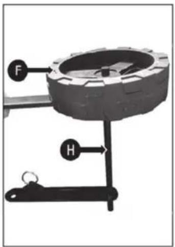
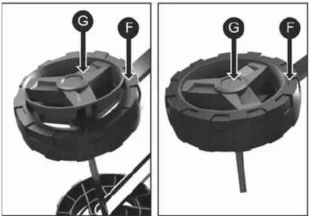
F 2 × Wheels
These attach onto the wheel axle.
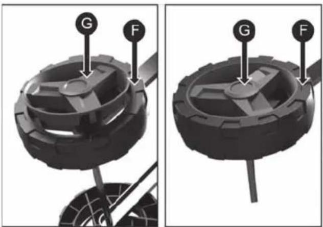
G 2 × Wheel Covers
These slot onto the wheels after you have attached them onto the wheel axle.
H Wheel Axle
Assemble the wheels onto this.
H1 Wheel Axle Bracket
This attaches to the lower bars. There is a wheel height adjuster pin which allows you to choose from two positions. You can choose from the working position (the wheels are up from the ground and the transport position (the wheels are on the ground).
1 2 × Washers For The Wheels
These are part of the wheel assembly.
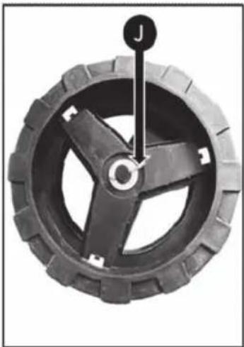
J 2 × Spirit Pins
These are part of the wheel assembly.
K Cable Clips
These keep the cable secure and fight to the machine.
L 4 × Wing Nuts
These secure the bars together. You can loosen them to fold the handlebar down for storage.
M 4 × Bolls
These secure the bars together.
N Upper Bar:
This connects to the middle bar.
O 2 × Bolts To Attach Wheel Axle To Machine
These secure the wheel axle onto the lower bars.
P 2 × Spacers
These slot onto the bolts (O).
Q 2 × Washers
These are part of attaching the wheel axle onto the lower bars.
R 2 × Nuts
Use these to secure the wheel axle onto the lower bars.
S 1 × Washer
This is part of attaching the wheel axle to the right-hand lower bar (if stood behind the handlebars).
W Wheel Height Adjuster Pin
Use this pin to select a position for the wheels (transport position or working position).
6. ASSEMBLY
There are 6 steps to the assembly:
STEP 1. Assemble The Wheels
STEP 4. Attach The upper Bar
STEP 2. Attach The Wheels
STEP 5. Attach The Cable Clips
STEP 3. Attach The Middle Bar
STEP 6. Cable Holder On Handle
STEP 1: Assemble The Wheels
- Place the wheel (F) on the axle (H).
- Place a washer (I) over the axle on top of the wheel.

natural_image
Mechanical component diagram showing a wheel with three blades and labeled parts (F, I), no readable text or symbols present.STEP 1: Assemble The Wheels (Continued)
- Place a split pin (J) through the axle hole. You must spread the split pin after inserting it. This will stop the wheel from falling off.
natural_image
Close-up of a black tire with a yellow label 'J' on top, showing no text or symbols on the tire itself.
natural_image
Close-up of a mechanical component with a knob and mounting base, no visible text or symbols-
Fit a wheel cover (G) onto the wheel (F) and clip it into place. You must line up the tabs on the wheel cover into the slots on the wheel.
-
Do this for both wheels.
natural_image
Two views of a mechanical component with labeled parts (G and F), no text or symbols present.STEP 2: Attach The Wheels
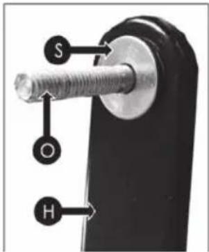
- Place the spacer (P) onto the bolt (O). Then insert the bolt through the hole on the wheel axle bracket (H1). Make sure the washer fits inside the hole as shown.
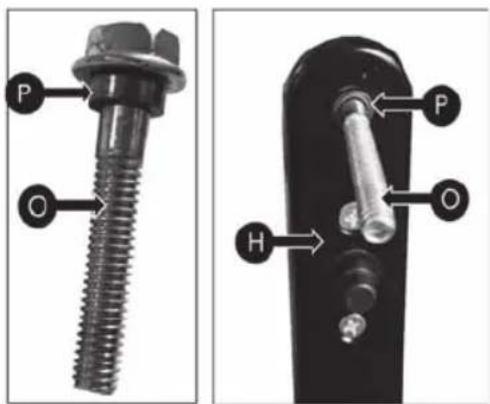
- Right-hand side (opposite the wheel height adjuster pin) - Place the washer (S) onto the bolt (O) before inserting the bolt through the hole on the lower handlebar. Left-hand side (next to the wheel height adjuster pin) - There is no need to add a washer to this side. Push the bolt through the hole on the lower handlebar.
STEP 3: Attach The Middle Bar
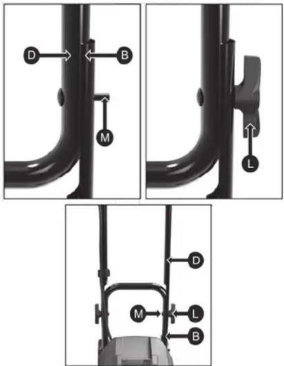
- Connect the middle bar (D) to the lower bars (B) using the wing nut (L) and bolt (M).
STEP 4: Attach The Upper Bar
- Connect the upper bar (N) to the middle bar (D) using the wing nut (L) and bolt: (M).

STEP 5: Attach The Cable Clips
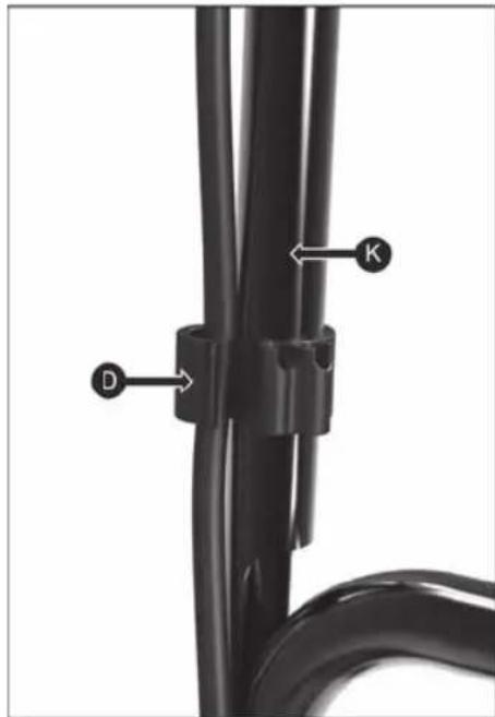
- Attach the cable onto the right-hand handlebar (D) using the cable clips (K) provided. This will keep the cable secure and tight to the machine.
natural_image
Close-up of a black cable with labeled connectors (D and K) and a coiled wire, no text or symbols present.STEP 6: Cable Holder On Handle
Make sure the machine is disconnected from power before you do this. If the machine is plugged in, you may accidentally press the trigger.
This holds the cable in place while in use and prevents strain on the cable.
- Make a small loop in the power cable (Y).
- Put the loop through the hole in the handle and on to the hook (U).
- Slowly pull the loop to remove slack.

natural_image
Two black mechanical clamps with labeled parts, shown from different angles (no text or symbols visible)7. USING
To prepare a garden bed for sowing, it is recommended to use on of the following patterns:
Loosening pattern A – Travel over the loosened area twice, the second time in cross direction to the first run, see fig.11.
Loosening pattern B – Travel over the loosened area twice, the second time overlap the first run, see fig. 11. Before use, remove all visible stones or other foreign objects.
Fig. 11

natural_image
Two schematic diagrams of coiled pipes labeled A and B, showing different flow directions (no text or symbols beyond labels)ATTENTION: Before moving the tiller from one area to another, turn the motor off and wait until the blades stop rotating. Be careful that the blades do not touch the ground while the tiller is being moved. The blades and the machine itself may be damaged even when the motor is turned off.
Removing foreign objects
During operation a stone or root may become stuck in the blades or high grass or weeds may become tangled around the shaft. To clean the blades or the shaft, first release the starting lever, wait until the blades come to a complete stop and disconnect the tiller from the power supply. Release or remove foreign objects from the blades or the shaft. To make the removal of tall grass of weeds easier, remove one or several of the blades.
8. MAINTENANCE
Disconnect the power source before performing maintenance. While performing maintenance use protective gloves.
Before every use, check that the extension cord exhibits no signs of damage or ageing. Replace the power cord if it is frayed or otherwise damaged. Check the condition of the blades and ensure that all threaded connections are pulled tight. If the blades are blunt, sharpen or replace them. For support, call an authorised service centre.
Only replace worn out or damaged parts with original spare parts. Parts from a different tiller/cultivator may not necessarily be compatible, which may result in a dangerous situation.
Check that all safety mechanisms are safe and in good condition. Repair or replace it if necessary. Lubricate the blades and shaft once per season. Before putting the tiller away at the end of the season, check that it is not damaged. Repair or replace damaged parts.

ATTENTION: Clean the tiller after every use. Neglecting proper cleaning may result in damage to the tiller or a reduction in its performance. Clean the bottom motor bearer plate and the blade cover with a brush and a soft wiping cloth dipped in a soap and water solution.
Never use a hose with water to clean the tiller! Never wash the tiller under running water, in particular with pressurised water.
If you want to remove soil and dirt from the gearbox and blades, use a stiff brush or a dampened cloth. Clean the holes on the motor cover and remove all grass and dirt remains. After cleaning the blades and shaft, immediately wipe them dry and apply a thin layer of oil to prevent corrosion.
Installing and removing the blades
For this task, we recommend that you contact an authorised service centre.
Worn out blades provide only a low level of performance and overload the motor.
Check the blades before each use. Sharpen or replace the blade if necessary. For support, contact an authorised service centre.

WARNING:: Injuries may occur when working on the blades. Use protective gloves.
To remove the blades from the shaft (fig. 12), screw out the hex bolt M8 x 40 from the shaft. Take the blades off the shaft. To install the blades, proceed in reverse order.
Fig. 12

9. STORAGE
ATTENTION: Risk of fire! The gearbox may be very hot both during and after use. Store the tiller at a safe distance from fuels, oils, Vaseline and gasses.
Thoroughly clean the entire machine and its accessories.
Store it out of reach of children in a stable safe position in a cool dry location, avoid both excessively high and excessively low temperatures. Protect it against the exposure to direct sunlight. If possible, store it in the dark. Do not store in plastic bags to prevent the accumulation of moisture.
At the end of every season, perform a general inspection of the machine and remove any deposits that may have accumulated. At the start of every season, make sure that you have checked the condition of the machine. If repairs are necessary, please contact one of our service centres (address is on the warranty card).
Store the tiller in a clean dry location to which children do not have access.
For long term storage, ensure that the tiller is protected against corrosion and frost.
At the end of a season or if you will not be using the tiller for longer than a month, wipe all metal surfaces with a cloth dipped in oil or spray it with a thin layer of oil to protect it from corrosion. Fold down the handle and store the tiller in a suitable location.
10. TECHNICAL SPECIFICATIONS
Charger Voltage: 100-240V/50-60HZ
Rated Voltage: 40 V (2 x 20V Li-ion battery)
No-load Speed: 180rpm
Working Width: 360mm
Working Depth: 220mm
Blade: 4*4pcs
11. DISPOSAL
Instructions and information about the handling of used packaging
Dispose of used packaging material at a site designated for waste in your municipality.

The appliance and its accessories are manufactured from various materials, e.g. metal and plastic. Take damaged parts to a recycling centre. Inquire at the relevant government department.

This appliance meets all the basic requirements of the EU directives.
Changes in the text, design and technical specifications may be made without prior notice and we reserve the right to make these changes.
User manual in the original language.
FAST®
FAST ČR, a.s.
U Sanitasu 1621, 251 01 Říčany, Czech Republic
tel.: +420 323 204 111, fax: +420 323 204 110
EU DECLARATION OF CONFORMITY
Product / brand: Cordless Motor Hoe / FIELDMANN
Type / model: FZK 70305-0 as factory model WR8801-W-S-360H1
DC 40V (2x 20V battery powered), working width 360mm
L_PA = 77,5dB(A),L_WA = 91,6dB(A)
Manufacturer: FAST ČR, a.s.
U Sanitasu 1621, 251 01 Říčany, Czech Republic
VAT no: CZ24777749
This declaration of conformity is issued under the sole responsibility of the manufacturer.
The object of the declaration described above is in conformity with the relevant Union harmonization legislation:
Directive MD 2006/42/EC Directive EMC 2014/30/EU
Directive NEOE 2000/14/EC Directive RoHS 2011/65/EU
The relevant harmonized standards and the other technical specifications:
EN ISO 12100:2010 EN 60335-1:2012+A11+A13+A1+A14+A2
EN 709:1997+A4 EN 6233:2008
EN 55014-1:2017+A11 EN 55014-2:2015
CE
Place of issuance: Prague
Date of issuance: 13.06.2022
Name: Petr Uher - Responsible Person
Signature:
FAST FAST CR, a.s.
U Sanitásu 1621,251 01 Ričany
tel:+420323204111
ICO:247 77 249, DIC: CZ 247 77 749
AKUMULÁTOROVÝ KULTIVÁTOR
NÁVOD K OBSLUZE
20V _LI-ION
FASTPOWER
A Hlavní jednotka
natural_image
Mechanical component diagram showing a wheel with three blades and labeled parts (F, I), no readable text or symbols beyond labels.natural_image
Close-up of a black tire with a wooden handle and a small circular component labeled 'J' (no text or symbols on the tire itself)
natural_image
Close-up of a mechanical component with a circular arrow pointing to a specific part (no visible text or symbols)natural_image
Close-up of a black bicycle handle with a vertical arrow labeled 'L' pointing to the handle (no text or symbols beyond the label)
natural_image
Mechanical device with ladder and support bracket (no visible text or symbols)natural_image
Close-up of a black cable with labeled connectors (D and K) and a coiled wire, no text or symbols present.KROK 6: Držák kabelu na rukojeti
natural_image
Two black mechanical clamps with labeled parts, shown from different angles (no text or symbols visible)7. POUŽITÍ
natural_image
Two schematic diagrams of coiled pipes labeled A and B, showing different flow directions (no text or symbols beyond labels)U Sanitasu 1621, 251 01 Říčany, Czech Republic
tel.: +420 323 204 111, fax: +420 323 204 110
EU PROHLÁŠENÍ O SHODĚ
U Sanitasu 1621, 251 01 Říčany, Czech Republic
VAT no: CZ24777749
A Hlavná jednotka
natural_image
Mechanical component diagram showing a wheel with three blades and labeled parts (F, I), no readable text or symbols beyond labels.natural_image
Close-up of a black tire with a yellow label 'J' on top, showing no text or symbols on the tire itself.
natural_image
Close-up of a mechanical component with a labeled arrow pointing to a feature, no visible text or symbols.-
Nasadte kryt kolesa (G) na koleso (F) a zaklapnite na miesto. Výčnelky na kryte kolesa musia byť zarovnané s drážkami v kolese.
-
Toto vykonajte na oboch kolesách.
KROK 2: Upevnenie kolies
KROK 4: Upevnenie hornej tyče
natural_image
Close-up of a black cable with labeled connectors (D and K) and a coiled wire, no text or symbols present.KROK 6: Držiak kábla na rukováti
natural_image
Two black mechanical clamps with labeled parts, shown from different angles (no text or symbols present)7. POUŽITIE
natural_image
Two schematic diagrams of coiled pipes labeled A and B, showing different flow directions (no text or symbols beyond labels)U Sanitasu 1621, 251 01 Říčany, Czech Republic
tel.: +420 323 204 111, fax: +420 323 204 110
EU VYHLASENIE O ZHODE
U Sanitasu 1621, 251 01 Říčany, Czech Republic
VAT no: CZ24777749
natural_image
Mechanical component diagram showing a wheel with three blades and labeled parts (I, F), no readable text or symbols beyond labels.natural_image
Close-up of a black tire with a wooden handle and a small circular mark labeled 'J' (no text or symbols on the tire itself)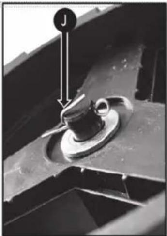
natural_image
Close-up of a mechanical component with a labeled arrow pointing to a feature, no visible text or symbols.natural_image
Close-up of a black cable with labeled connectors (D and K) and connecting rod, no text or symbols present.natural_image
Two black mechanical devices with labeled parts, shown from different angles (no text or symbols visible)7. HASZNÁLAT
natural_image
Two schematic diagrams of coiled pipes labeled A and B, showing different flow directions (no text or symbols beyond labels)U Sanitasu 1621, 251 01 Ríčany, Czech Republic
tel.: +420 323 204 111, fax: +420 323 204 110
MEGFELELŐSÉGI NYILATKOZAT
Típus / modell: FZK 70305-0 as factory model WR8801-W-S-360H1 DC 40V (2x 20V battery powered), working width 360mm LPA = 77,5 dB(A), LWA = 91,6 dB(A)
Gyártó: FAST ČR, a.s. U Sanitasu 1621, 251 01 Říčany, Czech Republic VAT no: CZ24777749
Directive MD 2006/42/EC Directive EMC 2014/30/EU
Directive NEOE 2000/14/EC Directive RoHS 2011/65/EU
és szabványoknak:
EN ISO 12100:2010 EN 60335-1:2012+A11+A13+A1+A14+A2
EN 709:1997+A4 EN 6233:2008
EN 55014-1:2017+A11 EN 55014-2:2015

Kiadva: Prágában
Név: Petr Uher - Responsible Person
dátum: 13.6.2022
natural_image
Mechanical component diagram showing a wheel with three blades and labeled parts (I, F), no readable text or symbols beyond labels.natural_image
Close-up of a black tire with a wooden handle and a small circular component labeled 'J' (no text or symbols on the tire itself)
natural_image
Close-up of a mechanical component with a circular arrow and label 'J' pointing to a feature (no readable text or symbols beyond the label)natural_image
Close-up of a black cable with labeled connectors (D and K) and connecting rod, no text or symbols present.natural_image
Two black mechanical devices with labeled parts, shown from different angles (no text or symbols visible)7. UŻYTKOWANIE
natural_image
Two schematic diagrams of coiled pipes labeled A and B, showing different flow directions (no text or symbols beyond labels)FZK 70305-0 as factory model WR8801-W-S-360H1 DC 40V (2x 20V battery powered), working width 360mm LPA = 77,5 dB(A), LWA = 91,6 dB(A)
Producent:
FAST ČR, a.s. U Sanitasu 1621, 251 01 Říčany, Czech Republic VAT no: CZ24777749
Directive MD 2006/42/EC Directive EMC 2014/30/EU
Directive NEOE 2000/14/EC Directive RoHS 2011/65/EU
i norm:
EN ISO 12100:2010 EN 60335-1:2012+A11+A13+A1+A14+A2
EN 709:1997+A4 EN 6233:2008
EN 55014-1:2017+A11 EN 55014-2:2015

Home & Garden Performance
Model /Modell /Modelis:
Conditions of guarantee
This product is warranted for the period of 24 months from the adate aof purchase to the aend-user. Warranty is limited to the following conditions. Warranty is referred only to the customer goods using for common domestic use. The claim forservice can be applied either at dealer's shop where the product was bought, oraat below mentioned authorized service shops. The end-user is obligated to set up a claim immediately when the defects appeared but only till the end of warranty period. The end-user is obligated to cooperate to certify the claiming defects. Only completed and clean (according to hygienic standards) product will be accepted. In case of eligible warranty claim the warranty period will be prolonged by the period from the date of claim application till the date of taking overthe product by end-user, or the date the end-useris obligated to take it over. To obtain the service under this warranty, end-user is obligated to certify his claim with duly completed following documents: receipt, certificate of warranty, certificate of installation ...
This warranty is avoid aespecially if aapply as follows: ■ Defects which were put on sale. ■ Wear-out aor damage caused aby acommon use. ■ The aproduct awas adamaged aby aunprofessional aor wrong installation, used in contrary to the applicable instruction manual, used in contrary to legal enactment and common process of use or used for another purpose which has been designed for. ■ The product was damaged by uncared-foror insufficient maintenance. ■ The product was damaged by dirt, accident of force majeure (natural disaster, fire, flood, ... ). ■ Defects on functionality caused by low duality of signal, electromagnetic field interference etc. ■ The product was mechanically damaged (e.g. broken button, fall...). ■ Damage caused by use of unsuitable media, fillings, expendable supplies (batteries) or by unsuitable working conditions (e.g. high temperatures, high humidity, quakes,...). ■ Repair, modification or other failure action to the product by unauthorized person ■ End-user did not prove enough his right to claim (time and place of purchase). ■ Data on presented documents differs from data on products. ■ Cases when the claiming product can not be identified according to the presented documents (e.g. the serial number or the warranty seal has been damaged).
natural_image
Green and black utility tool with dual-axis blades, no visible text or symbols
FIELDMANN®
Home & Garden Performance

- CORDLESS TILLER
- USER'S MANUAL
- 20V _LiHON
- FASTPOWER
- Thank you for purchasing this cordless tiller.
- TABLE OF CONTENTS
- GENERAL SAFETY INSTRUCTIONS
- Important safety notice
- Inspection of damaged parts
- Do not use in a hazardous environment
- Keep out of the reach of children
- Dress appropriately
- Use safety glasses
- Double insulation
- Overheating protection
- Do not damage the power cord
- Use the machine properly
- Do not overestimate your abilities
- Lighting
- Store the machine under a roof when not in use
- Perform meticulous maintenance of the machine
- Pay attention
- Packaging
- User manual
- BASICS OF WORK SAFETY
- Work clothes/work area
- Interrupting work
- Other risks
- SYMBOLS
- PURPOSE OF USE
- MACHINE DESCRIPTION
- ASSEMBLY
- There are 6 steps to the assembly:
- STEP 1: Assemble The Wheels
- STEP 1: Assemble The Wheels (Continued)
- STEP 2: Attach The Wheels
- STEP 3: Attach The Middle Bar
- STEP 4: Attach The Upper Bar
- STEP 5: Attach The Cable Clips
- STEP 6: Cable Holder On Handle
- USING
- Removing foreign objects
- MAINTENANCE
- Never use a hose with water to clean the tiller! Never wash the tiller under running water, in particular with pressurised water.
- Installing and removing the blades
- STORAGE
- ATTENTION: Risk of fire! The gearbox may be very hot both during and after use. Store the tiller at a safe distance from fuels, oils, Vaseline and gasses.
- TECHNICAL SPECIFICATIONS
- DISPOSAL
- Instructions and information about the handling of used packaging
- FAST®
- EU DECLARATION OF CONFORMITY
- CE
- AKUMULÁTOROVÝ KULTIVÁTOR
- NÁVOD K OBSLUZE
- KROK 6: Držák kabelu na rukojeti
- POUŽITÍ
- EU PROHLÁŠENÍ O SHODĚ
- KROK 2: Upevnenie kolies
- KROK 4: Upevnenie hornej tyče
- KROK 6: Držiak kábla na rukováti
- POUŽITIE
- EU VYHLASENIE O ZHODE
- HASZNÁLAT
- MEGFELELŐSÉGI NYILATKOZAT
- és szabványoknak:
- UŻYTKOWANIE
- Home & Garden Performance
- Model /Modell /Modelis:
- Conditions of guarantee
- FIELDMANN®
Brand : Fieldmann
Model : FZK 70305-0
Category : Tiller