
Ultraline UVX1-FL - AV Extension KVM-TEC - Free user manual and instructions
Find the device manual for free Ultraline UVX1-FL KVM-TEC in PDF.


| Product Type | KVM Extender (local unit CPU and remote unit CON) |
| Model | 4K Ultraline UVX1/UVX1-F KVM Extender (UVX1-F fiber version) |
| Dimensions (Local Unit) | 218 x 43 x 105 mm (8.58 x 1.69 x 4.14 in) |
| Dimensions (Remote Unit) | 218 x 43 x 105 mm (8.58 x 1.69 x 4.13 in) |
| Weight (Local Unit) | 676 g (1.49 lbs) |
| Weight (Remote Unit) | 707 g (1.55 lbs) |
| Shipment Weight | 2.30 kg (5.07 lbs) |
| Power Supply Input | AC 100-240V / 50-60 Hz (IEC-320 C14) or optional 12V DC >2A |
| Power Consumption | 15W (without USB devices) |
| Operating Temperature | 0°C to 45°C (32°F to 113°F) |
| Storage Temperature | -25°C to 80°C (-13°F to 176°F) |
| Relative Humidity | Max. 80% (non-condensing) |
| Casing Material | Anodized aluminum |
| Video Resolution | Up to 4K (3840x2160) via DisplayPort 1.2 |
| Transmission Distance (Copper) | Up to 100 m (328 ft) with CAT 7 cable |
| Transmission Distance (Fiber) | Up to 300 m (984 ft) with multimode fiber |
| USB Support | USB 2.0 for keyboard/mouse and mass storage (with optional upgrade) |
| Audio Support | Analog stereo in/out via 3.5mm jacks; embedded audio over DisplayPort |
| RS232 Support | Yes, up to 115200 baud |
| Built-in MST/HUB Splitter | Allows two independent video outputs (up to 2x 2560x1440 @60Hz or 2x 3840x2160 @30Hz) |
| Switching System | Supports up to 2000 endpoints via 10G network switch |
| Maintenance | Wipe housing with damp cloth; do not use solvents or chemicals; do not clean electronic parts |
| Safety | Connect to earthed outlet; not for explosive environments; unplug during storms |
| Warranty | 24 months standard; extended warranty available (5 years) |
| Expected Product Life | 82,820 hours / 10 years (MTBF) |
Frequently Asked Questions - Ultraline UVX1-FL KVM-TEC
User questions about Ultraline UVX1-FL KVM-TEC
0 question about this device. Answer the ones you know or ask your own.
Ask a new question about this device
Download the instructions for your AV Extension in PDF format for free! Find your manual Ultraline UVX1-FL - KVM-TEC and take your electronic device back in hand. On this page are published all the documents necessary for the use of your device. Ultraline UVX1-FL by KVM-TEC.
USER MANUAL Ultraline UVX1-FL KVM-TEC

4K Ultraline DP 1.2 UVX
6901 SET COPPER
6901L CPU/LOCAL
6901R CON/REMOTE
4K Ultraline DP1.2 FIBER
UVX - F
6902 SET FIBER
6902L CPU/LOCAL
6902R CON/REMOTE
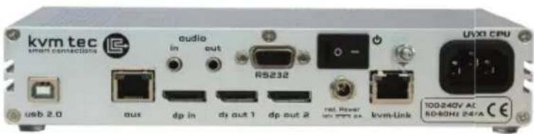
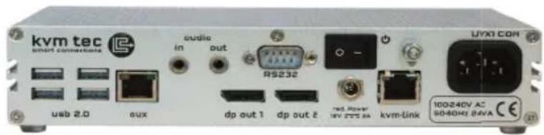
TABLE OF CONTENT
1. Introduction 5
1.1 Intended use 6
1.2 Safety intructions 7
1.3 Technical specifications 9
1.4 Product Elements 10
1.5 Meaning of the Led Indicators 12
2. Extender Installation 13
2.1 Unpacking and checking the content 13
2.2 Mounting kit 14
2.2.1 Mounting (optional) 14
2.3 Installing the Extender 15
2.4 Quickinstallation & Start up 16
2.5 Replacing the SFP module 18
2.6 Removing a CAT cable 19
2.7 Removing a fiber cable 19
3. Main menu & Settings 20
3.1 Using the on screen menu 21
3.2 System Status 21
TABLE OF CONTENT
3.3 Update Menu 22
3.4 Settings 26
3.4.1 Defining what DDC data your PC uses 27
3.4.2 Select Keyboard Layout 28
3.4.3 Keyboard Shortcuts 29
3.4.4 Mouse Settings 30
3.4.5 Managing Local Settings 31
3.5 About this device 32
4. Features 33
4.1. Menu Features 33
4.1.2 Multiview Commander 34
4.1.3 Switching in Multiview Commander 35
4.1.4 Mouse glide & switch 36
4.1.5 Point to Point 37
4.1.6 Matrix Switching System 37
4.1.7 USB Save Feature 37
4.1.8 Displayport Multistream 37
TABLE OF CONTENT
5. HUB Splitter 38
5.1. Built in HUB Splitter 38
6. Downscaling from 4K to HD 39
7. Maintenance and Care 40
7.1. Extender Care 40
7.2. Disposal 38
8.Support & First Aid 41
9.Cable Requirements 43
9.1. Requirements for CAT 7 Cable 43
9.2. Requirements for Fiber Cable 44
10. Requirements Network Switch 45
10.1. Recommended Swithces 46
11. Warranty 47
11.1. Extended Warranty 47
12. Address & Phone/Email 48
13. Notes
49
Congratulations on the purchase of your new Ultralineline UVX1/UVX1-F KVM Extender. You have bought a high quality extender. These instructions are part of this product. They contain important information regarding safety, use and disposal for every user of the Ultraline UVX1 and UVX1-F KVM Extender. Please familiarise yourself with the information within prior to using your product. Use the product only in the manner as described and for the areas of application as stated. Following proper use and maintenance, your Ultraline UVX1/UVX1-F KVM Extender will bring you joy for many years to come.
1. INTRODUCTION
1.1 INTENDED USE
This product is intended as a device for professional use, for transmitting USB and video signals over huge distances.
The product may only be used according to the instructions as described in this manual. All use, other than that described in this manual, is seen as unintended use. Modifications in the course of technological progress are reserved. In these user instructions the Ultraline UVX1/UVX1-F is referred to as 'product' or 'extender'. The UVX1/PC is referred to as the Local unit/CPU and the UVX1/Monitor is referred to as the Remote unit/ CON.
WARNING
The device may only be opened by an authorized technician.
Danger of electric shock!
1. INTRODUCTION
1.2 SAFETY INSTRUCTIONS
WARNING! Read and understand all safety instructions
- Follow all the instructions. This will avoid accidents, fire, explosions, electric shocks or other hazards that may result in damage to property and/or severe or fatal injuries. Please ensure that everyone who uses the product has read and followed these warnings and instructions.
- Keep all safety information and instructions for future reference and pass them on to subsequent users of the product.
The manufacturer is not liable for cases of material damage or personal injury caused by incorrect handling or non-compliance with the safety instructions. In such cases, the warranty will be voided
- This product is not intended for use by persons (including children) with restricted physical, sensory or intellectual capability or lack of experience and/or knowledge, unless they are supervised by a person who is responsible for their safety or provides them with instructions on how to use the product.
• Danger! Not for use in potentially explosive environments - Danger! Be vigilant at all times, and always take care around this product. Do not use electrical equipment if you are lacking in concentration or awareness, or are under the influence of drugs, alcohol or medication. Even a moment of inattentiveness can lead to serious accidents and injuries when using electrical equipment. Check the product and the cables for any damage before use. If there is any visible damage, a strong odour, or excessive overheating of components unplug all the connections immediately and stop using the product
- If the product is not installed and used in accordance with this manual, it may cause disruptive interference with radio or television reception or affect other electronic products in residential areas.
- Prior to connecting to the mains, make sure your local mains voltage matches the rating indicated on the product.
1. INTRODUCTION
• The product must be connected to a permanent and earthed AC wall socket•
- Protect the cables from tension, crushing and buckling and lay them so that people cannot trip over them.
• Use the device with a suitable, properly installed and easily accessible power outlet.
• Unplug the appliance during lightning storms or when not in use.
• Danger! Never touch the adapter with wet hands.
- Use the product within the specified performance limits.
- Do not place the product near heaters
- Do not drop or hit the product.
- Unplug all connections before cleaning the product. Do not use wipes or chemicals as these could damage the surface. Wipe the housing with a damp cloth. Electrical/electronic parts must not be cleaned
• Alterations to the product and technical modifications are not permitted
- Use the device with a suitable, properly installed and easily accessible power outlet. The appliance plug serves as a disconnection point.
1. INTRODUCTION
1.3 TECHNICAL SPECIFICATIONS
Type: KVM Extender (local unit-CPU und remote unit-CON)
Model: 4K Ultraline UVX1/UVX1-F KVM Extender
Power plug input voltage internal power supply
AC 100-240V/50-60Hz
IEC plug (IEC-320 C14)
supply tolerances AC and DC (e.g. AC: +/- 10%; DC: +20% / -15%)
Redundant
Power supply 12 VDC > 2A (optional)
Power requirement 15W withoutUSB devices
Operating
temperature 0 °C to 45 °C (32 bis 113 °F)
Storage semperature -25 °C bis 80 °C (-13 to 176 °F)
Relativ humidity: max. 80% (not condensing)
Casing material: anodized aluminum
Dimension: Local (CPU): 218 x 43 x 105 mm/8.58 x 1.69 x 4.14 inch,
676g/1.49ibs.
Weight Remote (CON): 218 x 43 x 105 mm /8.58 x 1.69 x 4.13 Inch,
707g /1.55lbs.
Shipment weight 2,30kg/5,07 lbs.
Expected product life 82 820 hours / 10 years
1. INTRODUCTION
1.4 ABOUT YOUR ULTRALINE EXTENDER
Local Extender (CPU)
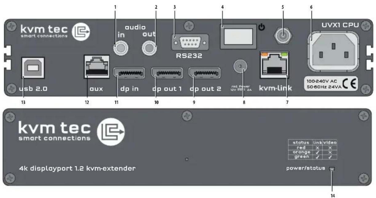
Nr. Name Function
1 audio in Audio in from PC
2 audio out Audio Out to PC
3 RS232 RS232
4 ON/OFF Power Switch ON/OFF
5 grounding Grounding screw
6 power Connection for 100-240V AC power supply
7 kvm-link Connection for CAT 7 cable or fi ber cable
8 dc Connection für 12V power supply
9 dpout 2 Displayport Output to Monitor 2
10 dpout 1 Displayport Output to Monitor 1
11 dpin DP Input from PC
12 AUX Auxiliary Gigabit Network Connector
13 USB 2.0 USB 2.0 to PC
14 power/status LED Displays the status of the extender14
1. INTRODUCTION
Remote Extender (CON)

Nr. Name Function
15 audio in Audio In from microphone etc.
16 audio out Audio Out to speakers etc.
17 RS232 RS232
18 power Power Switch ON/OFF
19 grounding Grounding screw
20 Power Connection for 100-240V AC power supply
21 kvm-link Connection for CAT 7 cable or fi ber cable
22 DC Connection für 12V power supply
23 dp out 2 Displayport Output to Monitor 2
24 dpout 1 Displayport Output to Monitor 1
25 AUX Auxiliary Gigabit Network Connector
26 USB USB 2.0 to keyboard /Muse
27 power/status LED Displays the status of the extender
1. INTRODUCTION
1.5 ABOUT THE STATUS LED
The power/status LED (14/27) can light red, orange or green. Table shows the meaning of each colour. Also see chapter 6 Troubleshooting.
| Colour Blinking Physical Link | Active Connection | Video Extended | USB Initialisation | UBS Data Received | Identify Command | Autoupdate Mode | |
| Main LED | |||||||
| Red - Yes No No Update Failed | |||||||
| Red Slow No No No | |||||||
| Orange - Yes Yes No | |||||||
| Orange Fast | Update in Progress | ||||||
| Green | - Yes Yes Yes | Update Succeeded | |||||
| Green | V. fast | Yes** | |||||
| Red/Green | V. fast | Yes | |||||
| RJ45 Socket LEDs * | |||||||
| Yellow | - No | ||||||
| Yellow | Slow Yes | ||||||
| Green | - | Yes | |||||
| Green | V. fast | Yes | |||||
* UVX only ** Rem. Only
Table : Meaning of LED indicators
2. EXTENDER INSTALLATION
2.1 UNPACKING AND CHECKING THE CONTENT
Before using the product for the first time it should be checked for damage. In case of damage due to transport inform the carrier immediately. Before delivery the product is checked for its function and its operating safety.
Make sure that the packaging contains the following content:
1x UVX1/local Extender CPU
1x UVX1/remote Extender CON
2x power cable IEC C13
1 x DP - DP cable 1,8 m/5,9ft
1x USB A-B cable 1,8m/5,9ft
8 x mounting feet
UVX Fiber 1 x SFP+ Module-Multimode up to 300m/984ft
2. EXTENDER INSTALLATION
2.2 MOUNTING KIT
2.2.1 MOUNTING (OPTIONAL)
Rack Mounting Kit RMK-F - Part No. 6230
The rack mounting kit RMK-F is for assembling kvm-tec Ultraline UVX1 extenders. It consists of 19" rack tray and an alu-faceplate.
2. EXTENDER INSTALLATION
2.3 INSTALLING THE EXTENDER
WARNING! Read and understand all safety information before installing the product.
The units can be set up to access point to point or over a Switching System with a host computer.
In the case of the latter, an additional 10 G Network Switch and a Windows PC od tablet with the Switching Manager must be installed With a Network Switch, each user can gain quick access to any of the required computers.

flowchart
graph LR
    PC["PC"] --> EXTENDER_LOCAL["EXTENDER LOCAL"]
    EXTENDER_LOCAL -->|Distance UP TO 100M / 160KM| EXTENDER_REMOTE["EXTENDER REMOTE"]
    EXTENDER_REMOTE -->|Usage| SCREEN["SCREEN"]
    SCREEN -->|Keyboard & Mouse| EXTENDER_REMOTE
point to point connection

flowchart
graph TD
    A["Switch"] --> B["PC"]
    A --> C["EXTENDER LOCAL"]
    A --> D["PC"]
    A --> E["EXTENDER LOCAL"]
    A --> F["PC"]
    A --> G["EXTENDER REMOTE"]
    A --> H["Screen, KEYBOARD & MOUSE"]
    A --> I["Screen, KEYBOARD & MOUSE"]
    A --> J["Screen, KEYBOARD & MOUSE"]
    A --> K["Screen, KEYBOARD & MOUSE"]
    A --> L["Screen, KEYBOARD & MOUSE"]
    A --> M["Screen, KEYBOARD & MOUSE"]
    A --> N["Screen, KEYBOARD & MOUSE"]
    A --> O["Screen, KEYBOARD & MOUSE"]
    A --> P["Screen, KEYBOARD & MOUSE"]
    A --> Q["Screen, KEYBOARD & MOUSE"]
    A --> R["Screen, KEYBOARD & MOUSE"]
    A --> S["Screen, KEYBOARD & MOUSE"]
    A --> T["Screen, KEYBOARD & MOUSE"]
    A --> U["Screen, KEYBOARD & MOUSE"]
    A --> V["Screen, KEYBOARD & MOUSE"]
    A --> W["Screen, KEYBOARD & MOUSE"]
    A --> X["Screen, KEYBOARD & MOUSE"]
    A --> Y["Screen, KEYBOARD & MOUSE"]
    A --> Z["Screen, KEYBOARD & MOUSE"]
    A --> AA["Screen, KEYBOARD & MOUSE"]
    A --> AB["Screen, KEYBOARD & MOUSE"]
    A --> AC["Screen, KEYBOARD & MOUSE"]
    A --> AD["Screen, KEYBOARD & MOUSE"]
    A --> AE["Screen, KEYBOARD & MOUSE"]
    A --> AF["Screen, KEYBOARD & MOUSE"]
    A --> AG["Screen, KEYBOARD & MOUSE"]
    A --> AH["Screen, KEYBOARD & MOUSE"]
    A --> AI["Screen, KEYBOARD & MOUSE"]
    A --> AJ["Screen, KEYBOARD & MOUSE"]
    A --> AK["Screen, KEYBOARD & MOUSE"]
    A --> AL["Screen, KEYBOARD & MOUSE"]
    A --> AM["Screen, KEYBOARD & MOUSE"]
    A --> AN["Screen, KEYBOARD & MOUSE"]
    A --> AO["Screen, KEYBOARD & MOUSE"]
    A --> AP["Screen, KEYBOARD & MOUSE"]
    A --> AQ["Screen, KEYBOARD & MOUSE"]
    A --> AR["Screen, KEYBOARD & MOUSE"]
    A --> AS["Screen, KEYBOARD & MOUSE"]
    A --> AT["Screen, KEYBOARD & MOUSE"]
    A --> AU["Screen, KEYBOARD & MOUSE"]
    A --> AV["Screen, KEYBOARD & MOUSE"]
    A --> AW["Screen, KEYBOARD & MOUSE"]
    A --> AX["Screen, KEYBOARD & MOUSE"]
    A --> AY["Screen, KEYBOARD & Mouse"]
    A --> AZ["Screen, KEYBOARD & Mouse"]
    A --> BA["Screen, KEYBOARD & Mouse"]
    A --> BB["Screen, KEYBOARD & Mouse"]
    A --> BC["Screen, KEYBOARD & Mouse"]
    A --> BD["Screen, KEYBOARD & Mouse"]
    A --> BE["Screen, KEYBOARD & Mouse"]
    A --> BF["Screen, KEYBOARD & Mouse"]
    A --> BG["Screen, KEYBOARD & Mouse"]
    A --> BH["Screen, KEYBOARD & Mouse"]
    A --> BI["Screen, KEYBOARD & Mouse"]
    A --> BJ["Screen, KEYBOARD & Mouse"]
    A --> BK["Screen, KEYBOARD & Mouse"]
    A --> BL["Screen, KEYBOARD & Mouse"]
    A --> BM["Screen, KEYBOARD & Mouse"]
    A --> BN["Screen, KEYBOARD & Mouse"]
    A --> BO["Screen, KEYBOARD & Mouse"]
    A --> BP["Screen, KEYBOARD & Mouse"]
    A --> BQ["Screen, KEYBOARD & Mouse"]
    A --> BR["Screen, KEYBOARD & Mouse"]
    A --> BS["Screen, KEYBOARD & Mouse"]
    A --> BT["Screen, KEYBOARD & Mouse"]
    A --> BU["Screen, KEYBOARD & Mouse"]
    A --> BV["Screen, KEYBOARD & Mouse"]
    A --> BW["Screen, KEYBOARD & Mouse"]
    A --> BX["Screen, KEYBOARD & Mouse"]
    A --> BY["Screen, KEYBOARD & Mouse"]
    A --> BZ["Screen, KEYBOARD & Mouse"]
    A --> CA["Screen, KEYBOARD & Mouse"]
    A --> CB["Screen, KEYBOARD & Mouse"]
    A --> CC["Screen, KEYBOARD & Mouse"]
    A --> CD["Screen, KEYBOARD & Mouse"]
    A --> CE["Screen, KEYBOARD & Mouse"]
    A --> CF["Screen, KEYBOARD & Mouse"]
    A --> CG["Screen, KEYBOARD & Mouse"]
    A --> CH["Screen, KEYBOARD & Mouse"]
    A --> CI["Screen, KEYBOARD & Mouse"]
    A --> CJ["Screen, KEYBOARD & Mouse"]
    A --> CK["Screen, KEYBOARD & Mouse"]
Set up Switching System up to 2000 endpoints
2. EXTENDER INSTALLATION
flowchart
graph TD
    A["PC"] -->|2. USB to PC| B["kvm tec"]
    B --> C["output"]
    C --> D["RS232"]
    D --> E["UVX1 CPU"]
    E --> F["USB 2.0"]
    F --> G["aux"]
    G --> H["dp in"]
    H --> I["dp out 1"]
    I --> J["dp out 2"]
    J --> K["kvm Unk"]
    K --> L["100-240V AC"]
    L --> M["24VA"]
    M --> N["3. Networkable CAT 6a/7 up to 100m/328ft"]
    N --> O["4. DP out to Monitor"]
    O --> P["SCREEN"]
    P --> Q["SCREEN"]
    Q --> R["screen"]
    R --> S["4. DP out to Monitor"]
    S --> T["4. Audio from microphone"]
    T --> U["5. Audio to speaker"]
    U --> V["6. Audio from microphone and mouse"]
    V --> W["2. USB from keyboard and mouse"]
    W --> X["SCREEN"]
    X --> Y["4. DP to Monitor"]
    Y --> Z["4. Power plug 100-240 VAC"]
    Z --> AA["1. power plug 12V > 2A"]
2. EXTENDER INSTALLATION
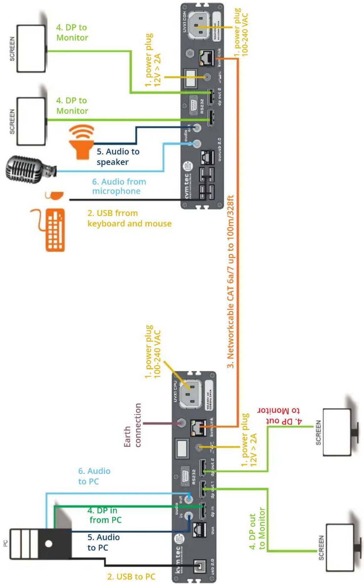
Quick Installation ULTRALINE 4K
local / CPU - remote/ CON
- Connect the CON / Remote and the CPU / Local Unit with the supplied IEC power cable. Optionally, you can also use a 12V > 2A power supply.
- Now connect the USB cable to a USB port on your PC and connect the other end to the CPU / Local Unit. Connect keyboard and mouse to the CON / Remote Unit.
- Connect the CPU / Local and the CON / Remote Unit with a network cable.
- Connect the DP cable in the DP socket of the PC -in and to the DP socket DP / in of the local device and connect the screen on the remote side with the DP cable. Optionally, connect the DP cable from the Local DP / out to another monitor.
- Then connect PC audio out with the audio cable to Local Audio in. Connect audio / out via the audio cable
- Almost done! Now connect the audio cable Local Audio / out to the PC Audio in and Remote Audio / in with the audio cable to the microphone.
HAVE FUN - your kvm-tec Extender is now in use for many years (MTBF approx 10 years)
Displayport-cable
Please note that the recommended length of the display port cable should be max. 1.8m,5.9 ft otherwise interference-free 4K transmission may not be guaranteed.
When the UVX is connected to a TV with an HDMI adapter
Some Tvx require the HDMI UHD Clour mode to be switched on, otherwise picture interference will occur
Menu navigation : Example Samsung UE55NU7170/72
Home - Settings-General-External Device Management - Enable HDMI UHD Colour on HDMI
2. EXTENDER INSTALLATION
2.4 START UP
To start up the system:
- Make sure that the two monitors and the computer are switched on.
- If you are using a Network Switch, connect the power cable to an earthed wall socket.
- Connect both extender power cables (6 / 20) to an earthed wall socket. Switch on both units. Both extenders start an initialization process. The status LED blinks some seconds red and changes to green after a successful connection. The monitor will displays your computer's desktop or any open applications.
2.5 REPLACING THE SFP MODULE
The UVX1-F is delivered with a multimode SFP module.
To replace an SFP module with a different SFP+ module:
- Remove the black dust protector from the SFP+ module.
- Pull the metal latch of the SFP+ module forwards until it is at a right angle.
- Replace the SFP+ module with the other module. Put the metal latch back in position. Only use SFP+ modules from kvm-tec, or recommended by kvm-tec.

2. EXTENDER INSTALLATION
2.6 REMOVING A CAT CABLE
To remove a CAT7 cable:
- Press the latch down and slowly pull the cable out.

2.7 REMOVING A FIBER CABLE
To remove a fi ber cable:
- Press the latch down and slowly pull the cable out.

3. MAIN MENU & SETTINGS
3. USING THE ON SCREEN MENU
Use the monitor and keyboard to access the main menu.Z
Access to the main menu
- Make sure that the extenders, monitors and computer are turned on
- Press the Scroll Lock button fi ve times hintereinander. The main menu and the overview of the submenus are displayed.
- To access a submenu, press the corresponding key or navigate with the arrow keys up and down to the corresponding line and then press Enter key.

SCREEN „OSD menu“
Main menu short cuts :
Press
S System status menu system status/ current status
F Features Menu activated features
U Update update firmware
G Settings settings
A About this device Informationen about the unit
3. MAIN MENU & SETTINGS
3.1. SYSTEM STATUS
By pressing the „S“ key or by selecting the arrow keys, you access the status menu, where you will find information about hardware and software versions, as well as the activated upgrades The menu displays information about the connection, the resolution of the video channel and the USB status. The current Firmware version is displayed in the upper left corner.
The link status indicates whether a connection is possible.
Video and USB display data transfer status
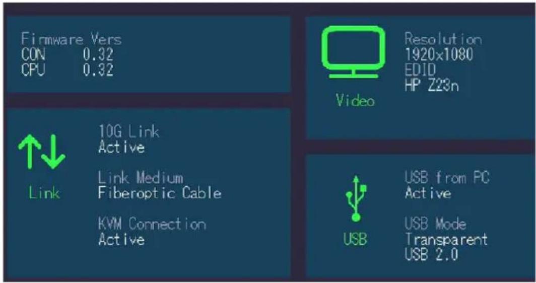
SCREEN „System Status“
3.2. FEATURES MENU
Pressing the „F“ key or selecting the arrow keys will take you to the features menu, where you can operate the activated features.
go to chapter 5 FEATURES
3. MAIN MENU & SETTINGS
3.3 UPDATE MENU
Display of firmware version
By pressing the „U“ key or by selecting the arrow keys, you reach the update menu, in which the firmware of the Extender will be displayed and can be updated.

SCREEN „Update „
3. MAIN MENU & SETTINGS
- The current version of the firmware can be downloaded at http://www.kvm-tec.com/support. Each update file contains a detailed description of the update process. For further information please refer to the update chapter
- Connect the USB stick to the CON (REMOTE) unit (wait a few seconds until the USB stick is connected to the CON unit).
- Open the update menu with the „U“ key.
- Press „S“ to display this file
- The firmware is displayed with „Configuration found“
- Press „U“ to start the update on the Remote (CON) Unit

SCREEN „Update“
3. MAIN MENU & SETTINGS

SCREEN „ Update"
The UPDATE process is now started and takes place in two steps:
- Erasing flash: erases the memory
- Updating: the new version is installed
3. MAIN MENU & SETTINGS
The upgrade menu shows all already installed and activated settings:
Analog sound Fix displayed (active)
Embedded Sound Fix displayed (acktive)
RS232 Fix displayed (active)
USB Save Feature
(no mass storage) on/off default off
Matrix Switching
USB MEMORY UPGRADES
USB flash memory and external storage devices can be accessed via the extender via the already activated upgrade USB memory.
The USB memory upgrade can be switched off and on by pressing „M“.
SOUND
The upgrade is already activated and transmits sound in CD quality analog over 3.5mm sockets in both directions.
Furthermore, the embedded sound information of the display port is transmitted.
RS 232
A maximum serial transfer rate of 115200kBd possible
It is not necessary to set the baud rate and bits per character.
„R“ appears in the menu item and this function is permanently active.
Switching up to 2000 endpoints
The already activated Switching upgrade can be activated from the Switching menu (in the main menu).
By pressing „S“, you can access the switching menu and thus activate or de-activate the switching upgrade.
In the main menu you can configure the switching system with „S“.
3. MAIN MENU & SETTINGS
3.4 SETTINGS
By pressing the „G“ key or selecting the arrow keys you will have access to the Settings menu, where you can access all Extender settings.

SCREEN „Settings“
3. MAIN MENU & SETTINGS
3.4.1 DEFINING WHAT DDC DATA YOUR PC USES
In the DDC Information menu, the user can define which DDC information is used by the PC.
Definition of the DDC information used in the PC:
- Make sure that the main menu is open (5 x scroll)
- Press the O to display the DDC-option menu
- Press 1 to display the DDC information of the monitor connected to the remote (CON)
- The Extender is connected. The DDC information is automatically saved
- Press 2 for a fix resolution 1920 x 1080
- Press 3 for a fix resolution 2560 x 1440
- Press 4 for a fix resolution 3840 x 2160
Press ESC to return to the main menu
Current Setting: FIX 1920 × 1080
1 Remote Monitor
2 FIX 1920 × 1080
3 FIX 2560 × 1440
4 FIX 3840 × 2160
SCREEN „DDC/EDID Settings“
3. MAIN MENU & SETTINGS
3.4.2 SELECT KEYBOARD LAYOUT
In the Keyboard Layout menu you can switch between the keyboard layouts with which you can navigate the on screen display menu (OSD).
Press the K button. The Keyboard Local menu opens:
Press E to select English (QWERTY).
Press D to select English (QWERTY).
Press F to select French (AZERTY).
3. MAIN MENU & SETTINGS
3.4.3 KEYBOARD SHORTCUTS
By pressing the „S“ key or by selecting the arrow keys you will access the Keyboard Shortcuts menu.
If you want to change one of the shortcuts, you have to press the letter specified for the shortcut.
Now you can press any key or key combination.
(Please note that only a key combination with the keys 1 or F1 is possible with point F.)
Use the arrow keys to determine the number of keystrokes required to trigger the shortcut.
Then confirm with Enter.
M Main Menu 5x < SCROLLLOCK >
L Device List < LEFT_CTRL + LEFT_ALT + F12 >
S Status < LEFT_CTRL + LEFT_ALT + F9 >
D Disconnect < LEFT_CTRL + LEFT_ALT + F11 >
F Favourites Prefix < LEFT_CTRL + LEFT_ALT + F1 >
Enter to Edit
SCREEN „Keyboard shortcuts“
3. MAIN MENU & SETTINGS
3.4.4 MOUSE SETTINGS
By pressing the „G“ buttonor by selecting the arrow buttons, you enter the Mouse Settings menu.
With the M button you will open the Mouse Settings where you can adjust the speed of the mouse with the arrow keys.

SCREEN „Mouse Settings“
3. MAIN MENU & SETTINGS
By pressing the „G“ key, or by selecting the arrow keys, you can access the Menu Local Settings
Press the „L“ key to open the Local Settings.
Here you will find the Remote Wakeup setting.

SCREEN „Local Settings“
4. EXTENDER FEATURES
3.5 ABOUT THIS DEVICE
By pressing the „A“ key or by selecting the arrow keys, you access the info menu, where you will find information about hardware and software versions, as well as activated upgrades.
General:
Hardware Version: 1.1
Firmware Version: 0.32
Upgrades:
Analogue Sound: enabled
Embedded Sound: enabled
RS232: enabled
SCREEN „About this device“
4. EXTENDER FEATURES
4. FEATURES
4.1 MENU FEATURES
Pressing the „F“ key or selecting the arrow keys, you will access the FEATURES menu, where you can select all the functions and the features.
V- Multiview Commander
M- Mouse Glide & Switch
P- Point to point Mode on/off
S- Matrix Switching Mode
D- Displayport Multistream
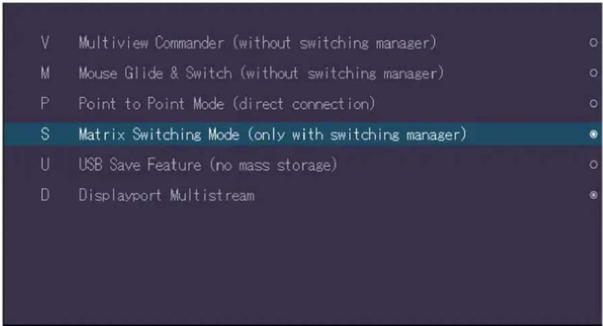
SCREEN Menü FEATURES
Two features are already pre-installed, which can be set by pressing „F“ in the main menu. You can activate either the 4K Multiview Commander or the Mouse Glide& Switch.
4. EXTENDER FEATURES
4.1.2 MULTIVIEW COMMANDER
By pressing „V“ you activate the 4K Multiview Commander and therefore you can display and operate 4 PC screens on a 4K Moniotr simultaneously.
The 4K Multitview Commander requires up to 4 MX local (CPU) devices on the CPU side, which are connected to the UVX CON part via a network switch.
If Local Units are not displayed, they can be found by pressing the F key. Use the A key to activate/deactivate the Auto Connection function.
To change the Highlight Settings press the H key.
This key is used for the visual position display of the mouse in your setup.
By using the arrow keys you can select from the four monitors displayed to assign the desired position of the Local Units.
Use the Number buttons to select a Local Unit and press the C button to confirm. If you want to disconnect a local unit, use the D key.
To disconnect all connections press the E key.

SCREEN „Multiview Commander“
4. EXTENDER FEATURES
4.1.3 SWITCHING IN MULTIVIEWCOMMANDER
With a multiview commander setup - multiple sources can be displayed on one or more monitors.
The displayed source can be selected as follows:
Move the mouse to the area where the source is to be displayed.
Then open the „Switching List“ with OSD, either by pressing the scroll key 5 times and then into the menu item „L“ or by shortcut (default is Ctrl+ALT+F12).

SCREEN „ Switching List“
Then confirm the desired source with the Enter key. The selected source appears in the quadrant in which the mouse is located.
By pressing the „D“ key, the displayed source can be separated again. The menu can be closed with the ESC key.
4. EXTENDER FEATURES
4.1.4 MOUSE GLIDE & SWITCH
Multiple UVX Extenders can be configured to automatically switch the USB operation of any computer and follow the mouse movement.
Up to 8 monitors can be configured both vertically and horizontally.
Press „M“ to go to the configuration of the Mouse Glide & Switch function. The corresponding local parts are connected to the REM part via a 10 G network switch.
To change the existing layout press the T button.
If not all extenders are available, these can be found with the F key. Use the arrow keys to navigate to the screen symbols and assign a local unit with the L key and a number and a remote unit with the R key and a number. This must be confirmed with Enter.
With the key „I“ you can identify assigned extenders by starting the LED to blink when activated.
With „B“ you reach the border settings, in which you can set the visual position display of the mouse in your setup.
Use the C key to reset all settings.
Press the A key to apply all the settings you have made.

SCREEN „Mouse glide& switch“
4. EXTENDER FEATURES
4.1.5 POINT TO POINT
By pressing „P“ you reach the configuration point to point. By default, the remote is directly connected to the Local.
4.1.6 MATRIX SWITCHING SYSTEM
Pressing „S“ takes you to the Matrix Switching System configuration.
If this function is active, the Multiview Commander and Mouse Glide functions are controlled via the Switching Manager software (see Switching Manager manual).
All functions of the Switching System can be managed via the Switching Manager Software.
With this link you can download the Switching Manager Software Manual : www.kvm-tec.com/dt/support/handbuecher
4.1.7 USB SAVE FEATURE
Press „U“ to go to the USB SAVE FEATURE configuration.
With the activation, the intrusion of computer viruses can be prevented via USB-mass storage. Data from a connected USB mass storage device cannot be accessed.
4.1.8 DISPLAYPORT MULTISTREAM
By pressing „D“ you access the Displayport Multistream configuration and activate the Mustistream functionality
5.HUB SPLITTER
5. HUB SPLITTER
5.1 BUILT - IN MST HUB SPLITTER
The built-in MST/HUB splitter allows the transmission of two different image contents via one cable up to a max. resolution of 2 - times 2560 x 1440 @ 60 Hz or 2 - times 3840 x 2160 @ 30 Hz
The CPU (local) and the CON (remote) part has two video outputs with splitter / multistream function.
With a 4k resolution one screen content is transmitted which is available on both outputs at the same time. With a
With a resolution of 2 - times 2560 x 1440 @ 60 Hz or 2 - times 3840 x 2160 @ 30 Hz two different picture contents can be transferred to two monitors.
Both the graphics card and the monitor must comply with the Displayport Standard 1.2. For some monitors the Display port function 1.2 must be activated in the monitor menu.

flowchart
graph TD
    A["PC 1"] -->|4K DP 1.2| B["4K EXTENDER LOCAL (DP-IN)"]
    B --> C["OR"]
    C --> D["4K EXTENDER REMOTE (DP OUT)"]
    D --> E["4K MONITOR 1"]
    D --> F["4K MONITOR 1"]
    D --> G["4K MONITOR (36kV/960)"]
    D --> H["4K MONITOR (36kV/960)"]
    D --> I["4K EXTENDER REMOTE (DP OUT)"]
    I --> J["4K EXTENDER REMOTE (DP OUT)"]
6. DOWNSCALING
6. DOWNSCALING FROM 4K TO HD
Extenders can automatically downscale 4K (3840 x 2160) resolutions to Full HD (1920 x 1080) when a Full HD (1920 x 1080) monitor is used.
7. MAINTANCE & CARE
7.MAINTANCE AND CARE
7.1 EXTENDER CARE
Caution! Do not use solvent-containing cleansers. Do not use wipes, alcohols (e.g. spiritus) or chemicals as these could damage the surface.
7.2. DISPOSAL

natural_image
Symbol of a trash bin with crossed lines indicating no waste or discharge, and a solid black rectangle below (no text or labels)This symbol on the product, the accessories or packaging indicates that this product must not be treated as unsorted municipal waste, but must be collected separately! Dispose of the product via a collection point for the recycling of waste electrical and electronic equipment within the EU and in other European countries that operate separate collection systems for waste electrical and electronic equipment. By disposing of the product in the proper manner, you help to avoid possible hazards for the
environment and public health that could otherwise be caused by improper treatment of waste equipment. The recycling of materials contributes to the conservation of natural resources.
Therefore do not dispose of your old electrical and electronic equipment with the unsorted municipal waste.
The packaging is made of environmentally friendly materials, which may be disposed through your local recycling facilities. By disposing of the packaging and packaging waste in the proper manner, you help to avoid possible hazards for the environment and public health.
8. SUPPORT & FIRST AID
kvm-tec
First Aid
smart connection


flowchart
graph TD
    A["No Power (No LED)"] --> B["Check the powerplug"]
    B --> C["Is the power supply ok? Try another Unit"]
    C --> D["Try reprogramming the Unit by using a JTAG programmer"]
    D --> E["Contact kvm-tec support"]

    F["USB is not working"] --> G["Are the USB Devices plugged in correctly?"]
    G --> H["Is the USB cable on the Local side plugged into the PC?"]
    H --> I["Are the USB Devices working directly on the PC?"]
    I --> J["Replace the USB cable from PC to the Local Extender"]
    J --> K["Check if local and remote Unit have the same firmware"]
    K --> L["Check if the local or the remote Unit is causing the problem by swapping first the local and then the remote Unit to another Unit"]
    L --> M["Contact kvm-tec support"]

    N["No Video"] --> O["Check if all cables are plugged in correctly"]
    O --> P["Check if the PC is sending a Image by plugging in a monitor on the local out of the local Unit"]
    P --> Q["Check if the DDC is set correctly (in menu under point „O“)"]
    Q --> R["Check if both Units have the correct firmware"]
    R --> S["Contact kvm-tec support"]

    T["Video error (stripes in the picture)"] --> U["Check if all cables are plugged in correctly"]
    U --> V["Check if the PC is sending a Image by plugging in a monitor on the local out of the local Unit"]
    V --> W["Check if the DDC is set correctly (in the menu under point „o“)"]
    W --> X["Check if local and remote Unit have the correct firmware"]
    X --> Y["Check if the network switch is setup correctly and has enough bandwidth"]
    Y --> Z["Check if other units have the same behaviour"]
    Z --> AA["Contact kvm-tec support"]
We are here for you to answer your questions about installation?
Manual download www.kvm-tec.com
or
kvm-tec Installationchannel on our homepage
personally +43 2253 81912

8. SUPPORT & FIRST AID
| Error Cause solution | ||
| LED is not lighting | The devices get no power | Is the power supply connected?Ne start device |
| LED is lighting in red | No connection between Loc and Rem | Check if the RJ45/network cable is connected well.(Clicking noise when plugging in)Control both, if it does not work please send an e-mail to support@kvm-tec.com or phone +42 2253 81912 |
| LED is lighting in orange | No picture on the monitor | Check if the local (PC) cable is connected well.Check if the remote (monitor) cable is connected well.If everything is connected well but no function appears,reconnect power supply again.If the menu is visible, press the O key and choose the resolution of the monitor. Then press the assigned number on your keyboard. |
| LED is lighting in green | Screen occurs but the keyboard is not working | Plug out/in USB of keyboard and wait until driver is installed (after few seconds).Check all USB connections on both sides (Local and Remote)If it is still not working, plug out/in USB once more |
| LED is lighting in green | no audio | Establish audio connection:plug stereo-jack to the audio output of the PC (green)connection with local: INremote: headset OUTEstablish microphone connection:plug stereo-jack to the microphone input of the PC (pink)connection with local OUT.connect the mikrophone on the CON side. |
| Error Cause solution | ||
| LED is lighting in green | The screen flkers,has an incorrect display | Install current fi rmware from our homepage http://www.kvm-tec.com/support |
| LED is lighting in green | Different firmwareor USB is not compatible | Please contact the kvm-tec support team via e-mail:support@kvm-tec.com or by phone: +43 2253 81912 30 |
| LEDS different different firmware | To enter on screen menu/check firmware version:To enter the On screen menu, press the Scroll Lock keyfi ve times in quick succession. The currently installedfi rmware version is displayed below the menuIf fi rmware update does not work, please send an e-mailto support@kvm-tec.com | |
9. CABLE REQUIREMENTS
9. CABLE REQUIREMENTS
9.1 REQUIREMENTS FOR CAT 7 CABLE
A Cat 7 cable should meet the following requirements:
- The pins are connected 1:1. Caution: the cable pairs must be twisted to EIA/TIA-568A (rare) or EIA/TIA-568 B (common) pairs.
- Erroneous assignments cannot be found with a simple cable tester.
- The pins for the green pair of wires are not adjacent to one other.
- The cable must at the very least meet the CAT 7 specifications and be suitable for 10 Gigabit transmission.
- The cable should meet one of the following standards: Class D ISO/IEC 11801:2002 or EN 50173-1:2002. Schema EIA/TIA-568 B.
- Only use shielded installation cable with min. cross section of 24 AWG throughout the length.
- The shield should be contiguous and connected to both ends. A shielded patch cable is allowed for connection to the device. Schema EIA/TIA-568 B
| Pin Color |
| 1 Orange/White |
| 2 Orange |
| 3 Green/White |
| 4 Blue |
| 5 Blue/White |
| 6 Green |
| 7 Brown/White |
| 8 Brown |
9. CABLE REQUIREMENTS
9.2 REQUIREMENTS FIBER CABLE
9.2.1 MULTI-MODE (STANDARD)
A multi-mode fiber cable should meet the following requirements
- The maximum length should be 300 m (984ft). The UVX-F is equipped with a multimode - SFP+ module, which allows a transmission distance of up to 300 m /984ft
• Dedicated fiber optic connection cable type OM4 Duplex Multimode with LC plug
10. SWITCH SPECIFICATION
10 REQUIREMENTS NETWORK SWITCH
The entire switching network system requires its own dedicated network. For security reasons it cannot be integrated into an existing company network.
The network switch must meet the following specifications:
10 Gigabit Switch, with a port-to-port transfer rate of 10 Gigabit/second
The following switches have all been tested and verified and will work with all kvm-tec Ultraline extenders.
10. SWITCH SPECIFICATION
10.1 RECOMMENDED SWITCHES
SWITCH

natural_image
Orange rectangular object with white horizontal bars and four small square cutouts (no text or symbols)Multiple Switch
Single Switch
| Art Nr | Item Nr Product | |
| CATx SWITCHHE | ||
| 6141 | NS24RJ/2SFP/2SFP+ Network | Switch 24x RJ45 1000 Base-T / 2x SFP 1G / 2x SFP+ 10G in Kombination mit MX |
| 6171 | NS48RJ+/2SFP+ Network Switch | 48x RJ45 10G / 2x SFP+ 10G |
| FIBER SWITCHHE | ||
| 6161 | NS48SFP+/4QSFP+ Network | Switch 48x SFP+ 10G / 4x QSFP+ |
11. WARRANTY
11. WARRANTY
The warranty period is 24 months from the date of purchase. The warranty expires in case of:
- External effort
- improper maintenance
• Violation of the operating instructions
• lightning damage
Please, contact us first before returning the product.
11.1 EXTENDED WARRANTY

2 years standard warranty

Art Nr 9003 warranty extension to 5 years per Set
Art Nr 9002 warranty extension to 5 years per Unit
12. ADDRESS & PHONE / EMAILS
12. ADDRESS & PHONE/EMAIL
If you have any questions about our products, please contact kvm-tec or your dealer.
kvm-tec electronic gmbh
Email: support@kvm-tec.com
Web: www.kvm-tec.com
Find our newest updates and FAQs on our homepage: http://www.kvm-tec.com/support
kvm-tec Inc. USA Sales p+1 213 631 3663 & +43 225381912-22
email: officeusa@kvm-tec.com
kvm-tec ASIA-PACIFIC Sales p +9173573 20204
email: sales.apac@kvm-tec.com
kvm-tec China Sales - P + 86 1360 122 8145
email: chinasales@kvm-tec.com
13. NOTES

- TABLE OF CONTENT
- Introduction 5
- Extender Installation 13
- Main menu & Settings 20
- Features 33
- HUB Splitter 38
- Downscaling from 4K to HD 39
- Maintenance and Care 40
- 8.Support & First Aid 41
- 9.Cable Requirements 43
- Requirements Network Switch 45
- Warranty 47
- Address & Phone/Email 48
- Notes
- INTRODUCTION
- INTENDED USE
- WARNING
- SAFETY INSTRUCTIONS
- WARNING! Read and understand all safety instructions
- TECHNICAL SPECIFICATIONS
- ABOUT YOUR ULTRALINE EXTENDER
- Nr. Name Function
- ABOUT THE STATUS LED
- EXTENDER INSTALLATION
- UNPACKING AND CHECKING THE CONTENT
- MOUNTING KIT
- MOUNTING (OPTIONAL)
- INSTALLING THE EXTENDER
- Quick Installation ULTRALINE 4K
- HAVE FUN - your kvm-tec Extender is now in use for many years (MTBF approx 10 years)
- Displayport-cable
- When the UVX is connected to a TV with an HDMI adapter
- START UP
- REPLACING THE SFP MODULE
- To replace an SFP module with a different SFP+ module:
- REMOVING A CAT CABLE
- To remove a CAT7 cable:
- REMOVING A FIBER CABLE
- To remove a fi ber cable:
- MAIN MENU & SETTINGS
- USING THE ON SCREEN MENU
- Access to the main menu
- Press
- SYSTEM STATUS
- FEATURES MENU
- UPDATE MENU
- Display of firmware version
- USB MEMORY UPGRADES
- SOUND
- RS 232
- Switching up to 2000 endpoints
- SETTINGS
- DEFINING WHAT DDC DATA YOUR PC USES
- Definition of the DDC information used in the PC:
- SELECT KEYBOARD LAYOUT
- KEYBOARD SHORTCUTS
- MOUSE SETTINGS
- EXTENDER FEATURES
- ABOUT THIS DEVICE
- FEATURES
- MENU FEATURES
- MULTIVIEW COMMANDER
- SWITCHING IN MULTIVIEWCOMMANDER
- MOUSE GLIDE & SWITCH
- POINT TO POINT
- MATRIX SWITCHING SYSTEM
- USB SAVE FEATURE
- DISPLAYPORT MULTISTREAM
- 5.HUB SPLITTER
- HUB SPLITTER
- BUILT - IN MST HUB SPLITTER
- DOWNSCALING
- DOWNSCALING FROM 4K TO HD
- MAINTANCE & CARE
- 7.MAINTANCE AND CARE
- EXTENDER CARE
- DISPOSAL
- SUPPORT & FIRST AID
- kvm-tec
- First Aid
- smart connection
- CABLE REQUIREMENTS
- REQUIREMENTS FOR CAT 7 CABLE
- REQUIREMENTS FIBER CABLE
- MULTI-MODE (STANDARD)
- SWITCH SPECIFICATION
- REQUIREMENTS NETWORK SWITCH
- RECOMMENDED SWITCHES
- WARRANTY
- EXTENDED WARRANTY
- ADDRESS & PHONE / EMAILS
- ADDRESS & PHONE/EMAIL
Brand : KVM-TEC
Model : Ultraline UVX1-FL
Category : AV Extension