
HPC-8224 - Server Advantech - Free user manual and instructions
Find the device manual for free HPC-8224 Advantech in PDF.


| Type | 4U Rackmount Server Chassis |
| Form Factor | 4U (19-inch rack compatible) |
| Dimensions (W x H x D) | 430 mm x 176 mm x 692 mm |
| Weight | Approximately 18 kg (empty) |
| Supported Motherboard | CEB or EEB form factor (dual Intel Xeon) |
| Drive Bays | 24 x 3.5" Hot-Swap SAS/SATA bays |
| Expansion Slots | 7 low profile or full-height PCIe slots |
| Power Supply | 2U redundant 1200W Platinum (2 modules) |
| Cooling | 3 x 120mm hot-swap fans (middle), 2 x 80mm rear fans |
| Front I/O | 2 x USB 3.0, power button, reset, status LEDs |
| Operating Temperature | 0°C to 35°C (32°F to 95°F) |
| Storage Temperature | -20°C to 60°C (-4°F to 140°F) |
| Relative Humidity | 10% to 85% non-condensing |
| Safety Standards | CE, FCC Class A, UL |
| Maintenance | Use a soft dry cloth for cleaning; avoid liquids. Ensure power is disconnected before servicing. |
| Cleaning | Regularly dust the front intakes and fan filters to prevent overheating. |
| Spare Parts | Contact Advantech or authorized distributors for replacement fans, power supplies, drive trays. |
| Repairability | Hot-swap components (drives, fans, PSUs) can be replaced without tools. |
| General Information | Designed for data centers and enterprise storage; supports advanced RAID controllers and redundant operation. |
Frequently Asked Questions - HPC-8224 Advantech
User questions about HPC-8224 Advantech
0 question about this device. Answer the ones you know or ask your own.
Ask a new question about this device
Download the instructions for your Server in PDF format for free! Find your manual HPC-8224 - Advantech and take your electronic device back in hand. On this page are published all the documents necessary for the use of your device. HPC-8224 by Advantech.
USER MANUAL HPC-8224 Advantech
natural_image
Illustration of four electronic circuit boards with white outlines on a purple background, no text or symbols present.HPC-8224
2U Storage Chassis for EATX/ATX/MicroATX Serverboard with 24 Hot-Pluggable Drive Bays
2U 储存服务器适用 EATX/ATX/MicroATX 服务器主板,支持 24 个热抽拔硬盘
2U 储存伺服器適用 EATX/ATX/MicroATX 伺服器主機板,支援 24 個熱抽拔硬碟
The documentation and the software included with this product are copyrighted 2016 by Advantech Co., Ltd. All rights are reserved. Advantech Co., Ltd. reserves the right to improve the products described in this manual at any time without notice. No part of this manual may be reproduced, copied, translated, or transmitted in any form or by any means without the prior written permission of Advantech Co., Ltd. The information provided in this manual is intended to be accurate and reliable. However, Advantech Co., Ltd. assumes no responsibility for its use, nor for any infringements of the rights of third parties that may result from its use.
HPC-8224 is the trademark of Advantech Co., Ltd.
All other product names or trademarks are the properties of their respective owners.
HPC-8224 是研华公司的商标。
For technical support and service, please visit our support website at http://support.advantech.com
- Read these safety instructions carefully.
- Retain this user manual for future reference.
- Disconnect the equipment from all AC outlets before cleaning. Use only a damp cloth for cleaning. Do not use liquid or spray detergents.
- For pluggable equipment, the power outlet must be located near the equipment and easily accessible.
- Protect the equipment from humidity.
- Place the equipment on a reliable surface during installation. Dropping or letting the equipment fall may cause damage.
- For rack-mounted equipment, install the pallets or sliding rails into the device rack.
- Do not leave this equipment in an unconditioned environment where the storage temperature fluctuates below 0 ^ ( 32 ^ ) or above 35 ^ ( 95 ^ ). This may damage the equipment.
- The openings on the enclosure are for air convection. Protect the equipment from overheating. Do not cover the openings.
- Ensure the power voltage is correct before connecting the equipment to a power outlet.
- Position the power cord away from high-traffic areas. Do not place anything over the power cord.
- All cautions and warnings on the equipment should be heeded.
- If unused for a long time, disconnect the equipment from the power source to avoid damage from transient overvoltage.
- Never pour liquid into an opening. This can cause fire or electrical shock.
- Never open the equipment. For safety reasons, the equipment should be opened only by qualified service personnel.
- If one of the following situations occurs, have the equipment checked by service personnel:
■ The power cord or plug is damaged.
- Liquid has penetrated into the equipment.
■ The equipment has been exposed to moisture.
The equipment is malfunctioning, or does not work according to the user manual.
■ The equipment has been dropped and damaged.
■ The equipment shows obvious signs of breakage.
- The equipment features a battery-powered real-time clock circuit. Batteries are at risk of exploding if incorrectly replaced. Replace only with the same or equiv-
alent type recommended by the manufacturer. Discard used batteries according to the manufacturer's instructions.
- The computer is equipped with CD drives that comply with appropriate safety standards including IEC 60825.
CLASS 1 LASER PRODUCT KLASSE 1 LASER PRODUKT
- This device complies with Part 15 of the FCC rules. Operation is subject to the following two conditions:
(1) The device may not cause harmful interference.
(2) The device must accept any interference received, including interference that may cause undesired operation.
CLASS I LASER PRODUCT KLASS I LASER PRODUKT
CLASS I LASER PRODUCT KLASS I LASER PRODUKT
A Message to the Customer/ 致客戶的訊息
Each Advantech product is built to the most exact specifications to ensure reliable performance in the harsh and demanding conditions typical of industrial environments. Whether your new Advantech equipment is destined for a laboratory or factory floor, you can be assured that the product will provide the reliability and ease of operation for which Advantech is renowned. Your satisfaction is our primary concern. Below is a guide to Advantech's customer services. To ensure you receive the full benefit of our services, follow the instructions carefully.
We want you to get the best performance possible from your products. Should you encounter technical difficulties, we are available to provide assistance. Answers to the most frequently asked questions can be found in the product documentation. These answers are generally a lot more detailed than the advice provided over the phone.
Please consult this manual first. If you still cannot find the answer, gather all the information or questions that apply to your problem, and with the product to hand, call your dealer. Our dealers are well trained and ready to provide the support you need to get the most from your Advantech products. Most problems reported are minor and can be easily solved over the phone.
In addition, free technical support is available from Advantech engineers every business day. We are always ready to provide advice about application requirements or specific information regarding the installation or operation of any of our products.
Advantech warrants the original purchaser that all of its products will be free from defects in materials and workmanship for two years from the date of purchase.
This warranty does not apply to any products that have been repaired or altered by persons other than repair personnel authorized by Advantech, or products that have been subject to misuse, abuse, accident, or improper installation. Advantech assumes no liability under the terms of this warranty as a consequence of such events.
Because of Advantech's high quality-control standards and rigorous testing, most customers never need to use our repair service. If an Advantech product is defective, it will be repaired or replaced at no charge during the warranty period. For out-of-warranty repairs, customers are billed according to the cost of replacement materials, service time, and freight. Please consult your dealer for more details.
If you think you have a defective product, follow these steps:
- Collect all the information about the problem encountered. (For example, CPU speed, Advantech products used, other hardware and software used, etc.) Note anything abnormal and list any onscreen messages displayed when the problem occurs.
- Call your dealer and describe the problem. Please have your manual, product, and any helpful information readily available.
- If your product is diagnosed as defective, obtain a return merchandise authorization (RMA) number from your dealer. This allows us to process your return more quickly.
- Carefully pack the defective product, a completed Repair and Replacement Order Card and a proof of purchase date (such as a photocopy of your sales receipt) into a shippable container. Products returned without a proof of purchase date are not eligible for warranty service.
- Write the RMA number clearly on the outside of the packaging and ship the package prepaid to your dealer.
When opening the product, ensure that the following materials are included in the shipment:
Chassis
User manual
Warranty card
- Accessory box with a packet of screws (for fastening the motherboard, PSU, and HDDs), stub copper, and fan extension cables.
If any of these items are missing or damaged, contact your distributor or sales representative immediately. We have carefully inspected the product mechanically and electrically before shipment. The product should be free of marks and scratches and in perfect working order upon receipt. As you unpack the product, check it for signs of shipping damage (for example, damaged box, scratches, dents, etc.). If the product is damaged or fails to meet the specifications, notify our service department or your local sales representative immediately. Additionally, please notify the carrier. Retain the shipping carton and packing material for inspection by the carrier. After inspection, we will make arrangements to repair or replace the unit.
Chapter 1 General Information
概述
產品資訊....1
Chapter 2 System Setup
系统安装
系統安裝....7
2.1 Removing the Rear Top Cover/ 移除后顶盖 / 移除後上蓋 8
Figure 2.1 Removing the rear top cover/移除后顶盖/移除後上蓋9
2.2 Installing a Motherboard/安装母板/安装主機板....9
Figure 2.2 Yellow label indicating plastic post locations/ 指示铜柱位置的黄色标签 / 指示铜柱位置的黄色標籤10
Figure 2.3 Fastening the copper stubs/ 固定铜柱 / 固定銅柱 ..10
Figure 2.5 Removing hot-swappable HDD trays/移除可热插拔HDD 托盘 / 移除可熱抽換 HDD 托盤....12
Figure 2.6 Installing a 2.5" HDD/安装 2.5" 硬盘 / 安装 2.5" 硬碟 12
2.4 Installing Sponges/ 安装泡棉 / 安装泡棉.... 13
Figure 2.7 Installing sponges / 安装泡棉 / 安装泡棉 ..... 13
2.5 Slide Rail/滑轨/滑轨....14
Figure 2.8 Attaching a side rail to the chassis/安装滑轨内轨/安装滑轨内轨.....14
Figure 2.9 Installing a chassis into the rack via the internal side rail/ 安装滑轨外轨 / 安装滑轨外轨 ..... 14
2.5.1 Slide Rail Installation.... 15
Chapter 3 Operation
操作
操作....19
3.1 The Front Panel/ 前面板 20
3.1.3 LED Indicators for SAS/SATA HDD Power and Status/
Chapter 4 Backplane and SAS Expander Board
背板和 SAS 扩展子卡
背板和 SAS 擴展子卡....27
4.1 SAS Backplane Layout for SE/SA SKU
Chapter 5 Rear Panel Full-Height I/O Installation
安装支持 3 槽全高卡的后窗
安裝支援3槽全高卡的後窗....31
Appendix A Exploded Diagram and Parts List
分解图 & 部件列表
分解圖 & 零件表....33
The HPC-8224 series is a 2U storage chassis with 24 2.5" hot-pluggable HDD bays designed to support IT storage servers for high-performance computing applications. Featuring the latest industrial design concepts, HPC-8224 provides users with a high-performance, state-of-the-art operating platform. The highly efficient switch-mode power supply and easy-to-maintain cooling fans enable HPC-8224 to support diverse EATX/ATX/micro ATX motherboards. The platform's next-generation SAS 12 Gbp backplane with 4-port NVMe interface offers premium storage performance with the inclusion of an SAS 12 G RAID card or optional NVMe riser card. The chassis features a 7-slot low-profile I/O bracket in the rear panel as the default, and can be fitted with optional 3-slot full-height I/O brackets. The HPC-8224 series also supports a wide input power range and a 550 to 800W redundant power supply.
HPC-8224 can accommodate a 2U-high power supply. The power supply options are listed below.
Updates regarding power supply options will be published in the product datasheet provided on the Advantech website.

The following instructions explain the procedures for installing a motherboard, riser card, add-on cards, and disk drives in the chassis. For detailed information regarding the chassis parts, refer to Appendix A: Exploded Diagram and Parts List.
Use caution when installing or handling components with the chassis open. Turn off the power, unplug the power cord, and ground yourself by touching the metal chassis before handling any of the internal components.
To remove the rear top cover, follow the instructions below.
- Unscrew the two knurled screws on the rear side.
- Slide the rear top cover backwards before lifting upwards to remove it (see Figure 2.1).
请按照以下步骤移除机后箱盖。
natural_image
Technical line drawing of a server rack with an open top panel and internal cooling unit (no text or symbols)Figure 2.1 Removing the rear top cover/移除后顶盖/移除後上蓋
The HPC-8224SE SKU supports EATX/ATX/micro ATX motherboards, while the HPC-8224SA SKU supports ATX/micro ATX motherboards. To install a motherboard, follow the instructions below.
- Located inside the rear top cover of the HPC-8224SE SKU is a yellow label (see Figure 2.2). This label shows the plastic posts where a copper stub should be attached to install an EATX/ATX/micro ATX motherboard. The copper stubs are provided in the accessory box (see Figure 2.3). Affix the copper stubs in the correct location and then rotate them counterclockwise to fasten them to the chassis.
natural_image
Line drawing of a server rack with multiple drive bays and overhead power lines (no text or symbols)Figure 2.3 Fastening the copper stubs/ 固定铜柱 / 固定銅柱
Note!HPC-8224 only supports the ASMB series of motherboards.

natural_image
Technical line drawing of a server rack with internal components and ventilation ducts (no text or labels)HPC-8224 is equipped with 24 hot-pluggable 2.5" HDD trays in the front. To install disk drives, follow the instructions below.
The HPC-8224 SE/SA SKU accepts SAS 12/6G, SATA 6G HDD, and even NVMe (U.2) SSDs. The 24 HDD trays all support hot swapping.
- Remove the HDD tray from the HDD bay.
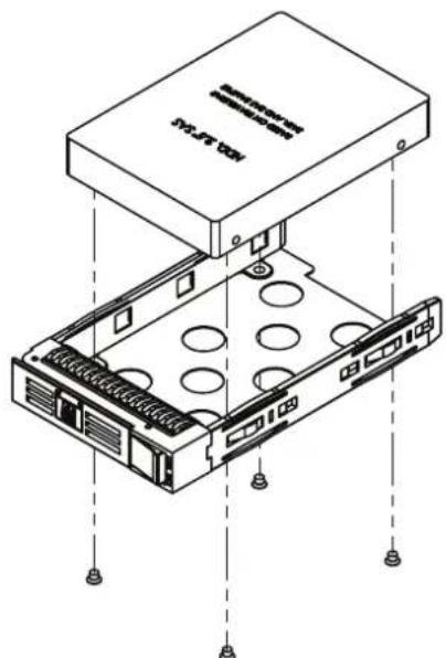
- Slide one SAS/SATA/NVMe disk drive into the tray and affix it in place with 4 screws.
- Return the HDD tray to the chassis, pushing until the handle of the tray returns to the original position. Right-shift the key latch to lock the HDD tray.
- Repeat Steps 1 to 3 to install additional HDDs/SSDs.
natural_image
Technical line drawing of a server rack unit with two inset components (no text or symbols)Figure 2.5 Removing hot-swappable HDD trays/ 移除可热插拔 HDD 托盘 / 移除可热抽换 HDD 托盘
natural_image
Isometric line drawing of a server rack with labeled components and mounting holes (no text or symbols)Figure 2.6 Installing a 2.5" HDD/安装 2.5" 硬盘/安装 2.5" 硬碟
2.4 Installing Sponges/ 安装泡棉 / 安装泡棉
After completing SAS/NVMe cabling, install a pair of sponges into the chassis for a superior cooling effect. The sponges are provided in the accessory box. To install the sponges, refer to the drawing below.
2.5 Slide Rail/滑轨/滑轨

natural_image
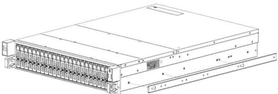
Technical line drawing of a server rack unit with multiple drive bays and ventilation grilles (no text or labels)Figure 2.8 Attaching a side rail to the chassis/ 安装滑轨内轨 / 安装滑轨内轨

natural_image
Technical line drawing of a server rack unit with two external components (no text or symbols)Figure 2.9 Installing a chassis into the rack via the internal side rail/ 安装滑轨外轨 / 安装滑轨外轨
2.5.1 Slide Rail Installation
2.5.1.1 Removing the internal slide rail strip
Pull the slide rail open. Press the rail trigger downwards as shown below. Pull the internal strip of the slide rail outwards.

2.5.1.2 Mount the Internal Strip Onto the Chassis
Either an M4 or MS pan head screw can be used to affix the slide rail. However, the screw head cannot exceed 2.0 mm. Alternatively, the internal slide can be affixed to the chassis via standoffs. Similarly, the head of the standoff cannot exceed 2.0 mm. Use 3 screws or standoffs to attach each side of the slide rail to the chassis.

2.5.1.3 Attach the Slide Rails to the Rack
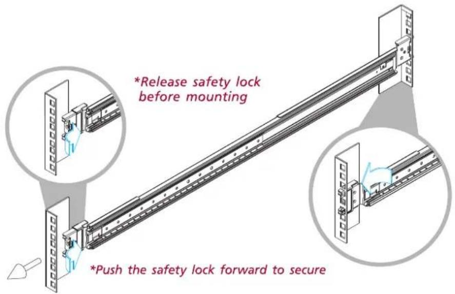
Insert the stag of each rail into the upper and lower square holes of the rack mounting post.
Push the safety lock forward to secure the rack rails. Ensure that the safety lock is unlocked before mounting the rails.
2.5.1.4 Mount the Chassis Into the Rack
Insert the chassis slide rail into the rack as shown in the illustration below. Ensure that the ball retainer is fully open before installing the chassis; otherwise catastrophic damage to the chassis may occur. When returning the chassis to the rack, release the slide from the locked position by pressing the slide trigger downwards.
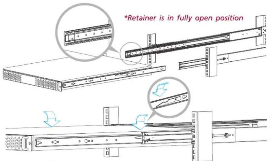
*Press trigger down to release the slides from locking
Chapter 3
Operation
操作
操作
3.1 The Front Panel/ 前面板
The front panel features five LED indicators, a power switch, and a system rest button on the right side and two USB 2.0 ports on the left side. In addition to 24 hot-pluggable HDD trays, the system contains four slots for NVMe support. The specific functions of each feature are described below.
3.1.1 Switch, Buttons, and I/O Interfaces/开关和按钮/開關和按鈕
Power Switch: Press this switch to turn the system power on or off. Select the system shutdown option or press this switch to turn the system ATX power off.
System Reset Button: Press and hold this button for a few seconds to reboot the system.
Two USB 2.0 Ports: These ports can be used to connect a wide range of USB 2.0 devices for data transfers, backups, or input.
Located on the right side of the front panel are five LEDs that serve as indicators of system power and LAN activity. Table 3.1 lists the LED indicator functions.
Note!1. The HDD LED on the front panel only indicates activity from a SATA HDD on the motherboard, for example, the two internal/rear 2.5" SATA drives.
3.1.3 LED Indicators for SAS/SATA HDD Power and Status/
Each SAS/SATA HDD tray is connected to a pair of LED indicators that display the SAS/SATA HDD power and activity status. Table 3.2 lists the LED indicator functions.
When the system power is on and the SAS/SATA HDD is connected, the activity LED emits a steady green light. If the LED does not light up, check the SAS/SATA connection. Alternatively, have a certified technician inspect the related cables in the chassis.
The HPC-8224 SE/SA SKU standard rear plate features 7-slot I/O brackets and a motherboard I/O slot.
natural_image
Back view of a black server rack with front panel, drive bays, and ventilation grilles (no visible text or labels)A grounding screw and washer are located on the lower right of the rear panel. When grounded, this protects the system from damage caused by electric leakage.
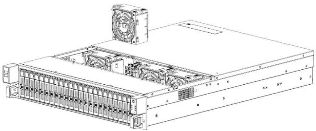
Located behind the SAS backplane are four easy-to-maintain cooling fans.
The design of HPC-8224 facilitates easy replacement of the front system fan.
- Turn off the system.
- Open the middle section of the top cover of the chassis.
- Unplug the system fan by pressing the plastic latch.
- Insert a new fan into the fan bracket.
- Replace the top cover and fasten it in place.
natural_image
Technical line drawing of a mechanical component with no visible text or symbols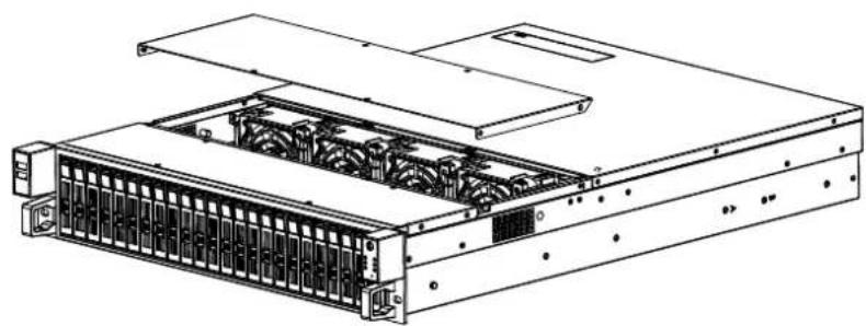
natural_image
Technical line drawing of a server rack unit with internal components (no text or symbols)Figure 3.3: Open the middle section of the top cover/ 打开中顶盖 / 打開中上蓋
natural_image
Technical line drawing of a server rack with cooling fans and drive bays (no text or labels)HPC-8224 requires a 2U-high power supply. Follow the steps below to replace the power supply,
- Unplug the power cord from the power outlet.
- Remove the rear section of the top cover.
- Unplug the 20-pin (or 24-pin) ATX power connector and 4/8-pin +12 V power connector from the motherboard, as well as the power connectors connected to the backplane and SAS expander board.
- Loosen the 4 screws on the rear plate and 2 screws at the bottom of the chassis. Gently remove the chassis (see Figure 3.5).
- Replace the old power supply and fasten the new power supply to the chassis.
- Plug the 20-pin (or 24-pin) ATX power connector and 4/8-pin +12 V power connector to the motherboard. Connect the other power connectors to the backplane, SAS expander board, and peripherals.
- Replace the rear top cover. Plug in the power cord.
natural_image
Technical line drawing of a server rack with multiple drive bays and a central tower (no text or labels visible)Figure 3.5: Replacing the power supply/ 更换电源 / 更换電源
Chapter 4
Backplane and SAS Expander Board
natural_image
Pure electrical circuit lines without any symbolsPort C Port D Port A PortB
Figure 4.2 24 port SAS BP Rear Side Layout (connect to SAS expander board) / 24 port SAS 背板后方配置 (连接至扩展子卡)/ 24 port SAS 背板後方配置 (連接至擴展子卡)
Slot 1/2/3/4 can support NVMe (U.2), SAS 12/6G, or SATA 6G drive.
For Storage server configuration, both "SAS-IN1" and "SAS-IN2" connectors of the SAS expander board can be linked to SAS RAID card. But using with the JBOD kit, the "SAS-IN1" connector in the SAS expander board should be linked to the CN5_IN of the JBOD board, and "SAS-IN2" connector in the SAS expander board must be linked to "CN6_OUT" of the JBOD board
"CN7" and "CN8" connectors of the backplane are designed for NVMe Riser card. For the cabling between NVMe riser card and HPC-8224 backplane, please refer to the following table.
The HPC-8224 platform is equipped with seven low-profile I/O brackets on the rear panel as a default. The system can also support three optional full-height I/O brackets.
The three full-height I/O bracket rear panel kits in the SE and SA SKU differ. Refer to Figure 5.1 for installation.
natural_image
Technical line drawing of a server rack with internal components and a separate rack unit (no text or symbols)Figure 5.1 FH rear panel installation/全高卡后窗的安装 / 全高卡後窗的安裝
Appendix A
Exploded Diagram and Parts List
Please verify specifications before quoting. This guide is intended for reference purposes only.
All product specifications are subject to change without notice.
No part of this publication may be reproduced in any form or by any means, such as electronically, by photocopying, recording, or otherwise, without prior written permission from the publisher.
All brand and product names are trademarks or registered trademarks of their respective companies.
© Advantech Co., Ltd. 2016
www.advantech.com.cn
© Advantech Co., Ltd. 2016
www.advantech.com.tw
© Advantech Co., Ltd. 2016
- HPC-8224
- CLASS 1 LASER PRODUCT KLASSE 1 LASER PRODUKT
- CLASS I LASER PRODUCT KLASS I LASER PRODUKT
- A Message to the Customer/ 致客戶的訊息
- Chapter 1 General Information
- Chapter 2 System Setup
- Chapter 3 Operation
- LED Indicators for SAS/SATA HDD Power and Status/
- Chapter 4 Backplane and SAS Expander Board
- SAS Backplane Layout for SE/SA SKU
- Chapter 5 Rear Panel Full-Height I/O Installation
- Appendix A Exploded Diagram and Parts List
- Installing Sponges/ 安装泡棉 / 安装泡棉
- Slide Rail/滑轨/滑轨
- Slide Rail Installation
- Removing the internal slide rail strip
- Mount the Internal Strip Onto the Chassis
- Attach the Slide Rails to the Rack
- Mount the Chassis Into the Rack
- Chapter 3
- The Front Panel/ 前面板
- Switch, Buttons, and I/O Interfaces/开关和按钮/開關和按鈕
- Chapter 4
- Appendix A
- Exploded Diagram and Parts List
Brand : Advantech
Model : HPC-8224
Category : Server