
AT-PROHD48M-SR - HDMI switch Atlona - Free user manual and instructions
Find the device manual for free AT-PROHD48M-SR Atlona in PDF.


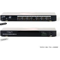
| Product Type | Professional HDMI Matrix Switcher |
| Brand | Atlona |
| Model | AT-PROHD48M-SR |
| Inputs | 4 HDMI inputs |
| Outputs | 8 HDMI outputs |
| Maximum Resolution | 4K@60Hz (3840x2160) |
| HDCP Support | HDCP 2.2 |
| EDID Management | Automatic and manual EDID |
| Control Methods | RS-232, IR, TCP/IP, front panel buttons |
| Audio Support | HDMI embedded audio, digital coaxial output |
| Power Supply | 100-240V AC, 50/60Hz |
| Power Consumption | 30W max |
| Dimensions (W x H x D) | 17.3 x 1.7 x 6.7 in (440 x 43 x 170 mm) |
| Weight | 5.5 lbs (2.5 kg) |
| Mounting | 1U rack-mountable (brackets included) |
| Operating Temperature | 32°F to 104°F (0°C to 40°C) |
| Maintenance | Clean with a dry, soft cloth; keep ventilation slots clear |
| Safety Precautions | Do not expose to moisture; use in a well-ventilated area |
| Repairability | No user-serviceable parts; contact Atlona support for service |
Frequently Asked Questions - AT-PROHD48M-SR Atlona
User questions about AT-PROHD48M-SR Atlona
0 question about this device. Answer the ones you know or ask your own.
Ask a new question about this device
Download the instructions for your HDMI switch in PDF format for free! Find your manual AT-PROHD48M-SR - Atlona and take your electronic device back in hand. On this page are published all the documents necessary for the use of your device. AT-PROHD48M-SR by Atlona.
USER MANUAL AT-PROHD48M-SR Atlona
Service Manual
ATLONA
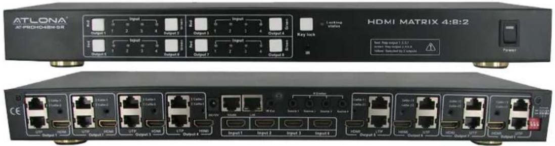
4x8 HDMI MATRIX SWITCH WITH 8 x CAT5 RECEIVERS INCLUDED AT-PROHD48M-SR
AT-PROHD48M-S

natural_image
Two AT-PROHD48M-R network devices with ports and connectors, no visible text or symbols on the device bodies.TABLE OF CONTENTS
- Setting Up CAT5e/6/7 3
- No Power on the Extenders 3
- Image is Bad/Flickers 3
- HDMI Receiver Baluns 4
- IR Issues/Call Back/Operation 4
- EDID Settings 5
- IR Remote Control 7
- No Audio. 7
- HDCP Keys 7
- UPC/ APC Back Ups 7
- Controlling VIA RS232 8
- LAN Control 9
- No Signal on HDMI and CAT5 Out 12
- Using Other Sources Without HDMI 12
SETTING UP CAT5E/6/7
CAT5E or higher is recommended for use with the Atlona AT-PROHD48M-SR. If cables are run in the walls make sure to stay away from light fixtures, electrical boxes, fluorescent lights, and any or other electrical cables to reduce and prevent signal degradation. T568B termination needs to be used for this device.
| Pin | T568A | Pair | T568B | Pair Wire | T568A | Color | T568B | Color Pins on plug face (socket is reversed) |
| 1 | 3 | 2 | tip | white/green stripe | white/orang stripe | |||
| 2 | 3 | 2 | ring | green solid | orange solid | |||
| 3 | 2 | 3 | tip | white/orange stripe | white/green stripe | |||
| 4 | 1 | 1 | ring | blue solid | blue solid | |||
| 5 | 1 | 1 | tip | white/blue stripe | white/blue stripe | |||
| 6 | 2 | 3 | ring | orange solid | green solid | |||
| 7 | 4 | 4 | tip | white/brown stripe | white/brown stripe | |||
| 8 | 4 | 4 | ring | brown solid | brown solid |
If the unit is not powering-on please double check the surge protector/ outlet that the unit is connected to. A Volt Meter can also be used to check the unit and the power supply needs to be outputting 12V DC (110/240v universal).
IMAGE IS BAD/FLICKERS
The image flickers, goes in and out, or there is snow like affect, there are multiple reasons for this issues. Check all the connections HDMI and CAT5E/CAT6 and make sure they are fully connected and are not loose. Check to see the CAT5E/CAT6/CAT7 terminations are fully crimped. CAT5E/CAT6/CAT7 is picking interference from other cables in the wall. Shielded cables are recommended to be run in the walls. CAT5E/CAT6/CAT7 wall plates or CAT5 terminal blocks should not be used as they can also cause interference in the signal; it needs to be connected with cables direct. The CAT5E/CAT6/CAT7 cables should not exceed the distance they are meant to be run at. It is important to use T568B termination on the CAT5E/CAT6/CAT7 cables.
HDMI RECIEVER BALUNS
The RJ45 inputs – please be careful when connecting RJ45 # 1 and # 2 inputs. They absolutely have to match the outputs on the switch. Output # 1 should be connected to Input # 1 and Output # 2 should be connected to Inputs # 2.


When connecting IR receivers and IR emitters, be very careful as if they are reversed the IR Eye will burn-out and also may damage the IR module inside of the switch and Receiver.
When installing IR's, the IR TX (Transmitter) is used on Sources. The eye should be placed over the Source IR eye on most applications. If their signal issues for example, device is not switching, there is lag, the IR is being over flooded. Place the IR TX to the side of the IR eye or up or down to fix the issue. NOTE: the IR on the switch is 36 kilohertz if your source (DVD, blue-ray, cable box is higher the signal will not pass)
The IR RX (Receiver) should be placed in a visible location for the remote to pick up the signal.
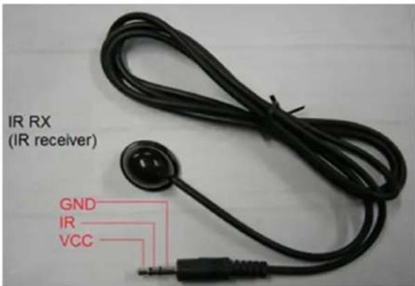
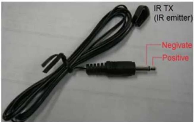
TX – Connects to the Switch
RX – Connects to the HDMI Receivers
IR calls back from remote locations allows controlling the matrix switch as well as nearby sources (such as DVD, AppleTV, Satellite, Cable and etc...).
To enable the function: press the output2 selection button and the key lock button at the same time for about 3 seconds. After all the output1 LEDs and the output2 LEDs flash once, the function is enabled.
To disable the function: press the output2 selection button and the key lock button at the same time for about 3 seconds. After all the output1 LEDS and the output2 LEDS flash twice, the function is disabled. The sequence of "IR1, IR2, IR3, IR4" one-to-one correspond with "HDMI INPUTS1 through 4". When an output chooses certain input, the call-back IR signal of RJ45 on this output will choose the corresponding "IR" port to send the signal out.
For example, OUTPUT1 chooses INPUT3, and then the call-back IR signal of RJ45 on OUTPUT1 will choose "IR 3" to send the signal out.
Note: The switcher can only accept and route IR signal which doesn't exceed 38 KHz. In other words, if you are trying to send IR signal from the remote location though out HDMI receiver and the IR signal is higher than 38 KHz, the IR signal will not pass though.
EDID SETTINGS
(PLEASE READ, IT IS VERY IMPORTANT)
When any of our HDMI/DVI distribution amplifiers are powered on, they will automatically go through an Identification cycle, which means that each output will send an EDID call back request to each one of the display. Once that done, the distribution amplifier will identify the data received and choose the most appropriate EDID setting. The EDID setting chosen will be compatible with all the displays.
The reason why we manage EDID the way we do is because we want to make sure that user will always get signal.
If customer does want to send higher resolution to all the displays which are 1080p and lower resolution to the 720p display, we do offer a up/down scaler box which would be able to scale 1080p down to whatever the TV's native resolution is.
When it comes to our larger matrix switchers, starting at 4x8, we allow users to choose the EDID. User can even choose 1080p and 7.1 Channel Audio, even though some displays may not be compatible. In this case no audio or video will appear on the displays that can't
Support it; however since it is a matrix switch some inputs not always have to be selected and therefore the EDID settings are the way they are.
The functionality of the switch will depend on how you select the DIP Switches below. Please read the instructions and explanations below to understand the purpose of different configurations. There are four DIP switches on the back of the 4x4 matrix switcher. Below you will find the definition of each one of the dip switches.
| Position1 Position2 Position3 Function | ||
| 0 0 0 AUTO EDID MANAGEMENT (note # 1) | ||
| 0 0 1 Copy EDID from output #1 (note # 2) | ||
| 0 1 0 1080P with Stereo Audio (note#3) | ||
| 0 1 1 1080i/720p with Stereo Audio (note#4) | ||
| 1 0 0 1080P with 5.1 Audio (note#5) | ||
| 1 0 1 1080P with 7.1 Audio (note#6) | ||
| 1 1 0 AUTO EDID MANAGEMENT | with one RJ45 (OPTIONAL) (note#7) | |
| 1 1 1 | Copy EDID from output #1 | with one RJ45 (OPTIONAL) (note#8) |
EACH TIME DIP SWITCHES ARE CHANGED; THE ATLONA SWITCH HAS TO POWER CYCLED.
DIP #1: Auto EDID Management (ADM) is a smart function which will allow users to have matrix switch figure out the best and most appropriate EDID.
The way it works: Atlona 4x8 matrix acquires EDID from all the outputs and after processing it, chooses the EDID which will work on all the outputs.
Example #1: User has 8 outputs connected where 6 of the outputs are 1080P TV's only and the other 2 locations are 720P TV's. The Atlona's EDID would be 720P with 2-channel Stereo (because most TV's will only be able to take stereo audio though HDMI input).
Example #2: User has 8 outputs connected, where 6 outputs are 1080P TV's and the remaining are 2 x Surround Sound Receivers (after connected to the TV's for video only). The Atlona's EDID would be 1080P with Stereo or PCM (because most TV's will only take Stereo Audio though HDMI input).
Important Note # Every time new TV's or AVR's are added or replaced, the ADM would have to perform again. The way to do it is to (Simultaneously press and hold the "Output# 1" and "Lock Key" buttons for three seconds)
Remark: If you don't like the Auto EDID Management functions, switcher has some pre-recorded modes which will certainly satisfy you.
DIP #2: If one of your Output devices is a projector or display with a unique resolution, please connected it to the output # 1 and perform the following operation (Simultaneously press "Output# 1" and "Lock Key" buttons). The HDMI output has a higher priority than RJ45 outputs.
DIP #3: Atlona Switcher has a few built-in EDID modes; this mode is for 1080P with Stereo Audio. When this mode is selected and user has some of the displays which are not compatible with 1080p, those displays may not be able to show the image correctly. User might need to use an Atlona HDMI down-scaler for each low resolution display.
DIP #4: Switcher has a few built-in EDID modes; this mode is for 1080i/720p with Stereo Audio. This mode is designed for applications where user has a mix of displays 1080p, 1080i, 720p and wants them all to work. This mode will set the resolution to 1080i or 720p on the source.
DIP #5: Switcher has a few built-in EDID modes; this mode is for 1080p with 5.1 Digital Audio. This mode is designed for applications where user has AV Receivers in each remote location which are able to accept Digital Audio from HDMI inputs. If this mode is selected and in even one of the locations user has a TV without an AV receiver, the TV might “mute” or start outputting garbled audio (because most TV’s don’t support digital audio though HDMI input)
DIP #6: Switcher has a few built-in EDID modes; this mode is for 1080p with 7.1 Digital Audio. This mode is designed for applications where user has AV Receivers in each remote location which are able to accept Digital Audio from HDMI inputs. If this mode is selected and in even one of the locations user has a TV without an AV receiver, the TV might "mute" or start outputting garbled audio (because most TV's don't support digital audio though HDMI input)
DIP #7: This mode is similar to "DIP # 1"; however requires special RJ45 receivers will be required to work on a single RJ45. Ask Atlona sales representative for this option prior purchasing the switch.
DIP #8: This mode is similar to "DIP # 2"; however requires special RJ45 receivers will be required to work on a single RJ45. Ask Atlona sales representative for this option prior purchasing the switch.
IR REMOTE CONTROL

The AT-PROHD48M-SR comes with 32 button IR remote control, which could be used to control the switcher when pointing at it or controlling the switcher from a remote location by pointing the remote control to the IR Eye connected to the HDMI receiver.
For users who would like to use a 3rd part IR remote control or IR remote system, we recommend either learning IR codes off the remote or copying and pasting the IR HEX code into the remote control software. The file with HEX codes could be found on Atlona website under downloads for AT-PROHD48M-SR.
There are 2 scenarios which codes to use:
- User will need to learn all 32 x codes in order to control each location when pointing at the switcher
- User will only need to learn 4 x codes if there will be a separate remote for each remote location
NO AUDIO
There is no audio on the TV or receiver. Set the sources to PCM. Please refer to EDID learning section. Double check all HDMI and CAT5/6/7 connections.
HDCP KEYS
AT-PROHD48M-SR is capable of multiplying the HDCP key to as many outputs as needed, therefore even your source is only able to output 1 x HDCP, the Atlona box will still be able to display the image on 8 displays. This is a very commonly asked question. How do we manage HDCP? Well, a lot of companies do it differently. Some companies use the HDCP keys from sources and pass them over to displays; however this method would be the simplest because there is no software is required, but in the same time most sources have very limited amount of keys. For example if cable box only has one key than only one display can show the signal. Atlona does it differently, we use one key and copy that key to all the outputs (decryption/encryption is being done by Silicon Image chip-sets and therefore we don't see it). This allows user to use a sources with any amount of key's even one and display it on as many as 380 displays at the same time.
The way Atlona does it require a lot of software writing and it is a very hard way of doing it; however we think that it is very important that user is capable of viewing as many displays as needed and not limited to capabilities of the sources.
UPC/APS BACK UPS
The UPC/ APC back ups are meant to be used with computers and servers. They have been used in the AV environment, but we advise against using them. They are not meant to be used with A/V equipment. The solution would be to get dedicated surge protectors or power filters.
CONTROLLING VIA RS232
RS232 Control:
Baud Rate: 9600 bps
Data bits: 8 bits
Parity: None
Stop bits: 1 bit
Flow control: None
RS232 Cable Wiring:
| AT-PROHD48M-SR Controller | |
| Pin Definition | Pin Definition |
| 1 NC 1 NC |  |
| 2 Tx 2 Rx | |
| 3 Rx 3 Tx | |
| 4 NC 4 NC | |
| 5 GND | GND |
| 6 NC 6 NC | |
| 7 NC 7 NC | |
| 8 NC 8 NC | |
| 9 NC 9 NC | |
Note: ‘ ↙’ is carriage return.
| OUTPUT | COMMAND | ACTION |
| < | cir 61 √ | Output 1 select Input previous |
| > | cir 60 √ | Output 1 select Input next |
| Output 1 | cir 09 √ | Output 1 select Input1 |
| cir 1D √ | Output 1 select Input2 | |
| cir 1F √ | Output 1 select Input3 | |
| cir 0D √ | Output 1 select Input4 | |
| < | cir 63 √ | Output 2 select Input previous |
| > | cir 62 √ | Output 2 select Input next |
| Output 2 | cir 19 √ | Output 2 select Input1 |
| cir 1B √ | Output 2 select Input2 | |
| cir 11 √ | Output 2 select Input3 | |
| cir 15 √ | Output 2 select Input4 | |
| < | cir 65 √ | Output 3 select Input previous |
| > | cir 64 √ | Output 3 select Input next |
| Output 3 | cir 17 √ | Output 3 select Input1 |
| cir 12 √ | Output 3 select Input2 | |
| cir 59 √ | Output 3 select Input3 | |
| cir 08 √ | Output 3 select Input4 | |
| < cir 67 Output 4 select Input previous | ||
| > cir 66 Output 4 select Input next | ||
| Output 4 | cir 50 Output 4 select Input1 | |
| cir 55 Output 4 select Input2 | ||
| cir 48 Output 4 select Input3 | ||
| cir 4A Output 4 select Input4 | ||
| < cir 69 Output 5 select Input previous | ||
| > cir 68 Output 5 select Input next | ||
| Output 5 | cir 5E Output 5 select Input1 | |
| cir 06 Output 5 select Input2 | ||
| cir 05 Output 5 select Input3 | ||
| cir 03 Output 5 select Input4 | ||
| < cir 6B Output 6 select Input previous | ||
| > cir 6A Output 6 select Input next | ||
| Output 6 | cir 47 Output 6 select Input1 | |
| cir 07 Output 6 select Input2 | ||
| cir 40 Output 6 select Input3 | ||
| cir 02 Output 6 select Input4 | ||
| < cir 6D Output 7 select Input previous | ||
| > cir 6C Output 7 select Input next | ||
| Output 7 | cir 18 Output 7 select Input1 | |
| cir 44 Output 7 select Input2 | ||
| cir 0F Output 7 select Input3 | ||
| cir 51 Output 7 select Input4 | ||
| < cir 6F Output 8 select Input previous | ||
| > cir 6E Output 8 select Input next | ||
| Output 8 | cir 0A Output 8 select Input1 | |
| cir 1E Output 8 select Input2 | ||
| cir 0E Output 8 select Input3 | ||
| cir 1A Output 8 select Input4 | ||
LAN CONTROL
(Note: Use the cross UTP cable to connect with PC, or use direct cable to connect to the Ethernet switcher)
When running NETCTL for the first time, it will create a file called 'NETCTL.TXT'. This file will contain information for the matrix switch such as MAC address, IP address, and device name.
- Unzip and run the NETCTL application. It will automatically search for any connected devices and display its IP address. Hitting the button "Read Device" will change the IP address to its device name.

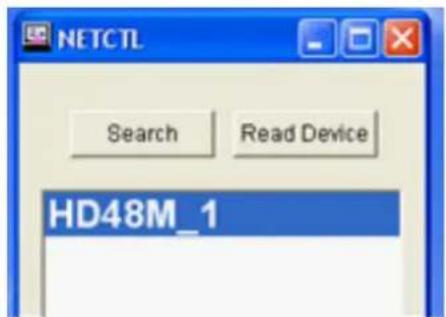
- To Rename; Right Click on the IP Address click "Rename"

- Double Click on the device name or right-click and hit 'open'. A Web Browser window will open with the log in page. The default password is "000000000". After you have entered the password click the 'Login' button. You should now be logged into the Control page.


The Right side is to control the device. The left side shows which input is on which output.
- When 'Assign IP' is displayed, this means that the device has not assigned IP automatically. Double click on 'Assign IP', you can now assign an IP for the Matrix.

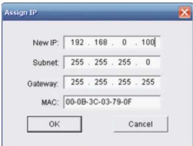
Click OK after assigning new IP, it will then return you to the previous window.
Click 'Search' and then 'Read Device'. The device should now be seen correctly.
NO SIGNAL ON HDMI AND CAT5 OUT
In certain applications some sources will have a hard time passing EDID through matrix switchers.
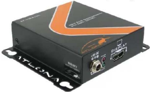
USING OTHER SOURCES WITHOUT HDMI
The solution to it is to contact Atlona for a conversion box to convert any signal you might have to HDMI. Atlona offers a wide variety of conversion boxes specifically designed for application such as this.
AT-HD580: Atlona Composite + S-Video + Dual HDMI input Scaler

The Atlona AT-HD580 is a unique Scaler unit designed to upscale any Standard definition and High definition video signals to an HDMI output. The AT-HD580 takes Composite AV, S-Video with Audio and Dual HDMI inputs and scales all of the above signals to High Resolution HDMI output.
AT-HD600: Atlona 10-input Switcher / Scan Converter with Single HDMI (1.3) Output with 3D Support
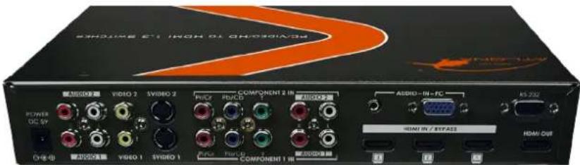
The Atlona AT-HD600 is a 10-input switcher with a single HDMI output. The Atlona switcher is able to switch and convert any of the 2 x composite, 2 x S-Video, 2 x component video, 1 x VGA and 3 x HDMI to a single HDMI output. The HD600 can be controlled though IR remote or RS232
AT-HD560: Atlona Pal HDMI to NTSC HDMI Converter 1080p

Atlona AT-HD560 is an advanced HDMI to HDMI Scaler Box. It accepts HDMI input with a separate to slink or analog audio and scales it to HDMI output (at a number of selectable resolutions and frequencies) with additional to slink and analog audio output.
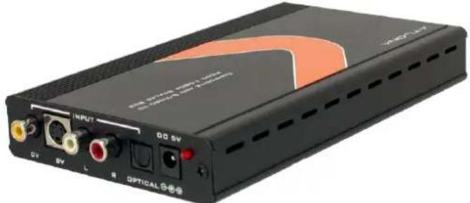
AT-HD520: Atlona Video and S-Video + Audio to HDMI Converter Scaler up to 1080p
natural_image
Black electronic device with labeled ports and indicator lights (no readable text or symbols beyond labels)The Atlona AT-HD520 is designed to upscale analog video signal from Composite or S-Video input sources to digital HDMI output with wide-range of HDTV and PC resolutions; up to 1080p. The Atlona Scaler is also capable of converting Pal to NTSC or NTSC to Pal.
AT-HD530: Atlona HDMI/DVI to Composite and S-Video Down-Converter

The Atlona AT-HD530 is designed to down-convert HDMI or DVI digital signal from PC, Mac, GPS System, Apple TV, Camcorder or Video Game to Analog S-Video or Composite Video with Audio. The AT-HD530 is featured with HDMI/DVI loop-out.
AT-HD500: Atlona PC / Laptop to HDMI Converter with built-in Scaler up to 1080p

natural_image
Black audio optical device with visible ports and connectors (no readable text or symbols)The Atlona AT-HD500 is designed to take video signal from PC or Laptop and upscale it to digital HDMI output of wide-range HDTV and PC resolutions, up to 1080p or WUXGA (1920x1200).
AT-HD570: Atlona HDMI (1.3) Audio De-Embedder with 3D Support

The Atlona AT-HD570 is a professional quality HDMI (1.3) Audio De-Embedder. Unit is capable of accepting an HDMI input signal and de-embeds the audio signal to either Optical or Multi-Channel audio outputs.
AT-COMP-HDMI: Atlona Component Video with Optical to HDMI Converter

Atlona component with digital audio to HDMI converter, converts analog YPrPb or YCrCb and audio to digital HDMI format. It allows you to connect the component output from DVD or Set-Top-Box to digital HDMI input of HD ready plasmas, LCD's or DLP TV's. Supports high resolution up to 1080p.
For more conversion options please click here:
http://www.atlona.com/Converters-with-HDMI-output/




- ATLONA
- TABLE OF CONTENTS
- SETTING UP CAT5E/6/7
- IMAGE IS BAD/FLICKERS
- HDMI RECIEVER BALUNS
- TX – Connects to the Switch
- RX – Connects to the HDMI Receivers
- EDID SETTINGS
- (PLEASE READ, IT IS VERY IMPORTANT)
- IR REMOTE CONTROL
- NO AUDIO
- HDCP KEYS
- UPC/APS BACK UPS
- CONTROLLING VIA RS232
- RS232 Control:
- LAN CONTROL
- NO SIGNAL ON HDMI AND CAT5 OUT
- USING OTHER SOURCES WITHOUT HDMI
- AT-HD570: Atlona HDMI (1.3) Audio De-Embedder with 3D Support
- AT-COMP-HDMI: Atlona Component Video with Optical to HDMI Converter
Brand : Atlona
Model : AT-PROHD48M-SR
Category : HDMI switch