
VTrak J830SD - Disk array Promise Technology - Free user manual and instructions
Find the device manual for free VTrak J830SD Promise Technology in PDF.


| Product Type | Disk Array / Storage Enclosure |
| Form Factor | 3U Rackmount |
| Supported Drives | Up to 16 x 3.5" SAS/SATA HDD or SSD |
| Drive Interface | SAS 3.0 (12 Gb/s) |
| Expansion | Daisy-chain via SAS (up to 4 enclosures) |
| RAID Support | Hardware RAID 0, 1, 5, 6, 10, 50, 60 |
| Management | Web-based PBM (PromiseBay Management), CLI, LCD panel |
| I/O Modules | Dual redundant I/O controllers (SAS) |
| Cooling | Redundant, hot-swappable fan modules |
| Power Supply | Dual redundant, hot-swappable (80 PLUS Gold) |
| Power Consumption | Typical 350W, Max 500W |
| Input Voltage | 100-240V AC, 50-60Hz |
| Dimensions (HxWxD) | 5.2 in x 17.6 in x 19.6 in (13.2 cm x 44.7 cm x 49.8 cm) |
| Weight (empty) | ~45 lb (20.4 kg) |
| Operating Temperature | 5°C to 40°C (41°F to 104°F) |
| Certifications | CE, FCC, UL, RoHS |
| Key Features | Hot-swap drives, dual-path SAS, error recovery, predictive drive failure |
| Maintenance | Firmware upgrade via web GUI; replaceable fan and PSU modules |
| Safety | Overvoltage protection, thermal monitoring, secured rackmount kit |
| Spare Parts | PSU, fan, I/O module, controller battery backup unit (optional) |
Frequently Asked Questions - VTrak J830SD Promise Technology
User questions about VTrak J830SD Promise Technology
0 question about this device. Answer the ones you know or ask your own.
Ask a new question about this device
Download the instructions for your Disk array in PDF format for free! Find your manual VTrak J830SD - Promise Technology and take your electronic device back in hand. On this page are published all the documents necessary for the use of your device. VTrak J830SD by Promise Technology.
USER MANUAL VTrak J830SD Promise Technology
natural_image
Five black star shapes arranged horizontally: five with radiating lines, one with a starburst, two with a starburst and one with a pentagram (no text or symbols)

natural_image
Collection of black geometric shapes including stars, diamonds, and floral patterns (no text or symbols)Version 1.1
Copyright
© 2009 Promise Technology, Inc. All Rights Reserved.
Copyright by Promise Technology, Inc. (Promise Technology). No part of this manual may be reproduced or transmitted in any form without the expressed, written permission of Promise Technology.
Trademarks
Promise, and the Promise logo are registered in U.S. Patent and Trademark Office. All other product names mentioned herein may be trademarks or registered trademarks of their respective companies.
Important data protection information
You should back up all data before installing any drive controller or storage peripheral. Promise Technology is not responsible for any loss of data resulting from the use, disuse or misuse of this or any other Promise Technology product.
Notice
Although Promise Technology has attempted to ensure the accuracy of the content of this manual, it is possible that this document may contain technical inaccuracies, typographical, or other errors. Promise Technology assumes no liability for any error in this publication, and for damages, whether direct, indirect, incidental, consequential or otherwise, that may result from such error, including, but not limited to loss of data or profits.
Promise Technology provides this publication “as is” without warranty of any kind, either express or implied, including, but not limited to implied warranties of merchantability or fitness for a particular purpose.
The published information in the manual is subject to change without notice. Promise Technology reserves the right to make changes in the product design, layout, and driver revisions without notification to its users.
This version of the Product Manual supersedes all previous versions.
Recommendations
In this Product Manual, the appearance of products made by other companies, including but not limited to software, servers, and disk drives, is for the purpose of illustration and explanation only. Promise Technology does not recommend, endorse, prefer, or support any product made by another manufacturer.
Contents
Chapter 1: Introduction to VTrak .....1
About This Manual....1
VTrak Overview 2
Architectural Description 4
Features and Benefits 5
Specifications 6
Drives and Ports 6
Operating System Support 6
Power 6
Environmental....7
Dimensions 7
Safety Standards 7
Warranty and Support 8
CE Statement 8
FCC Statement 8
GOST-R Statement 8
IRAM Statement 8
KCC Statement ....8
Chapter 2: Installation .....9
Unpacking the VTrak 9
Mounting the VTrak in a Rack 11
Installing Disk Drives 14
Drive Slot Numbering 14
Installing 3.5-inch Disk Drives .....15
Installing 2.5-inch Disk Drives .....17
Making Data Connections 19
Basic DAS Connection .....19
Cascading DAS Connection 20
Redundant Cascading DAS Connection .....21
Setting Up Serial Cable Connections .....23
Connecting the Power 24
Setting Up the CLI Connection .....25
Chapter 3: Management .....27
Front Panel LEDs .....27
Drive Carrier LEDs 28
Power Supply LED 29
I/O Module LEDs 30
Shutting Down and Restarting the VTrak 31
Chapter 3: Management, cont.
Command Line Interface ....32
Command Set 32
Enclosure Command 32
Making Enclosure Settings 35
Factorydefaults Command ....37
Help Command ....37
Link Command ....38
Route Command ....41
Uptime Command 42
? Command 42
Chapter 4: Support .....43
Frequently Asked Questions 43
Contacting Technical Support 44
Limited Warranty 47
Returning the Product For Repair 49
Appendix A: Miscellaneous .....51
Adding a Second I/O Module .....51
Replacing a Power Supply Fan ....52
Removing the Fan Assembly .....53
Installing the Fan Assembly ....55
Index. 57
Chapter 1: Introduction to VTrak
This chapter covers the following topics:
- About This Manual (below)
• VTrak Overview (page 2)
• Architectural Description (page 4)
• Features and Benefits (page 5) - Specifications (page 6)
Thank you for purchasing a Promise VTrak J830s or J630s external disk subsystem.
About This Manual
This Product Manual describes how to setup, use, and maintain the VTrak J830s or J630s subsystem. It also describes how to use the built-in command-line interface (CLI) software.
This manual refers to the VTrak in the following interchangeable terms:
- VTrak Subsystem
• V T r a k U n i t - VTrak Enclosure
This manual includes a full table of contents, index, chapter task lists and numerous cross-references to help you find the specific information you are looking for.
Also included are four levels of notices:

Note
A Note provides helpful information such as hints or alternative ways of doing a task.

Important
An Important calls attention to an essential step or point required to complete a task. Important items include things often missed.

Caution
A Caution informs you of possible equipment damage or loss of data and how to avoid them.

Warning
A Warning notifies you of probable equipment damage or loss of data, or the possibility of physical injury, and how to avoid them.
VTrak Overview
The Promise VTrak J830s and J630s are optimized for organizations deploying cost-effective small-to-medium application clusters, disk-to-disk backup and midrange storage solutions.
Figure 1. VTrak J830s front view
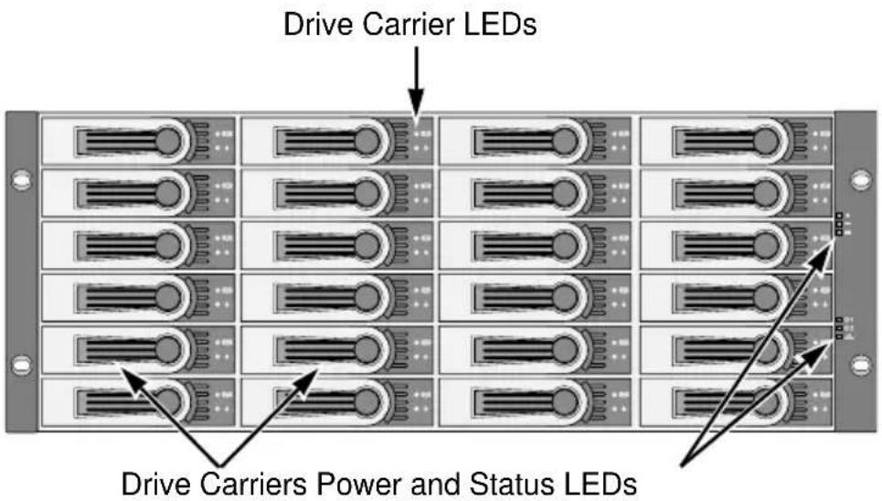
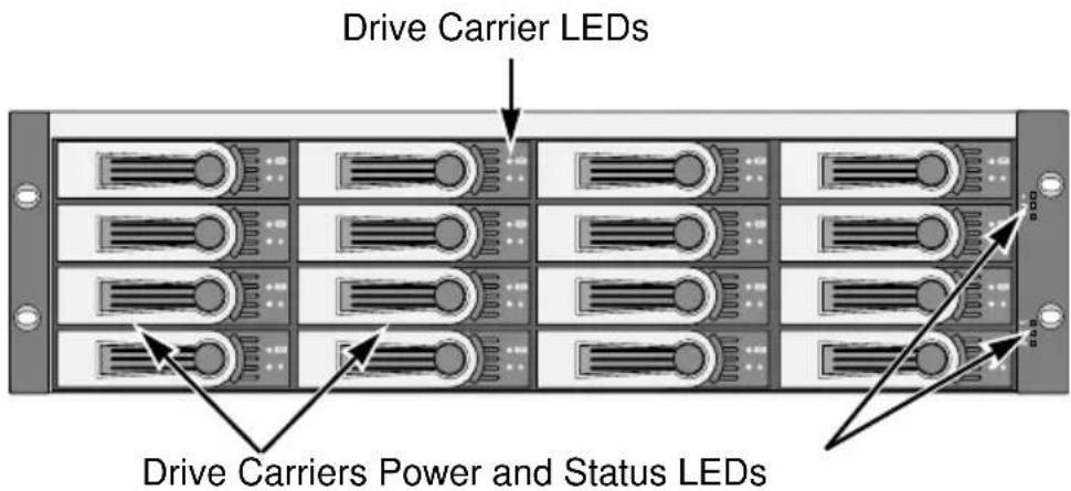
Figure 2. VTrak J630s front view
The dual 6Gb SAS host interface ports offer the ease of management and performance required by companies running popular departmental and back-office applications including file/print, e-mail, database and Web services.
Figure 3. VTrak J830s rear view

Figure 4. VTrak J630s rear view

The two external SAS ports provide the needed connectivity and bandwidth for large capacity solutions requiring multiple JBOD boxes cascaded together while still providing dual server support and host port failover or aggregation.
Architectural Description
The VTrak J830s packs up to 24 drives per system, offering industry-leading capacity in just 4U of standard 19-inch rack space. The VTrak J630s supports up to 16 drives per system, in just 3U of standard 19-inch rack space. The J830s and J630s unit's compact form factor maximizes density, increasing capacity per unit of rack space.
Multiple J830s and J630s systems can also be connected to the same server using standard SAS features to deliver massive storage to capacity hungry applications such as disk-to-disk backup, media archiving, video surveillance and compliance storage
Promise has designed the J830s and J630s chassis to be fully compatible with all future Promise external storage products. By using the same chassis, drive carriers, and cooling units, upgrading the RAID controllers and JBOD modules is fast and simple.
With the VTrak J830s and J630s, Promise has dramatically narrowed the gap between simple fault tolerance and No Single Point of Failure. The VTrak J830s and J630s use a fully redundant, hot-swappable design and continuously monitors all system components. It can withstand failures to disks, power supplies, and I/O modules without interrupting system operation.
Features and Benefits
| Feature Benefit | |
| 4U or 3U 19-inch wide enclosure Installs easily in any standard rackmount. | |
| Supports Serial Attached SCSI disk drives | Allows you to use the new dual-port SAS disk drives. |
| Supports Serial ATA disk drives Allows you to use your legacy SATA disk drives. | |
| Hot-swap feature for drive carriers, I/O modules, and power supplies | Allows a defective component to be replaced without interrupting data accessibility to the host system. |
| Supports SBB 2.0 standard Allows controller inter-connectability with controllers of the same capacity from other manufacturers. | |
| Tool-less field-replaceable units (FRUs) | All FRUs can be replaced without tools, saving time and effort for support personnel. |
| Complete cable-less design All components easily plug directly into boards. No cables to complicate setup or maintenance. | |
| Redundant, hot-swappable power supplies | Load sharing and full operation even with a failed power supply. |
| Dual, active/active I/O Modules High level of availability even with a failed I/O module. | |
| Two SAS ports per I/O module Enables host access or cascading JBOD subsystems. | |
| Command-line interface Control and monitoring with simple, straightforward interface. | |
| Management through in-band SAS or serial port | Choice of local or network management options |
| Compatible with leading SAS HBA and RAID cards | Works the first time with all major SAS HBA or RAID adapters |
Specifications
Drives and Ports
Drive Bay Count: J830s, 24 drives. J630s, 16 drives.
Supported Disk Drive Interfaces:
Serial Attached SCSI (SAS), 6Gb/s and 3Gb/s
Serial ATA (SATA), 3Gb/s and 1.5Gb/s
External I/O Ports: SAS host port and SAS expansion port.
Operating System Support
• Windows Vista, Business, Enterprise, or Ultimate
- Windows 2008 Server
- Windows 2003 Server
- Windows XP Professional
- Windows 2000
- RedHat Linux
- SuSE Linux
The list above refers to both 32-bit and 64-bit versions of the OS in the Host PC or server. The actual OS support depends upon your SAS HBA or RAID adapter. Check your SAS HBA or RAID adapter user documentation.
Power
| VTrak Model | Input Voltage | Current | Power Consumption | Thermal Output |
| J830s | 110V 4.20 | 6A 458W 156 | 3.1 BTU/Hr | |
| 220V 2.12 | 8A 450W 153 | 5.8 BTU/Hr | ||
| J630s | 110V 2.97 | 2A 326W 111 | 2.6 BTU/Hr | |
| 220V 1.75 | 6A 372W 126 | 9.6 BTU/Hr | ||
| All figures include disk drives. | ||||
Power Supply:
J830s, Dual 750W, 100–240 VAC auto-ranging, 50–60 Hz, dual hot swap and redundant with PFC, N+1 design.
J630s, Dual 580W, 100–240 VAC auto-ranging, 50–60 Hz, dual hot swap and redundant with PFC, N+1 design.
Environmental
Operating Temperature: 10° to 40°C (10° to 35°C recommended for SAS drives)
Non-operating Temperature: -40° to 60°C
Operating Humidity: 8% to 80% non-condensing.
Non-operating Humidity: 8% to 95% non-condensing
Operating Vibration: 0.3g (0 to peak), swept sine, 5 to 500Hz, 12 octave per minute.
Non-operating Vibration: 1g (0 to peak), swept sine, 5 to 500Hz, 12 octave per minute.
Operating Shock: 5g amplitude, 11ms duration.
Non-operating Shock: 10g amplitude, 11ms duration.
Altitude: 0 to 2100 m (7000 ft) or 0 to 3000 m (10,000 ft) at less than 35°C
Acoustics: 50 decibels, A-weighted (sound pressure) with fans operating at low speed.
Dimensions
Enclosure (height x width x depth):
J830s, 13.1 x 44.7 x 56.1 cm (5.2 x 17.6 x 22.1 in)
J630s, 8.8 x 44.7 x 56.1 cm (3.5 x 17.6 x 22.1 in)

Note
At the time of this writing, weight information was still preliminary.
Net Weight:
J830s, 30.5 kg (67.2 lb) without drives, 38.5 kg (84.9 lb) with 24 drives, assuming 0.5 kg (1.1 lb) per drive.
J630s, 26.5 kg (58.4 lb) without drives, 32.5 kg (71.7 lb) with 16 drives, assuming 0.5 kg (1.1 lb) per drive.
Gross Weight (including carton):
J830s, 37.5 kg (82.7 lb) without drives.
J630s, 33.0 kg (72.8 lb) without drives.
Safety Standards
UL1950, EN60950, CSA 950; BSMI, VCCi, cUL, TUV, MIC
Warranty and Support
Warranty: Three years complete system limited warranty.
Support: 24x7 email and phone support (English only). 24x7 access to Promise support site to download firmware, utilities, and manuals; to obtain compatibility information and knowledge bulletins.
CE Statement
Warning: This is a class A product. In a domestic environment this product may cause radio interference in which case the user may be required to take adequate measures.
FCC Statement
This device complies with Part 15 of the FCC Rules. Operation is subject to the following two conditions: (1) this device may not cause harmful interference, and (2) this device must accept any interference received, including interference that may cause undesired operation.
GOST-R Statement
Chapter 2: Installation
- Unpacking the VTrak (below)
- Mounting the VTrak in a Rack (page 11)
- Installing Disk Drives (page 14)
- Making Data Connections (page 19)
- Setting Up Serial Cable Connections (page 23)
- Connecting the Power (page 24)
- Setting Up the CLI Connection (page 26)
Please read through these instructions completely before you begin. You might need additional items to complete your installation.
Unpacking the VTrak
The VTrak J830s or J630s box contains the following items:
- VTrak Unit
- Quick Start Guide
- RJ11-to-DB9 serial data cables (2)
• 1.0m (3.3 ft) SFF-8088 4X to 4X external SAS cable Dual-controller models, 2 Single-controller models, 1
- Screws for disk drives (J830s: 106, including 10 spares) (J630s: 70, including 6 spares)
- Left and right mounting rails
• 1.5m (4.9 ft) Power cords (2)
• CD with Product Manual and Quick Start Guide

Warning
The electronic components within the VTrak are sensitive to damage from Electro-Static Discharge (ESD). Observe appropriate precautions at all times when handling the VTrak or its subassemblies.

Caution
VTrak supports disk drive hot-swapping. To avoid hand contact with an electrical hazard, do not remove more than one drive carrier a time.
Notices

Warning to User: This is Class A ITE product which might cause radio frequency interference if it is used in a residential environment. In such case, the user would be requested to adopt certain appropriate measures.
A 급 기기 (업무용 방송통신기기)
Figure 1. VTrak J630s front view. The J830s is similar

Figure 2. VTrak J630s rear view. The J830s is similar

Mounting the VTrak in a Rack

Cautions
- At least two persons are required to safely lift, place, and attach the VTrak unit into a rack system.
- Do not lift or move the VTrak unit by the handles, power supplies or the controller units. Hold the subsystem itself.
- Do not install the VTrak unit into a rack without rails to support the subsystem.
- Only a qualified technician who is familiar with the installation procedure should mount and install the VTrak unit.
- Be sure all switches are OFF before installing the VTrak unit or exchanging components.
- Mount the rails to the rack using the appropriate screws and flange nuts, fully tightened, at each end of the rail.
- Do not load the rails unless they are installed with screws as instructed.
- The rails that ship with the Promise VTrak unit are designed to safely support that Promise VTrak unit when properly installed. Additional loading on the rails is at the customer's risk.
- Promise Technology, Inc. cannot guarantee that the mounting rails will support your Promise VTrak unit unless you install them as instructed.

Note
To lighten the VTrak enclosure, remove the power supplies. Replace the power supplies after the VTrak unit is mounted in your rack.
The J830s and J630s subsystems install to the rack using the supplied mounting rails. You can also use your existing rails.
Figure 3. VTrak J630s mounted in a rack with the supplied rails

To install the VTrak subsystem into a rack with the supplied mounting rails:
- Check the fit of the mounting rails in your rack system. See page 13, Figure 4.
- Adjust the length of the mounting rails as needed.
The rear rail slides inside the front rail. The rail halves are riveted together and use no adjustment screws.
- Attach the mounting rail assemblies to the outside of the rack posts, using the attaching screws and flange nuts from your rack system.
Be sure the front rail support is on the bottom facing inward.
The alignment pins fit into the rack holes above and below the attaching screws.
Use the attaching screws and flange nuts from your rack system. Tighten the screws and flange nuts according to your rack system instructions.
- Place the VTrak subsystem onto the rails.
- Secure the VTrak subsystem to the rack.
One screw each side, upper hole only. Use the attaching screws and flange nuts from your rack system. Tighten the screws and flange nuts according to your rack system instructions.
Figure 4. Rack mount assembly diagram
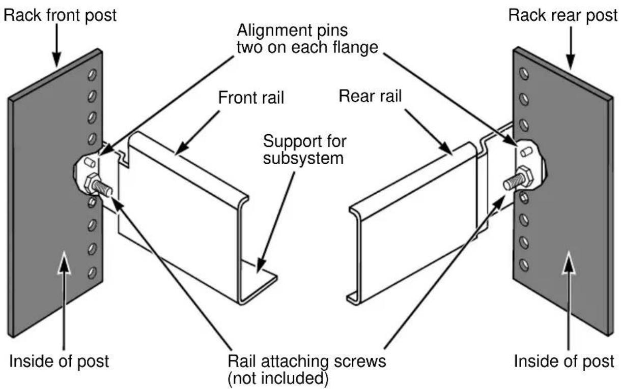
Note that only the front rail has a support for the subsystem.
Installing Disk Drives
You can populate the VTrak enclosure with SAS or SATA disk drives. See the Compatibility List on the Promise Website for complete listings of qualified disk drives.
For optimal performance, install disk drives of the same model and capacity.
Drive Slot Numbering
You can install any suitable disk drive into any slot in the enclosure. The diagrams below show how VTrak's drive slots are numbered.
Figure 5. VTrak J830s drive slot numbering

Figure 6. VTrak J630s drive slot numbering

Install all of the drive carriers into the VTrak enclosure to ensure proper airflow, even if you do not populate all the carriers with disk drives.
Installing 3.5-inch Disk Drives

Important
- If your VTrak has two I/O modules and you are installing SATA disk drives, an AAMUX adapter is required so that both modules can access the SATA disk drive. Obtain AAMUX adapters from Promise Technology, Inc.
- Proper installation ensures adequate grounding and minimizes vibration. Always install the disk drives using all four screws.
To install your 3.5-inch disk drives:
- Remove a disk drive carrier.
- Carefully lay the drive into the drive carrier at the front, so that the screw holes on the sides line up.
If you are installing a AAMUX adapters and SATA disk drives: First attach the adapter to the drive. Then install the mounting screws. See page 16, Figure 7.
-
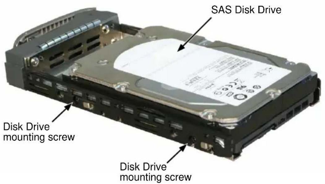
Insert the screws through the holes in the sides of the drive carrier and into the disk drive. See page 16, Figures 7 and 8.
-
For the disk drive, install only the screws supplied with the VTrak.
- For the adapter, install only the screws supplied with the adapter.
• Install four screws per drive.
• Install two screws per adapter. -
Snug each screw. Be careful not to over tighten.
-
Reinstall the drive carrier into the VTrak chassis.
-
Repeat steps 2 through 4 until all of your disk drives are installed.

Caution
VTrak supports disk drive hot-swapping. To avoid hand contact with an electrical hazard, do not remove more than one drive carrier a time.
Figure 7. Drive carrier with 3.5-inch SATA disk drive and AAMUX

Figure 8. Drive carrier with 3.5-inch SAS disk drive
Installing 2.5-inch Disk Drives

Cautions
- Always use mounting brackets to install 2.5-inch disk drives. Never install disk drives by inserting screws through the bottom of the drive carrier. Obtain mounting brackets and screws from Promise Technology, Inc.
- Hold 2.5-inch disk drives by the edge to prevent damage to the drive.
- VTrak supports disk drive hot-swapping. To avoid hand contact with an electrical hazard, do not remove more than one drive carrier a time.

Important
- If your VTrak has two I/O modules and you are installing SATA disk drives, an AAMUX adapter is required so that both modules can access the SATA disk drive. Obtain AAMUX adapters from Promise Technology, Inc.
- Proper installation ensures adequate grounding and minimizes vibration. Always install the disk drives using all four screws.
To install your 2.5-inch disk drives:
- Attach a bracket to the disk drive. See page 18, Figure 9.
• Install only the screws supplied with the bracket.
• Install two screws per bracket.
- Snug each screw. Be careful not to over tighten.
- Remove a disk drive carrier.
- Carefully lay the drive into the drive carrier at the front, so that the screw holes on the sides line up.
If you are installing a AAMUX adapters and SATA disk drives:
First attach the adapter to the drive. Then install the mounting screws.
-
Insert the screws through the holes in the sides of the drive carrier and into the disk drive. See page 18, Figure 10.
-
For the disk drive, install only the screws supplied with the VTrak.
- For the bracket, install only the screws supplied with the bracket.
- For the adapter, install only the screws supplied with the adapter.
• Install two screws per drive, two screws per bracket, and two screws per adapter.
- Snug each screw. Be careful not to over tighten.
-
Reinstall the drive carrier into the VTrak chassis.
-
Repeat steps 2 through 5 until all of your disk drives are installed.
Figure 9. 2.5-inch disk drive and mounting bracket
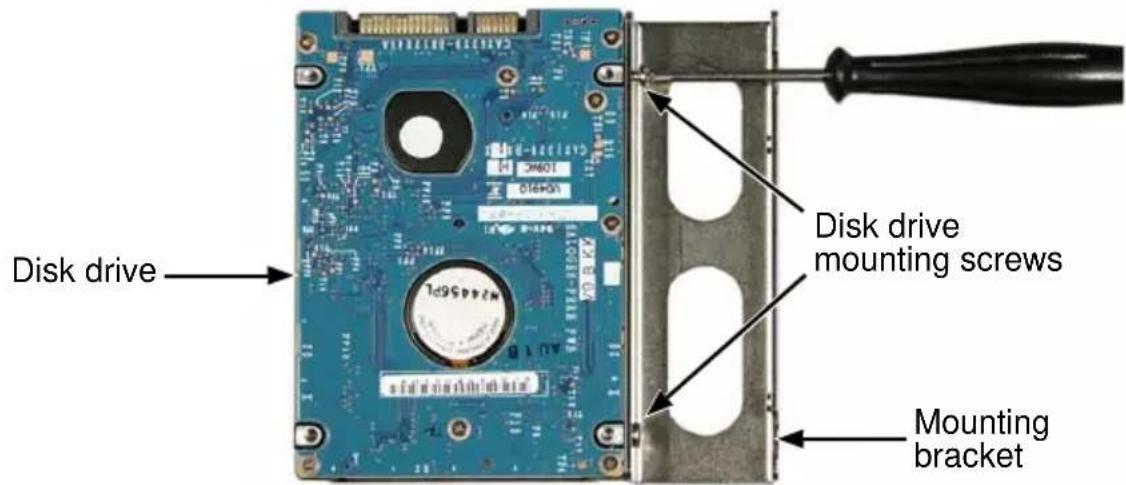
Figure 10. Drive carrier mounting screw locations
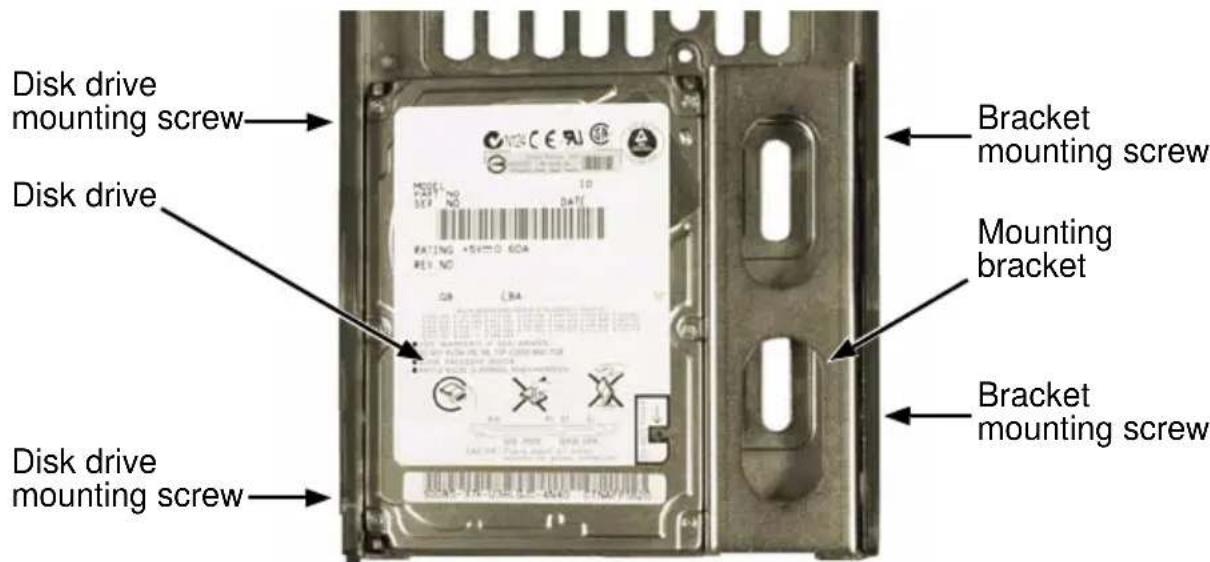
Note: The bracket screws are larger than disk drive screws.
Making Data Connections
You can configure your VTrak JBOD as:
- Basic Direct Attached Storage (DAS) Connection (below)
• Cascading DAS Connection (page 20) - Redundant Cascading DAS Connection (page 21)
Basic DAS Connection
To setup a basic DAS connection:
- You must have a SAS HBA card in the Host PC or server.
- Connect the SAS HBA card in the Host PC to the SAS IN port (with the circle icon) on the VTrak. See Figure 11.
- Use the SFF-8088 4X to 4X external SAS cable supplied with the VTrak.
Figure 11. A basic DAS connection

Host PC or Server
The diagram above shows the VTrak J630s. A connection with the J830s is exactly the same.
This completes data and management connections. Go to "Setting Up Serial Cable Connections" on page 23.
Cascading DAS Connection
To setup a cascading DAS connection:
- Connect the SAS HBA card in the Host PC to the SAS IN port (with the circle icon) on the first VTrak.
See Figure 12. Use a SFF-8088 4X to 4X external SAS cable (supplied with the VTrak).
- Connect the SAS OUT port (with the diamond icon) on the same I/O module of the first VTrak to the SAS IN port (with the circle icon) on the second VTrak.
Be sure to connect circle icon to diamond icon or vice versa.
You can cascade up to four VTrak units in this manner.
You can mix J830s and J630s units as well as J610s and J310s units in the same cascade. Note that Jx10s are 3Gb units and might reduce data throughput.
Figure 12. A cascaded DAS connection

flowchart
graph TD
    A["SAS HBA Card"] --> B["Host PC or Server"]
    B --> C["SFF-8088 external 4X to 4X SAS cable"]
    C --> D["SAS IN circle port"]
    D --> E["SAS OUT diamond port"]
    E --> F["VTrak J630s"]
    F --> G["SAS IN circle port"]
    G --> H["SAS OUT diamond port"]
    H --> I["VTrak J630s"]
    I --> J["SAS IN circle port"]
The diagram on page 20 shows the VTrak J630s. Connections with the J830s are exactly the same.
This completes data and management connections. Go to “Setting Up Serial Cable Connections” on page 23.
Redundant Cascading DAS Connection
To setup a redundant cascading DAS connection:
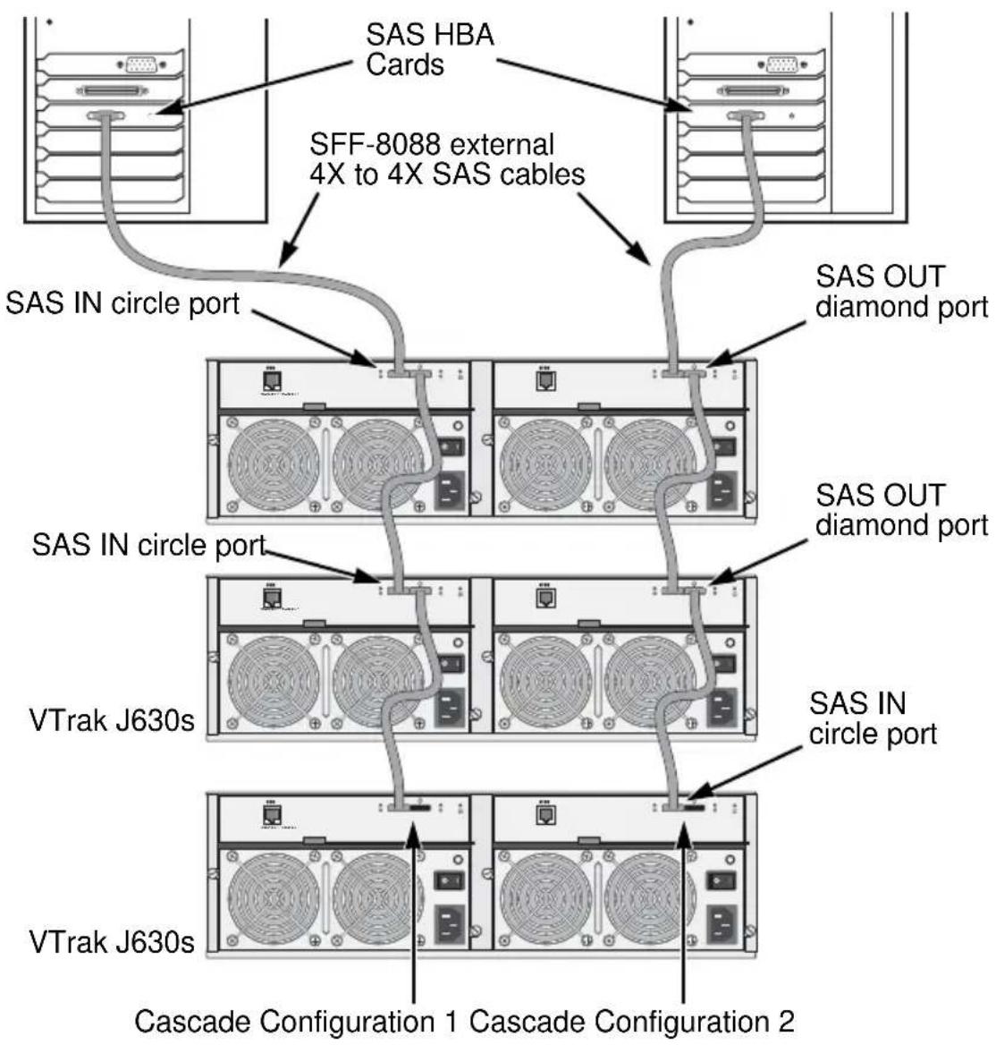
- Connect the SAS HBA card in the first Host PC to the SAS IN port (with the circle icon) on the first VTrak.
See page 22, Figure 13. Use a SFF-8088 4X to 4X external SAS cable (supplied with the VTrak).
- Connect the SAS OUT port (with the diamond icon) on the same I/O module of the first VTrak to the SAS IN port (with the circle icon) on the second VTrak.
- Connect the SAS HBA card in the second Host PC to the SAS IN port (with the circle icon) to the other I/O module on the first VTrak.
- Connect the SAS OUT port (with the diamond icon) on the same I/O module of the first VTrak to the SAS IN port (with the circle icon) of the other I/O module on the second VTrak.
- Connect the remaining VTraks in the same manner.
Be sure to connect circle icon to diamond icon or vice versa.
Do not cross-connect the I/O modules. Maintain a separate cascade configuration from each Host PC or Server to the last VTrak. See page 22, Figure 13.
You can cascade up to four VTrak units in this manner.
You can mix J830s and J630s units as well as J610s and J310s units in the same cascade. Note that Jx10s are 3Gb units and might reduce data throughput.
Figure 13.A redundant cascading DAS connection
flowchart
graph TD
    A["SAS HBA Cards"] --> B["SFF-8088 external 4X to 4X SAS cables"]
    B --> C["SAS IN circle port"]
    B --> D["SAS OUT diamond port"]
    C --> E["VTrak J630s"]
    D --> F["VTrak J630s"]
    E --> G["Cascade Configuration 1"]
    F --> H["Cascade Configuration 2"]
The diagram above shows the VTrak J630s. A connection with the J830s is exactly the same.
This completes data and management connections. Go to “Setting Up Serial Cable Connections” on page 23.
Setting Up Serial Cable Connections
Serial communication enables the Command Line Interface (CLI) on your PC to monitor and control the VTrak JBOD. The CLI is explained in “Setting Up the CLI Connection” on page 26.
The VTrak box includes a RJ11-to-DB9 serial data cable.
To set up a serial cable connection:
- Attach the RJ11 end of the serial data cable to the RJ11 serial connector on the left I/O module on the back of the VTrak.
See Figure 14.
- Attach the DB9 end of the serial data cable to a serial port on the Host PC or Server.
Figure 14. Use the serial connector on the left I/O module
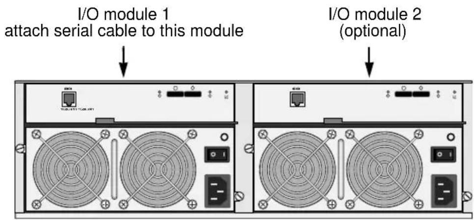
RJ11 Serial Connector

Connecting the Power
VTrak ships with clip assemblies to secure the power cords.
To secure the power cords:
- Insert the barbed end of the band into the hole until it snaps into place.
- Attach the power cord to the power supply.
- Place the clip over the power cord, slide the clip to the end as shown in the Figure below, then squeeze the clip to tighten it.
Figure 15. Securing a power cord with the clip assembly

To reposition or release the clip, pull the tabs as shown.
- Switch on the power supplies.
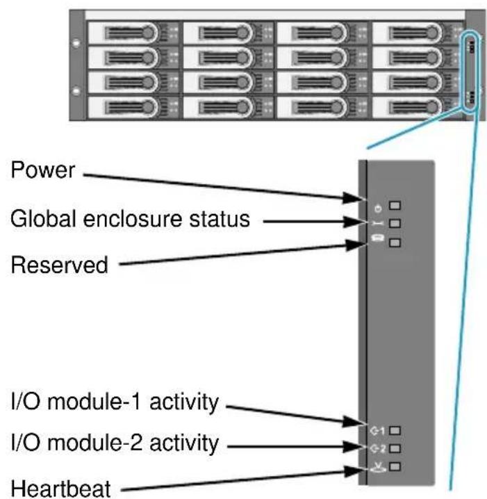
When the power is switched on, the LEDs light up.
When boot-up is finished and the VTrak subsystem is functioning normally:
• Power and Global enclosure status LEDs display green continuously.
- I/O module activity LEDs flash green when there is I/O module activity.
- System heartbeat LED blinks green once every 4 seconds if one I/O module is installed or once every 2 seconds if two I/O modules are installed.
Figure 16.VTrak J630s front panel LED display. The J830s is similar
Generally speaking, if there is a disk drive in the carrier, the Power/Activity LED displays green. If not, the LED remains dark. The Power/Activity LED flashes during drive activity.
The Disk Status LED displays green when the drive has been configured.
Figure 17. Drive carrier LEDs

Setting Up the CLI Connection
The VTrak has a Command Line Interface (CLI) to manage all of its functions, including customization. Access the CLI via your PC's terminal VT100 or ANSI emulation program, such as Microsoft HyperTerminal.
The VTrak must be running and the RJ11-to-DB9 serial data cable connected to the primary I/O module and the Host PC or Server's serial port. See page 23.
To set up the CLI connection:
-
Change your terminal emulation program settings to agree with the following:
-
Bits per second: 115200
- Data bits: 8
- Parity: None
- Stop bits: 1
-
Flow control: none
-
Start your PC's terminal emulation program.
-
Press Enter once to launch the CLI.
The cli> prompt on your screen indicates that you have a connection and the CLI is ready to accept commands.
See "Command Line Interface" on page 32.
Chapter 3: Management
- Front Panel LEDs (below)
- Drive Carrier LEDs (page 28)
• Power Supply LED (page 29)
• I/O Module LEDs (page 30) - Shutting Down and Restarting the VTrak (page 31)
- Command Line Interface (page 32)
Front Panel LEDs
The LEDs on the front panel of the VTrak J830s or J630s unit provide important status information about the subsystem.
When boot-up is finished and the VTrak subsystem is functioning normally:
• Power and Global enclosure status LEDs display green continuously.
- I/O module activity LEDs flash green when there is activity on the SAS ports.
- System heartbeat LED blinks green once every 4 seconds if one I/O module is installed or once every 2 seconds if two I/O modules are installed.
Figure 1. VTrak J630s front panel LED display. The J830s is similar

See the table on the next page for more information.
| LEDs | State | ||||
| Dark | Steady Green | Flashing Green | Amber Red | ||
| Power System Off Normal — — — | |||||
| Global enclosure status | System Off | Normal — | Malfunction – one power supply | Malfunction – both power supplies | |
| I/O module 1 or 2 | No Activity — | Activity — — | |||
| Heartbeat System Off — | Normal* | — — | |||
| * Blinks once every 4 seconds if one I/O module is installed or once every 2 seconds if two I/O modules are installed. | |||||
Drive Carrier LEDs
There are two LEDs on each drive carrier.
Generally speaking, if there is a disk drive in the carrier, the Power/Activity LED displays green. If not, the LED remains dark. The Power/Activity LED flashes during drive activity.
The Disk Status LED displays green when the drive has been configured.
Figure 2. Drive carrier LEDs
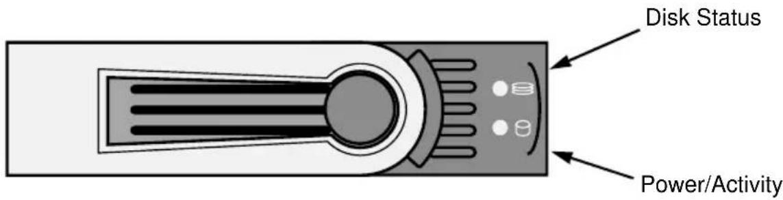
If you have SATA disk drives installed without an AAMUX adapter (see page 16), the Power/Activity LED behavior depends on the specific disk drive.
The Disk Status LED behavior depends on your HBA or RAID controller. See the table on the next page.
| LEDs | State | ||||
| Dark | Steady Green | Flashing Green | Steady Blue | Flashing Blue | |
| Status HBA/RAID controller determines the LED behavior* | |||||
| Power/Activity** | No Drive — — | Drive Present | Activity | ||
| * Refer to the user documentation for your HBA or RAID controller for this information. ** Refers to SAS drives or SATA drives with an AAMUX adapter. For SATA drives without an AAMUX adapter, LED behavior depends on the specific disk drive. | |||||
Power Supply LED
The LED on the VTrak unit's power supplies indicate status of the power supply.
Figure 3. VTrak power supply LED

Under normal conditions, the power supply LED displays green.
| LED | State | |||
| Dark | Steady Green | Flashing Green | Red | |
| Power supply Not detected OK | OK but Powered off | Failed | ||
To check a power supply's installation, follow the same procedure as replacing the power supply, except that you reinstall the original rather than a new one. In most cases, this action fixes a bad connection and allows VTrak to detect the power supply. If this action does not correct the problem, replace the power supply.
I/O Module LEDs
The LEDs on the VTrak unit's I/O modules indicate activity on each of its SAS ports and I/O module status.
Figure 4. The I/O modules have two SAS ports

The I/O module status LED shows red at startup. Within 2 or 3 seconds, it turns green to indicate that the I/O module is ready.
| LEDs | State | |||
| Dark | Steady Green | Flashing Green | Red | |
| Connectors CN#1, CN#2 Link Down Link Up Activity — | ||||
| I/O module status Off Ready — Starting up* | ||||
| * First I/O module's status LED turns green a few seconds after subsystem startup. Second I/O module's status LED takes longer. | ||||
Shutting Down and Restarting the VTrak
To shutdown the VTrak, turn OFF the switches on both power supplies.
Figure 5. Power switches on VTrak J630s. The J830s is similar

To restart the VTrak, wait at least 30 seconds after shutdown, then turn ON the switches on both power supplies.
Command Line Interface
- Command Set (page 32)
• Enclosure Command (page 32) - Making Enclosure Settings (page 35)
• Factorydefaults Command (page 37)
• Help Command (page 37) - Link Command (page 38)
- Route Command (page 41)
• Uptime Command (page 42)
• ? Command (page 42)
Command Set
The CLI uses the following set of commands:
enclosure – Displays enclosure settings and component information.
factorydefaults – Restores the factory default settings to the enclosure.
help – Use alone to see the list of commands. Use with a command to see a list of options. Examples: enclosure -help and help enclosure.
link – Displays the current status of the Phys (links) and the error counter.
route – Displays table routing information (downstream connections).
uptime – Displays the number of days, hours, minutes and seconds since the firmware was loaded (since the VTrak was started or restarted).
? – Use alone to see the list of commands. Use with a command to see a list of options. Example: enclosure -?
Commands and options are not case-sensitive.
Enclosure Command
The Enclosure command performs the following functions:
- Viewing Enclosure Information (page 33)
- Making Enclosure Settings (page 35)
The CLI reports information for the I/O module to which it is connected and for the rest of the components in the VTrak enclosure.
The VTrak units ship with one or two I/O modules. I/O module 1, on the left, is the Default Primary. See page 23.
Under SAS specifications, both I/O modules are active at the same time. The terms Primary and Secondary are for enclosure management purposes only.
Viewing Enclosure Information
To view enclosure information:
At the cli> prompt, type enclosure and press Enter.
cli>enclosure
The system returns:
Time Since Power Up : 1 day 9 hours 46 minutes 36 seconds Enclosure : SBB SAS 6G JBOD 3U-16 Bay Serial Number : S987123 I/O Module ID : 1 Max I/O Module Cnt : 2 Firmware Version : 6.04.0000.00 I/O Module Role : Primary Max HDD Slot : 16 Max Connectors : 2 Max PSU Cnt : 2 Max Fan Cnt : 4 Max Temp Sensors Cnt : 10 Max Voltage Sensor Cnt : 6
| PSU | Status | Fan1Speed | Fan2Speed |
| 1 | Operational | 3168 rpm | 2970 rpm |
| 2 | Operational | 2970 rpm | 3168 rpm |
| ID | Location | Temp | Reading | ID | Location | Temp | Reading |
| 1 | I/O Module1 | 24C/ | 75F | 2 | I/O Module1 | 34C/ | 93F |
| 3 | I/O Module2 | 24C/ | 75F | 4 | I/O Module2 | 33C/ | 91F |
| 5 | Backplane | 22C/ | 71F | 6 | Backplane | 22C/ | 71F |
| 7 | PSU1 | 25C/ | 77F | 8 | PSU1 | 25C/ | 77F |
| 9 | PSU2 | 24C/ | 75F | 10 | PSU2 24C/ 75F |
Thermal Management : Enabled Allows shutdown the system when critical temperature is reached: Yes Current minimum fan speed : Low Enclosure temperature threshold : 61C/141F (critical) 51C/123F (warning) Controller temperature threshold: 90C/194F (critical) 75C/167F (warning)
ID Location Voltage
| 1 | I/O Module1 | 1.11V |
| 2 | I/O Module1 | 0.93V |
| 3 | I/O Module1 | 3.21V |
| 4 | I/O Module2 | 1.11V |
5 I/O Module2 0.93V
6 I/O Module2 3.21V
Expander SAS Address:
SAS Base 50 00 15 56 00 03 82 00
SSP 50 00 15 56 00 03 82 3E
Attached SAS Address:
Slot 1 50 01 0B 90 00 04 5E B2
Slot 2 50 01 0B 90 00 04 80 C2
Slot 3 50 01 0B 90 00 04 22 02
Slot 4 50 01 0B 90 00 04 8F B2
Slot 5 50 01 0B 90 00 04 D0 62
Slot 6 50 01 0B 90 00 04 DE E2
Slot 7 50 01 0B 90 00 04 8E F2
Slot 8 50 01 0B 90 00 04 97 62
Slot 9 50 01 0B 90 00 04 36 62
Slot 10 50 01 0B 90 00 04 18 E2
Slot 11 50 01 0B 90 00 04 18 D2
Slot 12 50 01 0B 90 00 04 8E 52
Slot 13 50 01 0B 90 00 04 E2 22
Slot 14 50 01 0B 90 00 04 49 C2
Slot 15 50 01 0B 90 00 04 DC F2
Slot 16 50 01 0B 90 00 04 B2 5E
Slot 17 50 01 0B 90 00 04 C2 80
Slot 18 50 01 0B 90 00 04 02 22
Slot 19 50 01 0B 90 00 04 B2 8F
Slot 20 50 01 0B 90 00 04 62 D0
Slot 21 50 01 0B 90 00 04 E2 DE
Slot 22 No Device Attached
Slot 23 No Device Attached
Slot 24 No Device Attached
CN#1 50 0E 00 4A 00 BD 22 55
CN#2 50 0E 00 4A 00 BD 22 3F
PSU ID Shutdown Event
PSU 01 AC loss
PSU 02 AC loss
Slot numbers represent physical drives.
CN#1 is the SAS IN port (circle icon).
CN#2 is the SAS OUT port (diamond icon).
PSU 01 and PSU 02 are the power supply units.
Making Enclosure Settings
The Enclosure command also enables you to make settings:
- Viewing Current Settings (page 35)
- Setting Temperature Thresholds (page 35)
- Setting Thermal Management (page 36)
- Setting Shutdown (page 36)
- Setting Minimum Fan Speed (page 36)
Viewing Current Settings
To view current enclosure settings:
- At the cli> prompt, type enclosure and press Enter.
- Look for the following section in the system return:
Thermal Management : Enabled
Allows shutdown the system when critical temperature is reached : Yes
Current minimum fan speed : Low
Enclosure temperature threshold : 61C/141F (critical) 51C/123F (warning)
Controller temperature threshold: 90C/194F (critical) 75C/167F (warning)
Setting Temperature Thresholds
Warning temperature tells Thermal Management when to increase fan speed. Critical temperature tells Automatic Shutdown when to shut down the subsystem.
To set the enclosure critical temperature to 61^ C ( 141^ F):
At the cli> prompt, type enclosure -a mod -s "enc_critical=61" and press Enter.
To set the I/O module warning temperature to 75°C (167°F):
At the cli> prompt, type enclosure -a mod -s "ctrl_warning=75" and press Enter.
For this command:
- enc means enclosure
- ctrl means I/O module
- Enclosure warning temperature range – 10° to 51°C (50° to 123°F)
- Enclosure critical temperature range – 51° to 61°C (123° to 141°F)
- I/O module warning temperature range – 10° to 75°C (50° to 167°F)
- I/O module warning temperature range – 75° to 90°C (167° to 194°F)
- Numbers mean degrees centigrade and must be within the respective threshold ranges
Setting Thermal Management
Thermal Management monitors enclosure and I/O module temperature and adjusts fan speeds for proper cooling. Promise recommends that you set Thermal Management to enabled.
To enable Thermal Management:
At the cli> prompt, type enclosure -a mod -s "thermalmanager=1" and press Enter.
For this command, 1 enables and 0 disables.
Setting Shutdown
When enabled, Shutdown automatically shuts down the VTrak 30 seconds after the enclosure or I/O module reaches critical temperature to avoid damage from overheating. Promise recommends that you set Shutdown to enabled.
To enable Shutdown:
At the cli> prompt, type enclosure -a mod -s "allowshutdown=1" and press Enter.
For this command, 1 enables and 0 disables.
Setting Minimum Fan Speed
Minimum Fan Speed specifies the minimum fan speed when the enclosure or I/O module reaches warning temperature.
To set the minimum fan speed to medium high:
At the cli> prompt, type enclosure -a mod -s "minfanspeed=3" and press Enter.
For this command:
- 1 means low
• 2 means medium-low
• 3 means medium-high - 4 means high
The actual speed depends on the fan manufacturer.
Factorydefaults Command

Caution
Restoring default settings can disrupt your VTrak's function. Use this feature only when necessary.
To reset all subsystem settings to their factory default values:
- At the cli> prompt, type factorydefaults and press Enter.
cli>factorydefaults
The system returns:
Do you wish to proceed restoring factory default? (y/n):
- At the (y/n) prompt, type y and press Enter.
Do you wish to proceed restoring factory default? (y/n):y
The system returns:
Please reboot the system for the change to take effect
- Restart the VTrak. See page 31.
The subsystem restarts with all settings at their factory default values.
Help Command
The VTrak CLI uses the standard Unix online help system.
To access general help:
At the cli> prompt, type help and press Enter
cli>help
To access help with a specific function:
At the cli> prompt, type one of the following strings and press Enter:
- help command
- command -help
cli>help enclosure
cli>enclosure -help
Link Command
The Link command displays information about SAS data links, including:
- Viewing Link Status (page 38)
• Viewing Link Statistics (page 39) - Clearing the Error Count (page 41)
Viewing Link Status
To view link status:
At the cli> prompt, type link and press Enter.
cli>link
The system returns:
Link Status:
Phy Port Type Rate Init Dev Link PRdy
0 Slot1 SAS 3.0G OK End ---- Rdy
1 Slot2 SAS 3.0G OK End ---- Rdy
2 Slot3 SAS 3.0G OK End ---- Rdy
3 Slot4 SAS 3.0G OK End ---- Rdy
4 Slot5 SAS 3.0G OK End ---- Rdy
5 Slot6 SAS 3.0G OK End ---- Rdy
6 Slot7 SAS 3.0G OK End ---- Rdy
7 Slot8 SAS 3.0G OK End ---- Rdy
8 Slot9 SAS 3.0G OK End ---- Rdy
9 Slot10 SAS 3.0G OK End ---- Rdy
10 Slot11 SAS 3.0G OK End ---- Rdy
11 Slot12 SAS 3.0G OK End ---- Rdy
12 Slot13 SAS 3.0G OK End ---- Rdy
13 Slot14 SAS 3.0G OK End ---- Rdy
14 Slot15 SAS 3.0G OK End ---- Rdy
15 Slot16 SAS 3.0G OK End ---- Rdy
16 Slot17 SAS 3.0G OK End ---- Rdy
17 Slot18 SAS 3.0G OK End ---- Rdy
18 Slot19 SAS 3.0G OK End ---- Rdy
19 Slot20 SAS 3.0G OK End ---- Rdy
20 Slot21 SAS 3.0G OK End ---- Rdy
21 Slot22 ---- ---- ---- ---- ----
22 Slot23 ---- ---- ---- ---- ----
23 Slot24 ---- ---- ---- ---- ----
24 CN#1 SAS 6.0G OK End ---- Rdy
25 CN#1 SAS 6.0G OK End ---- Rdy
26 CN#1 SAS 6.0G OK End ---- Rdy
27 CN#1 SAS 6.0G OK End ---- Rdy
28 CN#2 SAS 6.0G OK End ---- Rdy
29 CN#2 SAS 6.0G OK End ---- Rdy
30 CN#2 SAS 6.0G OK End ---- Rdy
31 CN#2 SAS 6.0G OK End ---- Rdy
Phy : PHY ID Port: Port Type Type: SAS or SATA
Rate: Rate 1.5G/3G/6G Init: Init Passed Dev : Device Type
Link: Link Connected PRdy: Phy Ready
The following items are reported in the table above:
- Phy number – Links are individual Phys, numbered 0 through 31 on J830s units, and 0 through 23 on J630s units.
- Port number – Physical drive slots or connectors. Each drive slot has one Phy. See “Drive Numbering” on page 19.
CN#1 and CN#2 represent the external SAS connectors. Each connector has four Phys. CN#1 is the SAS IN port, CN#2 is the SAS OUT port. See Figure 4 on page 30.
- Drive Type – SAS or SATA
• Data Rate – Data rate in Gb/s. The maximum rate is shown
• Device Type – End means an end device. Exp means an expansion device - Link Connection – Normally, ---- is displayed. If there is a connection at the moment the link command runs, CONN is displayed
• Phy Ready Status – If the port is ready, Rdy is displayed
Link Statistics display after Link Status. A separate command is not required.
Link Statistics:
Phy Type InDW DsEr DwLo PhRe CoVi PhCh
| 0 | Slot1 | ---- | ---- | ---- | ---- | ---- | ---- |
| 1 | Slot2 | ---- | ---- | ---- | ---- | ---- | ---- |
| 2 | Slot3 | ---- | ---- | ---- | ---- | ---- | ---- |
| 3 | Slot4 | ---- | ---- | ---- | ---- | ---- | ---- |
| 4 | Slot5 | ---- | ---- | ---- | ---- | ---- | ---- |
| 5 | Slot6 | ---- | ---- | ---- | ---- | ---- | ---- |
| 6 | Slot7 | ---- | ---- | ---- | ---- | ---- | ---- |
| 7 | Slot8 | ---- | ---- | ---- | ---- | ---- | ---- |
| 8 | Slot9 | ---- | ---- | ---- | ---- | ---- | ---- |
| 9 | Slot10 | ---- | ---- | ---- | ---- | ---- | ---- |
| 10 | Slot11 | ---- | ---- | ---- | ---- | ---- | ---- |
| 11 | Slot12 | ---- | ---- | ---- | ---- | ---- | ---- |
| 12 | Slot13 | ---- | ---- | ---- | ---- | ---- | ---- |
| 13 | Slot14 | ---- | ---- | ---- | ---- | ---- | ---- |
| 14 | Slot15 | ---- | ---- | ---- | ---- | ---- | ---- |
| 15 | Slot16 | ---- | ---- | ---- | ---- | ---- | ---- |
| 16 | Slot17 | ---- | ---- | ---- | ---- | ---- | ---- |
| 17 | Slot18 | ---- | ---- | ---- | ---- | ---- | ---- |
| 18 | Slot19 | ---- | ---- | ---- | ---- | ---- | ---- |
| 19 | Slot20 | ---- | ---- | ---- | ---- | ---- | ---- |
| 20 | Slot21 | ---- | ---- | ---- | ---- | ---- | ---- |
| 21 | Slot22 | ---- | ---- | ---- | ---- | ---- | ---- |
| 22 | Slot23 | ---- | ---- | ---- | ---- | ---- | ---- |
| 23 | Slot24 | ---- | ---- | ---- | ---- | ---- | ---- |
| 24 | CN#1 | ---- | ---- | ---- | ---- | ---- | ---- |
| 25 | CN#1 | ---- | ---- | ---- | ---- | ---- | ---- |
| 26 | CN#1 | ---- | ---- | ---- | ---- | ---- | ---- |
| 27 | CN#1 | ---- | ---- | ---- | ---- | ---- | ---- |
| 28 | CN#2 | ---- | ---- | ---- | ---- | ---- | ---- |
| 29 | CN#2 | ---- | ---- | ---- | ---- | ---- | ---- |
| 30 | CN#2 | ---- | ---- | ---- | ---- | ---- | ---- |
| 31 | CN#2 | ---- | ---- | ---- | ---- | ---- | ---- |
InDW: Invalid Dword Count DsEr: Disparity Err Count DwLo: Dword Sync Loss Count PhRe: Phy Reset Problem Count CoVi: Code Violations Cnt PhCh: Phy Change Count
The following items are reported in the table above. All counts are hexadecimal:
- Phy number – Links are individual Phys, numbered 0 through 31 on J830s units, and 0 through 23 on J630s units.
The Link Status list matches Phy number to Slot or Connector number, where you can identify the disk drive or external SAS port reported in the Link Counter. See page 38.
- Type – Physical drive slots or connectors. Each slot has one Phy. See “Drive Numbering” on page 19.
CN#1 and CN#2 represent the external SAS connectors. Each connector has four Phys. CN#1 is the SAS IN port, CN#2 is the SAS OUT port. See Figure 4 on page 30.
- Invalid D-word Count
- Disparity Error Count
• PHY Reset Problem Count
• Code Violation Count - PHY Change Count
If the count is zero, the counter shows dashes (----). The fact that errors occur does not necessarily indicate a link problem or that the VTrak unit is malfunctioning. However, an individual error count that increments regularly does indicate a possible problem and requires further investigation.
Clearing the Error Count
To clear all link error counts:
At the cli> prompt, type link -a clear and press Enter.
cli>link -a clear
To clear the link error count for a specific Phy:
At the cli> prompt, type link -a clear -p
cli>link -a clear -p 1
Route Command
To view the SAS addresses of the devices in your domain:
At the cli> prompt, type route and press Enter.
cli>route
The system returns:
Routing Table Mapping:
Index SAS Address CN# PHY
0000 50 00 00 E0 11 4D 8F B2 CN#2 20
0002 50 00 CC A0 09 01 E0 ED CN#2 20
0010 50 00 15 50 OF F0 72 07 CN#2 20
0014 50 00 15 50 OF F0 72 OB CN#2 20
0029 50 00 15 50 OF F0 12 06 CN#1 16
0043 50 00 C5 00 04 E1 2E 9D CN#1 16
0057 50 00 15 50 OF F0 72 16 CN#2 20
0061 50 00 15 50 OF F0 22 3F CN#1 16
0063 50 00 C5 00 01 B0 89 4D CN#1 16
0076 50 00 C5 00 01 62 6C 5D CN#1 16
0088 50 00 15 50 OF F0 72 12 CN#2 20
0091 50 00 C5 00 01 37 C7 51 CN#1 16
0107 50 00 15 50 OF F0 72 03 CN#2 20
0111 50 00 15 50 OF F0 72 OF CN#2 20
0114 50 00 C5 00 01 BA B6 01 CN#2 20
0124 50 00 15 50 OF F0 12 02 CN#1 16
0185 50 00 15 50 OF F0 22 04 CN#1 16
0187 50 00 15 50 OF F0 32 00 CN#1 16
0189 50 00 15 50 OF F0 22 08 CN#1 16
0216 50 00 15 50 OF F0 22 00 CN#1 16
0217 50 00 C5 00 01 BA B0 71 CN#2 20
0218 50 00 15 50 OF F0 32 04 CN#1 16
0220 50 00 15 50 OF F0 22 OC CN#1 16
0222 50 00 15 50 OF F0 32 08 CN#1 16
The route command displays SAS addresses that are attached to the SAS ports of the VTrak unit. Three items are reported:
- Index – Arbitrary numbers, listed in numerical sequence.
• SAS Address – SAS address of the drive or component. - CN# – Downstream SAS port connector number. See page 21 for a diagram of connectors on the I/O module.
- Phy number – Links are individual Phys, numbered 0 through 31 on J830s units, and 0 through 23 on J630s units.
Route Troubleshooting
At the cli> prompt, if you type route and press Enter, and your system returns:
No SAS Routing Entry Exists
It indicates that no downstream devices are found.
Uptime Command
The uptime command informs you of the elapsed period of time since the VTrak unit was powered on.
To display uptime:
At the cli> prompt, type uptime and press Enter.
cli>uptime
The system returns:
System has been running for : 1 day 9 hours 46 minutes 36 seconds
I/O Module1 has been running for: 1 day 9 hours 46 minutes 36 seconds
I/O Module2 has been running for: 1 day 9 hours 46 minutes 32 seconds
Note that I/O module 1, the default primary module, started before I/O module 2.
See page 32 for more information.
? Command
The VTrak CLI uses the standard Unix online help system.
For the command usage:
At the cli> prompt, type the command, followed by -? and press Enter.
cli>enclosure -?
cli>link -?
cli>route -?
Choose any command from the list under "Command Line Interface" on page 32.
Chapter 4: Support
This chapter covers the following topics:
• Frequently Asked Questions (below)
- Contacting Technical Support (page 44)
- Limited Warranty (page 47)
- Returning the Product For Repair (page 49)
Frequently Asked Questions
What kind of disk drives can I use with VTrak?
VTrak supports 2.5-inch and 3.5-inch SAS and SATA disk drives. See the Compatibility List on the Promise Website for a list of qualified disk drives. If your VTrak subsystem has two I/O modules, you must install an AAMUX adapter on each of your SATA drives. Obtain AAMUX adapters from Promise Technology, Inc.
How do I install a 2.5-inch drive into a 3.5-inch drive carrier?
To install your 2.5-inch disk drives into VTrak's drive carriers, you must first attach a mounting bracket to each of your drives. See page 17. Never install the drives by inserting screws through the bottom of the drive carrier. Obtain mounting brackets and screws from Promise Technology, Inc.
How can I tell when the VTrak has fully booted?
When the VTrak unit is fully booted up, the Power and FRU LEDs light up green. The heartbeat LED blinks green once every 4 seconds if one I/O module is installed or once every 2 seconds if two I/O modules are installed.
How can I tell my CLI connection is to the primary default I/O module?
After you establish the CLI connection, type Enclosure and press Enter. Look at the top of the display for an item called I/O Module Role.
- If the Role is Primary, you are connected to the default primary I/O module.
- If the Role is Secondary, you are connected to the default secondary I/O module.
What happens if a disk drive fails?
Depending on the nature of the failure, the failed drive might not appear in the CLI, or the failed drive might display errors when you run the enclosure command or the link command. See pages 32 and 38 for more information.
Can I hot-swap a failed drive with a new one?
Yes. Disk drives are hot-swappable on the VTrak unit.
Can the VTrak run using just one power supply?
Yes, it is possible to run the VTrak unit on a single power supply. However, leaving one power supply off means there is no redundancy if the remaining power supply fails. And it reduces air flow through the enclosure, which can contribute to overheating. Always switch on both power supplies.
Contacting Technical Support
Promise Technical Support provides several support options for Promise users to access information and updates. We encourage you to use one of our electronic services, which provide product information updates for the most efficient service and support.
If you decide to contact us, please have the following information available:
• Product model and serial number
• BIOS and firmware version numbers
• A description of the problem or situation
- System configuration information, including: motherboard and CPU type, disk drive models, SAS or SATA drives, and error counts.
Technical Support Services
| Promise OnlineTM Website http://www.promise.com/support/support_eng.asp.(technical documents, drivers, utilities, etc.) |
United States
| E-mail Support e-Support On-Line | |
| Fax Support +1 408 228 1100 Attn: Technical Support | |
| Phone Support +1 408 228 1400 option 4 | |
| If you wish to write us for support: | Promise Technology, Inc.580 Cottonwood DriveMilpitas, CA 95035, USA |
The Netherlands
| E-mail Support e-Support On-Line | |
| Fax Support +31 0 40 256 9463 Attn: Technical Support | |
| Phone Support +31 0 40 235 2600 | |
| If you wish to write us for support: | Promise Technology Europe B.V. Science Park Eindhoven 5542 5692 EL Son, The Netherlands |
Germany
| E-mail Support e-Support On-Line | |
| Fax Technical Support +49 0 2 31 56 76 48 29Attn: Technical Support | |
| Phone Technical Support +49 0 2 31 56 76 48 10 | |
| If you wish to write us for support: | Promise Technology GermanyEuropaplatz 944269 Dortmund, Germany |
Italy
| E-mail Support e-Support On-Line | |
| Fax Support +39 0 6 367 124 00 Attn: Technical Support | |
| Phone Support +39 0 6 367 126 26 | |
| If you wish to write us for support: | Promise Technology ItalyPiazza del Popolo 1800187 Roma, Italia |
Taiwan
| E-mail Support e-Support On-Line | |
| Fax Support +886 3 578 2390 | Attn: Technical Support |
| Phone Support +886 3 578 2395 | ext. 8822 or 8823 |
| If you wish to write us for support: | Promise Technology, Inc.2F, No. 30, Industry E. Rd. IXScience-based Industrial ParkHsin-Chu 30075, Taiwan (R.O.C.) |
China
| E-mail Support e-Support On-Line | |
| Fax Support | +86 10 8857 8015 Attn: Technical Support |
| Phone Support +86 10 8857 8085 or 8095 | |
| If you wish to write us for support: | Promise Technology China – BeijingRoom 1205, Tower CWebok Time Center, No.17South Zhong Guan Cun StreetHai Dian District, Beijing 100081, China |
| E-mail Support e-Support On-Line | |
| Fax Support +86 21 6249 4627 Attn: Technical Support | |
| Phone Support +86 21 6249 4192, 4193, or 4199 | |
| If you wish to write us for support: | Promise Technology China – ShanghaiRoom 508, Leader Tower1189 West Wu Ding RoadJing An District, Shanghai 200042, China |
Limited Warranty
Promise Technology, Inc. ("Promise") warrants that this product, from the time of the delivery of the product to the original end user:
a) all components for a period of three (3) years;
b) will conform to Promise's specifications;
c) will be free from defects in material and workmanship under normal use and service.
This warranty:
a) applies only to products which are new and in cartons on the date of purchase;
b) is not transferable;
c) is valid only when accompanied by a copy of the original purchase invoice.
d) Is not valid on spare parts.
This warranty shall not apply to defects resulting from:
a) improper or inadequate maintenance, or unauthorized modification(s), performed by the end user;
b) operation outside the environmental specifications for the product;
c) accident, misuse, negligence, misapplication, abuse, natural or personal disaster, or maintenance by anyone other than a Promise or a Promise-authorized service center.
Disclaimer of other warranties
This warranty covers only parts and labor, and excludes coverage on software items as expressly set above.
Except as expressly set forth above, Promise DISCLAIMS any warranties, expressed or implied, by statute or otherwise, regarding the product, including, without limitation, any warranties for fitness for any purpose, quality, merchantability, non-infringement, or otherwise. Promise makes no warranty or representation concerning the suitability of any product for use with any other item. You assume full responsibility for selecting products and for ensuring that the products selected are compatible and appropriate for use with other goods with which they will be used.
Promise DOES NOT WARRANT that any product is free from errors or that it will interface without problems with your computer system. It is your responsibility to
back up or otherwise save important data before installing any product and continue to back up your important data regularly.
No other document, statement or representation may be relied on to vary the terms of this limited warranty.
Promise's sole responsibility with respect to any product is to do one of the following:
a) replace the product with a conforming unit of the same or superior product;
b) repair the product.
Promise shall not be liable for the cost of procuring substitute goods, services, lost profits, unrealized savings, equipment damage, costs of recovering, reprogramming, or reproducing of programs or data stored in or used with the products, or for any other general, special, consequential, indirect, incidental, or punitive damages, whether in contract, tort, or otherwise, notwithstanding the failure of the essential purpose of the foregoing remedy and regardless of whether Promise has been advised of the possibility of such damages. Promise is not an insurer. If you desire insurance against such damage, you must obtain insurance from another party.
Some states do not allow the exclusion or limitation of incidental or consequential damages for consumer products, so the above limitation may not apply to you.
This warranty gives specific legal rights, and you may also have other rights that vary from state to state. This limited warranty is governed by the State of California.
Your Responsibilities
You are responsible for determining whether the product is appropriate for your use and will interface with your equipment without malfunction or damage. You are also responsible for backing up your data before installing any product and for regularly backing up your data after installing the product. Promise is not liable for any damage to equipment or data loss resulting from the use of any product.
Returning the Product For Repair
If you suspect a product is not working properly, or if you have any questions about your product, contact our Technical Support Staff through one of our Technical Services, making sure to provide the following information:
- Product model and serial number (required)
- Return shipping address
• Daytime phone number
• Description of the problem
• Copy of the original purchase invoice
The technician will assist you in determining whether the product requires repair. If the product needs repair, the Technical Support Department will issue an RMA (Return Merchandise Authorization) number.

Important
Obtain an RMA number from Technical Support before you return the product and write the RMA number on the label. The RMA number is essential for tracking your product and providing the proper service.
Return ONLY the specific product covered by the warranty. Do not ship cables, manuals, diskettes, etc.
USA and Canada: Promise Technology, Inc.
Customer Service Dept.
Attn.: RMA # ____
47654 Kato Road
Fremont, CA 94538
Other Countries: Return the product to your dealer or retailer.
Contact them for instructions
before shipping the product.
You must follow the packaging guidelines for returning products:
- Use the original shipping carton and packaging
- Include a summary of the product's problem(s)
- Write an attention line on the box with the RMA number
- Include a copy of your proof of purchase
You are responsible for the cost of insurance and shipment of the product to Promise. Note that damage incurred due to improper transport or packaging is not covered under the Limited Warranty.
When repairing returned product(s), Promise may replace defective parts with new or reconditioned parts, or replace the entire unit with a new or reconditioned unit. In the event of a replacement, the replacement unit will be under warranty for the remainder of the original warranty term from purchase date, or 30 days, whichever is longer.
Promise will pay for standard return shipping charges only. You will be required to pay for any additional shipping options, such as express shipping.
Appendix A: Miscellaneous
- Adding a Second I/O Module (below)
- Replacing a Power Supply Fan (page 52)
Adding a Second I/O Module

Warning
The electronic components within the VTrak are sensitive to damage from Electro-Static Discharge (ESD). Observe appropriate precautions at all times when handling the VTrak or its subassemblies.
The VTrak J830s and J630s units ship with one or two I/O modules. If your VTrak came with only one I/O module, you can upgrade by installing a second I/O module. The following instructions describe how to install a second I/O module.

Note
Powering down the VTrak is not required for this procedure.
To install a second I/O module into a VTrak J830s or J630s unit:
- Press the release button on the dummy I/O module, pull the handle down and remove the dummy I/O module from the enclosure.
- Slide the new I/O module into the slot.
- Gently push the new I/O module all the way into the slot until the handle locks.
- Connect your data cables to the new I/O module.
See page 19 for more information.
- Connect your serial cable to the new I/O module.
See page 23 for more information.
- Power up the VTrak.
- At the cli> prompt, type enclosure and press Enter to verify the new I/O module's function.
The system returns:
Time Since Power Up : 0 days 0 hours 1 minute 45 seconds
Enclosure : SBB SAS 6G JBOD 3U-16 Bay
Serial Number : S987123
I/O Module ID : 2 Max I/O Module Cnt : 2
Firmware Version : 6.04.0000.00 I/O Module Role : Secondary
Slot 24 No Device Attached
CN#1 50 0E 00 4A 00 BD 22 55
CN#2 50 0E 00 4A 00 BD 22 3F
PSU ID Shutdown Event
PSU 01 AC loss
PSU 02 AC loss
Because the new I/O module is installed in the right slot, it automatically takes ID 2 and the Secondary role under enclosure information.
- Disconnect your serial cable from the new I/O module.
Replacing a Power Supply Fan

Warning
The electronic components within the VTrak are sensitive to damage from Electro-Static Discharge (ESD). Observe appropriate precautions at all times when handling the VTrak or its subassemblies.
The power supply fans cool the VTrak enclosure as well as the power supplies themselves. If a power supply fan fails, replace the fan assembly as soon as possible. Contact Promise Technical Support for replacement parts. See page 44.
Removing the Fan Assembly
To remove the power supply fan assembly:
- Shut off the power supply at the switch and unplug the power cord.
-
Loosen the mounting screws, pull the power supply out of the VTrak enclosure, and place the power supply on a static-free surface.
-
Remove the screws holding the fan assembly in place.
There are five screws: two on top, two on the bottom, and one on the side. See Figure 1.
Figure 1. Five screws hold the fan assembly

natural_image
Front view of a computer power supply unit with visible cooling fans and ventilation slots, marked with red arrows indicating mounting points (no text or symbols present)- Pull the fan assembly out of the power supply. See Figure 2.
Figure 2. Pulling the fan assembly from the power supply
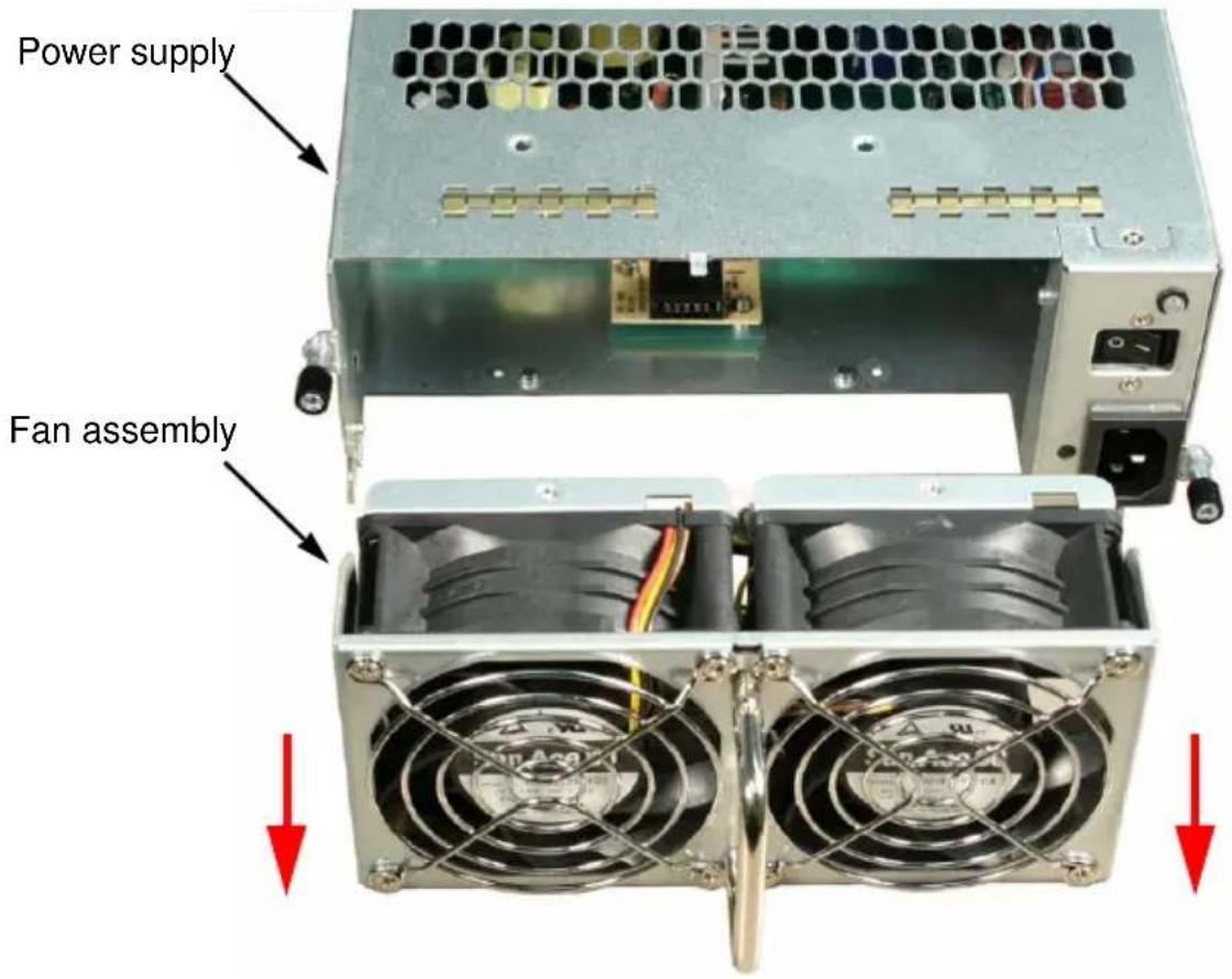
Installing the Fan Assembly
To install the power supply fan assembly:
- Insert the new fan assembly into the power supply.
Be sure the tab passes through the locator hole. See Figure 3.
Figure 3. Tab in locator hole

natural_image
Close-up of a server rack with two fans and a red circle highlighting a component (no readable text or symbols)-
Install the five screws that hold the fan assembly in place. See page 53, Figure 1.
-
Put the power supply back into the VTrak enclosure and tighten the mounting screws.
-
Plug in the power cord and turn on the power supply at the switch.
This completes the replacement procedure for the power supply fan.
Index
Symbols
? command 42
A
AAMUX adapter 15, 17, 28, 43
about this manual 1
B
BTUs/hour 6
C
cable
RJ11-to-DB9 9, 23, 26
SAS SFF-8088 9, 20, 21
CE statement 8
clear link error count 41
clips, power cord 24
code violation count 40
Command ? 42
enclosure 32, 43
factorydefaults 37
help 37
link 38, 43
route 41
uptime 42
Command Line Interface (CLI) 32
Connection
CLI 26
power 24
D
Data cable connections
Basic DAS 19
Cascading DAS 20
Redundant Cascading DAS 21
data rate 39
device type 39
disk drives
hot-swappable 44
install 14
LEDs 25, 28
numbering 14
supported 43
disparity error count 40
drive type 39
E
enclosure
command 32, 43
global status LED 25, 27
information 33
reboot 31
settings 35
shutdown 31
error counts 40
ESD Warning 9, 51, 52
F
factorydefaults command 37
fan, power supply
install 55
remove 53
FCC statement 8
Features and Benefits 5
firmware version, view 33
G
GOST-R statement 8
H
HBA card 19, 20, 21, 28
help command 37
|
I/O module
activity LED 25, 27
add second module 51
role (primary/secondary) 32, 33, 43, 52
status LED 30
invalid D-word count 40
IRAM statement 8
L
LEDs
disk drive 25, 28
drive carrier 28
enclosure global status 25, 27
front panel 24, 27
I/O module 30
I/O module activity 25, 27
power 25, 27
power supply 29
system heartbeat 25, 27
link
clear error count 41
command 38, 43
connection 39
statistics 39
status 38
M
mapping, routing table 41
MIC statement 8
minimum fan speed setting 36
0
operating systems, supported 6
overview of VTrak 2
P
phy
change count 40
number 39, 40
ready status 39
reset problem count 40
port number 39, 40
power
connection 24
consumption 6
LED 25, 27
power cord clips 24
power supply
LED 29
redundancy 44
status 29, 33
power supply fan
install 55
remove 53
R
RAID controller 28
regulatory statements 8
restoring factory default values 37
returning product for repair 49
RJ11-to-DB9 cable 9, 23, 26
route command 41
routing table mapping 41
S
SAS
cable 19
HBA card 19, 20, 21, 28
no routing entry exists 42
SAS address
connectors 34
drives 34
expander 34
routing table 41
Serial cable connections 26
serial number, view 33
setting
enclosure global 27, 28
I/O module 30
phy 39
power supplies 29, 33
temperatures 33
voltage 33
subsystem
reboot 31
shutdown 31
System heartbeat LED 25, 27
system temperatures 33
T
Technical Support, contact 44
temperature settings 35
temperature status 33
thermal management setting 36
thermal output 6
U
uptime command 42
V
view
enclosure settings 35
firmware version 33
I/O module role 33
link status and statistics 38
power supply status 33
routing table mapping 41
SAS addresses 34
serial number 33
system uptime 42
system voltages 33
voltage status 33
VTrak
dimensions 7
drives and ports 6
environmental 7
OS support 6
overview 2
power 6
reboot 31
safety standards 7
shutdown 31
warranty 8, 47
W
warranty, VTrak 47
- Copyright
- Trademarks
- Important data protection information
- Notice
- Recommendations
- Contents
- Chapter 1: Introduction to VTrak .....1
- Chapter 2: Installation .....9
- Chapter 3: Management .....27
- Chapter 3: Management, cont.
- Chapter 4: Support .....43
- Appendix A: Miscellaneous .....51
- Index. 57
- Chapter 1: Introduction to VTrak
- About This Manual
- Note
- Important
- Caution
- Warning
- VTrak Overview
- Architectural Description
- Specifications
- Drives and Ports
- Operating System Support
- Environmental
- Dimensions
- Safety Standards
- Warranty and Support
- CE Statement
- FCC Statement
- GOST-R Statement
- Chapter 2: Installation
- Unpacking the VTrak
- Notices
- Mounting the VTrak in a Rack
- Cautions
- Installing Disk Drives
- Drive Slot Numbering
- Installing 3.5-inch Disk Drives
- Installing 2.5-inch Disk Drives
- Making Data Connections
- Basic DAS Connection
- Cascading DAS Connection
- Redundant Cascading DAS Connection
- Setting Up Serial Cable Connections
- Connecting the Power
- Setting Up the CLI Connection
- Chapter 3: Management
- Front Panel LEDs
- Drive Carrier LEDs
- Power Supply LED
- I/O Module LEDs
- Shutting Down and Restarting the VTrak
- Command Line Interface
- Command Set
- Enclosure Command
- Viewing Enclosure Information
- The system returns:
- Making Enclosure Settings
- Viewing Current Settings
- Setting Temperature Thresholds
- Setting Thermal Management
- Setting Shutdown
- Setting Minimum Fan Speed
- Factorydefaults Command
- Help Command
- Link Command
- Viewing Link Status
- Clearing the Error Count
- Route Command
- Route Troubleshooting
- Uptime Command
- ? Command
- Chapter 4: Support
- Frequently Asked Questions
- Can I hot-swap a failed drive with a new one?
- Can the VTrak run using just one power supply?
- Contacting Technical Support
- Technical Support Services
- United States
- Limited Warranty
- Disclaimer of other warranties
- Your Responsibilities
- Returning the Product For Repair
- Appendix A: Miscellaneous
- Adding a Second I/O Module
- Replacing a Power Supply Fan
- Removing the Fan Assembly
- Installing the Fan Assembly
- Index
- Symbols
- A
- B
- C
- D
- E
- F
- G
- H
- |
- L
- M
- 0
- P
- R
- S
- T
- U
- V
- W
Brand : Promise Technology
Model : VTrak J830SD
Category : Disk array