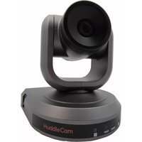
3XW-G2 - Video Conferencing System HuddleCamHD - Free user manual and instructions
Find the device manual for free 3XW-G2 HuddleCamHD in PDF.


| Product Type | Video Conferencing Camera |
| Brand | HuddleCamHD |
| Model | 3XW-G2 |
| Sensor | 1/2.8" CMOS, 3.27 Megapixels |
| Video Resolution | 1920x1080p at 30fps, 1280x720p at 30fps |
| Optical Zoom | 3x (f=3-9mm, F1.2-F2.2) |
| Field of View | 23° (tele) to 90° (wide) |
| Minimum Illumination | 0.25 Lux at F1.2 |
| Pan Range | 0° to 359° |
| Tilt Range | Up 90°, Down 45° |
| Presets | 64 presets, 4 patrol lines |
| Video Interface | USB 3.0 (backward compatible with USB 2.0) |
| Control Interface | Mini DIN-8 (VISCA IN/OUT/RS485) |
| Power Supply | DC 12V, 2A (included adapter) |
| Power Consumption | 24W max |
| Dimensions (W x H x D) | 5.7 x 6.4 x 5.8 in (145 x 163 x 148 mm) (tilt up adds 1.4 in height) |
| Weight | 2.4 lbs (1.1 kg) |
| Material | Aluminum and plastic |
| Color | Gray or White |
| Operating Temperature | 32°F to 113°F (0°C to 45°C) |
| Warranty | 2 years parts and labor |
| Included Accessories | Power adapter, USB 3.0 cable (3m), serial cables, IR remote, mounting bracket, screws, user manual |
Frequently Asked Questions - 3XW-G2 HuddleCamHD
User questions about 3XW-G2 HuddleCamHD
0 question about this device. Answer the ones you know or ask your own.
Ask a new question about this device
Download the instructions for your Video Conferencing System in PDF format for free! Find your manual 3XW-G2 - HuddleCamHD and take your electronic device back in hand. On this page are published all the documents necessary for the use of your device. 3XW-G2 by HuddleCamHD.
USER MANUAL 3XW-G2 HuddleCamHD
natural_image
HuddleCam camera with adjustable lens and base mount (no visible text or symbols on device body)Precautions.
Safety Tips
- Please read this manual carefully before using the camera.
- Avoid damage from stress, violent vibration or liquid intrusion during transportation, storage or installation.
- Take care of the camera during installation to prevent damage to the camera case, ports, lens or PTZ mechanism.
- Do not apply excessive voltage. (Use only the specified voltage.) Otherwise, you may experience electrical shock.
- Keep the camera away from strong electromagnetic sources.
- Do not aim the camera at bright light sources (e.g. bright lights, the sun, etc.) for extended periods of time.
- Do not clean the camera with any active chemicals or corrosive detergents.
- Do not disassemble the camera or any of the camera's components. If problems arise, please contact your authorized dealer.
- After long term operation, moving components can wear down. Contact your authorized dealer for repair.
In The Box
Supplied Equipment
• HD Color Video Camera (1)
• 12V/2.0A DC Power Adapter (1)
• Installation Bracket (1)
• Installation Screw (1)
• USB 3.0 Data Cable (3m), Serial Control Cables (RS-232C to RS-485)
• IR Remote Controller (1)
- User Manual (1)
152 Robbins Rd, Downingtown, PA, 19335, USA - HuddleCamHD.com | 1 800 - 486-5276
Physical Description......
- Front View......
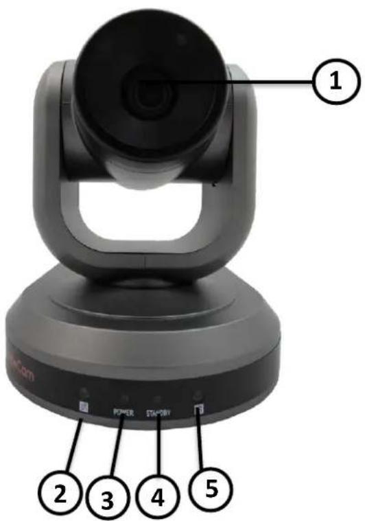
- Lens
- IR Receiver
To receive IR remote controller signal.
- Power LED
Blue LED lights when unit is powered and on.
- Stand by LED
Orange LED lights when unit is powered and in standby.
- IR Receiver
To receive IR remote controller signal.

HuddleCamHD
152 Robbins Rd, Downingtown, PA, 19335, USA - HuddleCamHD.com | 1 800 - 486-5276
- Rear View......
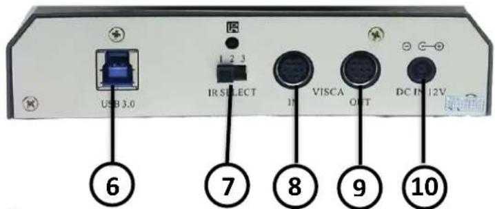
- USB 3.0 Interface
For connection to PC USB 3.0 port (also compatible with USB 2.0 port and driver).
- IR Selective Switch
When using only one remote to control more than one camera, this switch will assign a unique ID to each camera.
- VISCA IN Port
For hard wired remote control from a 3^rd party PC, joystick, etc...
- VISCA Out Port/RS485
Used for daisy chaining multiple cameras for RS-232/RS-485 control.
- DC IN 12V Socket
Only use the Power Adapter supplied with this camera.

HuddleCamHD
152 Robbins Rd, Downingtown, PA, 19335, USA - HuddleCamHD.com | 1 800 - 486-5276
- Bottom View......

- Dip-Switch
Used for selecting baud rate and the remote signal output switch.
- Tripod
Will accept 1/4-20 bolt from 3 ^rd party tripod, wall or ceiling mount.

HuddleCamHD
152 Robbins Rd, Downingtown, PA, 19335, USA - HuddleCamHD.com | 1 800 - 486-5276
- Dip-Switch Settings.....
Note: When changing Dip-Switch settings, make all changes with camera powered off.

Dip-Switch 1 - (To set communication baud rate).
Dip-Switch 2 - (To set control protocol).
Dip-Switch 3 - (Set only for firmware upgrading).
Dip Switch 4 & 5 - (To set camera's RS232/RS485 ID number - for daisy chain wired control).
Camera address code setting
| Dip-switch4 | Dip-switch 5 | |
| 1 | OFF | OFF |
| 1 | OFF | ON |
| 2 | ON | OFF |
| 3 | ON | ON |

HuddleCamHD
152 Robbins Rd, Downingtown, PA, 19335, USA - HuddleCamHD.com | 1 800 - 486-5276
Cable Connection Info.
VISCA RS-232C - IN Reference......

| Pin S/N | Function |
| 1 | DTR IN |
| 2 | DSR IN |
| 3 | TXD IN |
| 4 | GND |
| 5 | RXD IN |
| 6 | GND |
| 7 | IR Commander Signal OUTPUT |
| 8 | NO Connection |
VISCA RS-232C - Out Reference......
VISCA RS-232C OUT

| Pin S/N | Function | |
| RS-232 | RS-485 | |
| 1 | DTR OUT | TX+ |
| 2 | DSR OUT | TX- |
| 3 | TXD OUT | |
| 4 | GND | |
| 5 | RXD OUT | |
| 6 | GND | |
| 7 | RS-485 - | |
| 8 | RS-485 + | |
OSD MENU
On Screen Display Menu - Use the OSD menu to access and change the camera's settings.
Note: You cannot manually move the camera (pan/tilt) when the OSD menu is visible on the screen.
The Dome OSD Menu is as follows:
• Pan Speed Default Value: 20
- Set speed of Pan motor
- Range = 1 - 63
- Tilt Speed Default Value: 20
- Set speed of Pan motor
- Range = 1 - 63
- Scan Speed (Auto Pan Mode) Default Value: 6
- Set speed of boundary scan
- Range = 1 - 63
• Tour Path (uses presets) Default Value: 1
○ Select desired tour path
- Range = 1 - 4
• Tour Dwell Default Value: 5
- Set duration to dwell on each preset
- Range = 1 - 60
- Proportion (Pan + Tilt speed proportional to Zoom level) Default Value: On
- Set Proportion
■ Range = On - Off
• Auto Rev Default Value: P
- Set camera mounting orientation
■ N for inverted ceiling mount, P for std. mount
• Frame Default Value: 60Hz
- Set Refresh Rate

HuddleCamHD
152 Robbins Rd, Downingtown, PA, 19335, USA - HuddleCamHD.com | 1 800 - 486-5276
■ Range = 50Hz or 60 Hz
- Preset Freeze (Provides auto freeze frame when switching presets)
Default Value: Off
■ Range = On - Off
The Lens OSD Menu is as follows:
- BL (BACKLIGHT) Default Value: OFF - ON/OFF
- SATURATION Default Value: 3 - 0-15
- SHARPNESS Default Value: 9 - 0-15
- NR (Noise Reduction) Default Value: Auto - Adjustable Value: Off, AUTO, 1-4
- WB (White Balance) Default Value: Auto - Auto/Manual/Outdoor/Indoor/One Push/ATW
(Manual Settings):
- R GAIN (Red Gain) Default Value: 76 - Adjustable Scope: 0-255
- B GAIN (Blue Gain) Default Value: 82 - Adjustable Scope: 0-255
- AE (Auto Exposure) Default Value: Auto - Auto/Manual/Shutter/Iris/Bright
(Manual Settings):
- SHUTTER Default Value: 1/90 - Shutter Speed Range: 1/60-1/10000
- IRIS Default Value: F8.0 - Close/F1.6-F14
• BRIGHT Default Value: 23

HuddleCamHD
152 Robbins Rd, Downingtown, PA, 19335, USA - HuddleCamHD.com | 1 800 - 486-5276
- Set Brightness 0 - 31
IR Remote Controller
(Note: Some buttons do not operate for all camera models)
1. Reset:
Restarts the camera and restores it to Factory Default settings. (Note: Will delete all memory).
2. Camera Selection
Select Camera ID: 1, 2 or 3
3. Preset Positions
1-9: Preset Positions
Set: Setting Preset Position
Clear: Clear Preset Position
Call: Call Preset Position
Note: If you want to set (or call) the first preset position to 1, you should press number key "1", then press "Set" (or "Call") to set (call) the position.
4. Fast Zoom in/out Control Zone
+: Zoom in quickly
-: Zoom out quickly
5. Pan/Tilt Controller
Move Up
Move Down
Move Left
Move Right
Auto Pan
6. Additional Function Zone
Freeze: Image Freeze
BL: Back-light Compensation
WB: White Balance
AE: Auto Exposure
D Zoom: Digital Zoom
HDMI: Swap to HDMI video output
DVI: Swap to DVI video output
Format: Swap between different formats
7. Power Supply Switch
Switch for turning camera on
(i.e. Stand-By mode vs. Working mode)
8. OSD Menu Zone
Dome OSD: Enter Pan Tilt Zoom OSD menu
Lens OSD: Enter lens OSD menu
9. Slow Zoom In/Out Zone
+: Zoom in slowly
-: Zoom out slowly
10. Focus Control Zone
Auto: Turn on auto focus
Manual: Turn on manual focus
Far: Set focus at farther distance
Near: Set focus at nearer distance

Page 11 of 19

HuddleCamHD
152 Robbins Rd, Downingtown, PA, 19335, USA - HuddleCamHD.com | 1 800 - 486-5276
11. Pan/Tilt Function Zone
L-Limit: Set left boundary limit scanning position
Scan: Enable Boundary Scanning (Auto Panning)
R-Limit: Set right boundary limit scanning position
Home: Go to camera's Home position
Tour: Enable automatic patrol tour of presets
Rev: Enable image flip for ceiling mounting
Connection Instructions
- Connect included Power Supply to the camera.
- Wait for camera to come to Home Position.
- Connect included USB 3.0 cable to camera and USB 3.0 port of PC (unit is also backwards compatible with USB 2.0 port).
- Select and configure camera in your software of choice.
NOTE: Failure to follow this sequence may result in no connection to PC.
Care Of The Unit.
Remove dust or dirt on the surface of the lens with a blower (commercially available).

HuddleCamHD
152 Robbins Rd, Downingtown, PA, 19335, USA - HuddleCamHD.com | 1 800 - 486-5276
Installation Instructions.
Desktop Installation.
When using the HuddleCam™ on a desk, make sure that it will stand level. If you want to use the camera on an incline, make sure the angle is less than 15 degrees to ensure that the camera's pan and tilt mechanism operates normally.

natural_image
Line drawings of two computer monitors with front and back views, showing front and side views (no text or symbols)Max 15°
Tripod Installation.
When using the HuddleCam™ with a tripod, screw the tripod to the bottom of the camera. The tripod screw must fit below specifications:
Note: Tripod must stand on a level surface.

$$ \varrho = 5 - 7 \mathrm{mm} $$

HuddleCamHD
152 Robbins Rd, Downingtown, PA, 19335, USA - HuddleCamHD.com | 1 800 - 486-5276
Ceiling Mount
Step 1:
Ceiling Bracket

natural_image
Pure mechanical component diagram without any text, numbers, or symbolsCeiling
For hard ceilings Use the supplied plastic anchors and screws to fix the ceiling bracket to the ceiling.
For acoustic tile ceilings cut a piece of plywood 12" x 23.75" to use as a tile bridge above the ceiling tile. Use the supplied screws (without plastic anchors) to fix the ceiling bracket to the plywood, sandwiching the ceiling tile in between. Do not over-tighten.
NOTE: The four raised areas of the ceiling bracket must face towards the ceiling.
Step 2:
natural_image
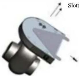
3D mechanical component diagram showing a curved housing with directional arrows and a label 'Slott' (no readable text or symbols beyond the label)Slotted bolts
Use the two slotted bolts to fix the camera bracket to the bottom of the camera body. The 1/4 -20 bolt is for the threaded insert in the camera body. The smaller bolt threads into the bracket and pins the camera in place using the unthreaded opening on the camera body.
Camera Bracket
Step 3:

Slide the camera bracket assembly on to the ceiling bracket, allowing the 2 slotted bolt heads to fit over the large keyhole opening in the ceiling bracket. Slide the camera and camera bracket until both bolt heads are fitted into the narrower slot of the large keyhole opening.
Step 4:

natural_image
3D rendered mechanical component with directional arrows indicating movement or force (no text or symbols)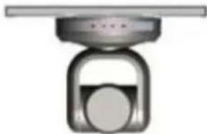
natural_image
Mechanical component with a circular base and central knob, mounted on a flat top (no text or symbols visible)Use the locking screw to lock the ceiling and camera brackets together to finish the installation
Troubleshooting
| Problem | Cause | Resolution |
| There is no power to the camera. | Power adapter is disconnected from mains or from camera. | Check the connections between the camera, power adapter and mains. If anything is disconnected, reconnect it. |
| Power switch is set to OFF. | Set the power switch to ON. | |
| Camera will not connect to the PC via USB. | USB cable is bad. | Try new USB Cable |
| Camera connects sometimes. | Connect USB only after camera has completely booted. | |
| Camera unable to pan, tilt, and/or zoom. | Menu is currently displayed on the screen. | Retry after exiting the menu. |
| Pan, tilt or zoom range limit was reached. | Try to pan/tilt/zoom in the other direction. | |
| Remote control not working. | The “camera select” button on the remote control is not set to match the “IR select” switch number set on the camera. | Choose the correct “IR select” number to match camera settings. |
| Camera cannot be controlled via VISCA. | The connection between the PC and camera is incorrect. | Refer to Cable Connection Info section of this manual. |
| Commands being sent are incorrect. | Refer to VISCA manual. | |
| The Camera is not working at all. | No response or image from camera. | Disconnect power, and wait a few minutes, then connect the power again. Retry. |

HuddleCamHD
152 Robbins Rd, Downingtown, PA, 19335, USA - HuddleCamHD.com | 1 800 - 486-5276
Important Notes Regarding USB Connectivity:
USB 3.0 ports are backwards compatible with USB 2.0 devices. USB 2.0 ports are not completely forward compatible with USB 3.0 devices (some USB 3.0 devices will connect to USB 2.0 with limited functionality).
External USB hubs should be avoided (i.e. give the camera its own USB port on the device) as they are not well suited to transmitting HD video reliably.
USB extension systems must be fully compatible with the version of USB that you are using and must utilize an external power supply, when required. Caution: Some “compatible”
USB 3.0 extenders do not actually have the full 5Gbps bandwidth required for uncompressed HD video - so check bandwidth specs. Always connect the HuddleCam directly to the device in order to associate the UVC drivers before attempting to use any extension system.
USB 3.0 power saving settings in the device's operating system should be turned off completely for reliable USB 3.0 camera connectivity.
HuddleCam Cameras
All HuddleCamHD cameras utilize the UVC (USB Video Class) drivers that are built into Windows, Mac OS and Linux to stream HD video to your device via your device's USB port (USB 2.0 or USB 3.0 depending upon HuddleCam model). When your device successfully recognizes the camera, your device will register the HuddleCam as an “imaging device”. You can see this in your Windows Device Manager program (type “device manager” into the Windows search tool) as shown in the screenshot, below:

HuddleCamHD
152 Robbins Rd, Downingtown, PA, 19335, USA - HuddleCamHD.com | 1 800 - 486-5276

In this example, you can see the HuddleCam model in use connected as a fully functional USB 3.0 device (HuddleCamHD) as well as a USB 2.0 device with limited functionality (USB2.0 Camera).
If your device has not connected to or has not recognized the HuddleCam as an imaging device (in which case, you may see a new “unknown device”, “Westbridge” or “CYTFX3” labeled device show up in Device Manager’s “Universal Serial Bus Controllers” section rather than in the “Imaging Devices” section), the HuddleCam will not be available to programs that utilize a camera. In this case, try restarting the device and reconnecting the camera via USB (USB 2.0 or USB 3.0 depending upon HuddleCam model).

HuddleCamHD
152 Robbins Rd, Downingtown, PA, 19335, USA - HuddleCamHD.com | 1 800 - 486-5276
Similarly, you can see a connected device in System Information on a MAC. See screenshot below:

In this example, you can see the HuddleCam model in use connected as a fully functional USB 3.0 device “HuddleCamHD” as well as a “USB2.0 camera” with limited functionality (USB2.0 camera).
Model Number: HC3XW-xx-G2
Camera & Lens
• Video CMOS Sensor 1/2.8" CMOS 3.27 Mega Pixel
• Frame Rate 30fps 1920 x 1080p, 30fps 1280 x 720p
- Lens Zoom 3X Optical Zoom, f=3-9mm F1.2-F2.2
• Field of View 23° (tele) to 90° (wide)
• Min Lux 0.25 Lux at F1.2
- Warranty 2 years parts and labor
Pan/Tilt Movement
• Pan Movement 0-359°
- Tilt Rotation Up: 90^ , Down: 45^
• Presets 64 Presets, 4 Patrol lines
Rear Board Connectors
• Video Interface USB 3.0
• Control Signal Interface Mini DIN-8 (VISCA IN, VISCA OUT/RS485)
• Control Signal Config. Dip-Switch Pin 6/TTL Signal
• Baud Rate 9600 bps
• Power Supply Interface DC 12V 2A
Electrical Index
• Power Supply Adapter 12V DC 2A
• Input Voltage 12V DC (10.5-14V DC)
• Input Power 24W (Max)
• Working Environment Indoor
Physical
• Material Aluminum, Plastic
- Dimensions 5.7"W x 6.4"H x 5.8"D [7.2"H w/ Tilt Up]
(145mm x 163mm x 148mm [183mmH w/ Tilt Up])
• Weight 2.4 lbs (1.1 kg)
- Box Dimensions 12.13" x 9.25" x 9.5" (309mm x 235mm x 242mm)
- Boxed Weight 5.6 lbs (2.55 kg)
• Color Gray or White
- Operating Temperature 32^ to +113^ (0°C to +45°C)
• Storage Temperature -14°F to 140°F (-10°C +60°C)
• Working Environment Indoor only


- Precautions.
- Safety Tips
- In The Box
- Supplied Equipment
- HuddleCamHD
- Cable Connection Info.
- OSD MENU
- The Dome OSD Menu is as follows:
- Robbins Rd, Downingtown, PA, 19335, USA - HuddleCamHD.com | 1 800 - 486-5276
- The Lens OSD Menu is as follows:
- (Manual Settings):
- IR Remote Controller
- Reset:
- Camera Selection
- Preset Positions
- Fast Zoom in/out Control Zone
- Pan/Tilt Controller
- Additional Function Zone
- Power Supply Switch
- OSD Menu Zone
- Slow Zoom In/Out Zone
- Focus Control Zone
- Pan/Tilt Function Zone
- Connection Instructions
- Care Of The Unit.
- Installation Instructions.
- Desktop Installation.
- Tripod Installation.
- Ceiling Mount
- Troubleshooting
- Important Notes Regarding USB Connectivity:
- HuddleCam Cameras
- Camera & Lens
- Pan/Tilt Movement
- Rear Board Connectors
- Electrical Index
- Physical
Brand : HuddleCamHD
Model : 3XW-G2
Category : Video Conferencing System