
CNXRY-8 - Switch Crestron - Free user manual and instructions
Find the device manual for free CNXRY-8 Crestron in PDF.


| Product Type | Relay Output Expansion Card |
| Brand | Crestron |
| Model | CNXRY-8 |
| Number of Relays | 8 |
| Relay Type | Normally open, isolated |
| Maximum Contact Rating | 1A, 30 VAC/VDC |
| Arc Suppression | MOV (metal oxide varistor) across contacts |
| Power Requirements | 24 VDC, network power, 3 Watts |
| Compatible Control Systems | Crestron CNX Generation Control System (e.g., CNMSX, CNMSX-PRO) |
| Software Requirements | SIMPL Windows v1.19.08 or later; CNX OS v5.01.00 or later; CNX Monitor v2.00 or later |
| Dimensions (Height) | 0.98 in (2.49 cm) |
| Dimensions (Width) | 5.00 in (12.70 cm) |
| Weight | Approximately 0.25 lb (0.11 kg) |
| Mounting | Slides into unoccupied slot in control system; secured with thumb-nail screws |
| Connector | Male 16-pin connector on faceplate; includes mating 16-position plug |
| ESD Protection | Electrostatic sensitive device; handle with precautions |
| Programming | Via SIMPL Windows; uses Interlock symbols for mutually exclusive relay activation |
| Warranty | 3 years from date of purchase (CRESTRON Limited Warranty) |
| Certifications | CE marked |
Frequently Asked Questions - CNXRY-8 Crestron
User questions about CNXRY-8 Crestron
0 question about this device. Answer the ones you know or ask your own.
Ask a new question about this device
Download the instructions for your Switch in PDF format for free! Find your manual CNXRY-8 - Crestron and take your electronic device back in hand. On this page are published all the documents necessary for the use of your device. CNXRY-8 by Crestron.
USER MANUAL CNXRY-8 Crestron
CNX Relay Output Expansion Card
Operations Guide
Contents
CNX Relay Output Expansion Card: CNXRY-8 1
Description....1
Functional Description .... 1
Physical Description....1
Leading Specifications....2
Setup 2
Installation....2
Preparation for Use....3
Programming with SIMPL Windows 3
How the Program Works....3
How to Create the Program....4
Problem Solving 7
Troubleshooting 7
Further Inquiries....7
Future Updates 7
Return and Warranty Policies....8
Merchandise Returns / Repair Service 8
CRESTRON Limited Warranty 8
CNX Relay Output Expansion Card: CNXRY-8
Description
Functional Description
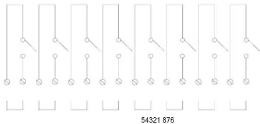
The CNXRY-8 Relay Output Expansion Card provides 8 isolated, normally open relay closures. The maximum rating per contact measures 1A, 30 VAC/VDC. There are MOV (metal oxide varistor) arc suppression devices across the contacts for use with “real world” loads. Refer to the schematic below.
CNXRY-8 Schematic
Physical Description
The CNXRY-8, shown below, is a circuit board fastened to an aluminum faceplate. The card is manufactured to easily fit into an unoccupied slot in a Crestron ^® CNX Generation Control System.
CNXRY-8 Faceplate

The faceplate contains one male, 16-pin connector. Each relay is isolated from the others. Silk screening is applied to the faceplate; relay pin pairs are labeled 1 through 8. A supplied 16-position connector can be wired and attached to the card.
Leading Specifications
The table below provides a summary of leading specifications for the CNXRY-8. Dimensions and weight are approximations rounded to the nearest hundredth unit.
Leading Specifications of the CNXRY-8
| SPECIFICATION DETAILS | |
| Power Requirements | 24 VDC, network power; 3 Watts |
| Maximum Rating per Contact | 1A, 30 VAC/VDC |
| SIMPL Windows | Version 1.19.08 or later |
| CNX Operating System | Version 5.01.00 or later |
| CNX Monitor | Version 2.00 or later |
| Dimensions | Height: 0.98 in (2.49 cm)Width: 5.00 in (12.70 cm) |
As of the date of manufacture, the unit has been tested and found to comply with specifications for CE marking.

Setup
Installation
Items required to install the CNXRY-8 are already attached to the unit. The only tools required are a Phillips tip screwdriver and a grounding strap. Follow the assembly procedure below.
CAUTION: The CNXRY-8 contains electrostatic sensitive devices (ESD); observe precautions for handling ESDs to avoid damaging the card.
NOTE: If installing the CNXRY-8 into a CNMSX-AV, it is assumed that the CNXCAGE has been installed.
- Disconnect power from the CNMSX.
- Use the Phillips tip screwdriver and remove two screws and blank faceplate from the control system.
- Align the CNXRY-8 with the card guides in the open slot and slide the expansion card into position.
- Firmly press both ends of the CNXRY-8 faceplate to seat the expansion card into the control system connector.
- Tighten the thumb-nail screws to secure the CNXRY-8 to the control system.
- Reapply power to the CNMSX.
Preparation for Use
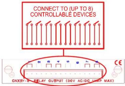
Connections are made to the eight normally open, isolated relays of the CNXRY-8. The connector is labeled 1 through 8. Refer to a sample hookup diagram below and aside from reapplying power to the control system last, complete the connections in any order.
Sample Hookup Connections for CNXRY-8
Programming with SIMPL Windows
SIMPL (Symbol Intensive Master Programming Language) is an easy-to-use programming language that is completely integrated and compatible with all Crestron system hardware. The objects that are used in SIMPL are called symbols. SIMPL Windows offers drag and drop functionality in a familiar Windows ^® environment.
SIMPL Windows is Crestron Electronics' software for programming Crestron control systems. It provides a well-designed graphical environment with a number of workspaces (i.e., windows) in which a programmer can select, configure, program, test, and monitor a Crestron control system.
The next two subsections describe a sample SIMPL Windows program that utilizes the CNXRY-8. The first subsection details how the sample program works with a textual description and block diagram. The second subsection provides a broad description of how to actually create the SIMPL Windows program.
NOTE: The following description assumes that the reader has knowledge of SIMPL Windows. If not, please refer to the extensive help information provided with the software.
How the Program Works
A basic CNXRY-8 SIMPL program is shown on the next page in block diagram form. For this example, the CNXRY-8 occupies slot 1 of a CNMSX-PRO. Assume there are two rooms that have lighting systems that are controlled via relays. Each room can have up to four scenes of lighting. A scene is engaged by latching a relay. Only one scene can be activated in a room at a time.
Room 1 uses relays A1 through A4; room 2 uses relays A5 through A8. When the user presses any of the buttons for room 1 (join numbers 1-4), the corresponding signal goes high on the input of the Interlock symbol for room 1. The corresponding output of the Interlock latches high. Since the Interlock is mutually exclusive, only
that output is high. The corresponding relay then latches high on the CNXRY-8 card.
Block Diagram of CNXRY-8

flowchart
graph TD
    subgraph Module A
        A1["Room-1-Scene-1-f"] --> A1a["1b1 press1"]
        A2["Room-1-Scene-2-f"] --> A2a["1b2 press2"]
        A3["Room-1-Scene-3-f"] --> A3a["1b3 press3"]
        A4["Room-1-Scene-4-f"] --> A4a["1b4 press4"]
    end

    subgraph Module B
        B1["Room-2-Scene-1-f"] --> B1a["1b5 press5"]
        B2["Room-2-Scene-2-f"] --> B2a["1b6 press6"]
        B3["Room-2-Scene-3-f"] --> B3a["1b7 press7"]
        B4["Room-2-Scene-4-f"] --> B4a["1b8 press8"]
    end

    A1 --> B1a
    A1 --> B2a
    A2 --> B2a
    A3 --> B3a
    A4 --> B4a
    B1a --> C1["Room-1-Scene-1"]
    B2a --> C2["Room-1-Scene-2"]
    B3a --> C3["Room-1-Scene-3"]
    B4a --> C4["Room-1-Scene-4"]
    C1 --> D1["i1 o1"]
    C2 --> D2["i2 o2"]
    C3 --> D3["i3 o3"]
    C4 --> D4["i4 o4"]

    B1a --> D1
    B2a --> D2
    B3a --> D3
    B4a --> D4

    C1 --> E1["Room-1-Scene-1-f"]
    C2 --> E2["Room-1-Scene-2-f"]
    C3 --> E3["Room-1-Scene-3-f"]
    C4 --> E4["Room-1-Scene-4-f"]
    E1 --> F1["A1"]
    E2 --> F2["A2"]
    E3 --> F3["A3"]
    E4 --> F4["A4"]

    B1a --> G1["Room-2-Scene-1-f"]
    B2a --> G2["Room-2-Scene-2-f"]
    B3a --> G3["Room-2-Scene-3-f"]
    B4a --> G4["Room-2-Scene-4-f"]
    G1 --> H1["A5"]
    G2 --> H2["A6"]
    G3 --> H3["A7"]
    G4 --> H4["A8"]

    B1a --> I1["Room-2-Scene-1-f"]
    B2a --> I2["Room-2-Scene-2-f"]
    B3a --> I3["Room-2-Scene-3-f"]
    B4a --> I4["Room-2-Scene-4-f"]
    I1 --> J1["A5"]
    I2 --> J2["A6"]
    I3 --> J3["A7"]
    I4 --> J4["A8"]

    style Module A fill:#f9f,stroke:#333
    style Module B fill:#f9f,stroke:#333
How to Create the Program
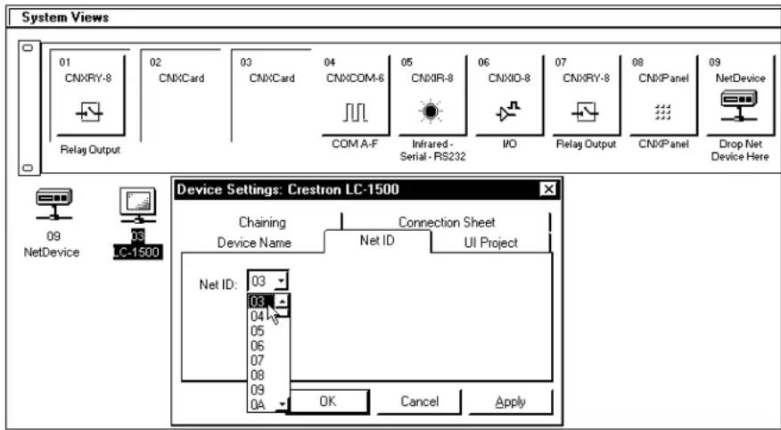
Use the Configuration Manager workspace in SIMPL Windows to select and configure all the devices that need to be included into the system. For this example, add a CNXRY-8 to slot #1 of the CNMSX-PRO. Also add a LC-1500 to the system; its NET ID must be set to 03, shown below.
NOTE: SIMPL Windows v1.19.08 or later is required to program the CNMSX-PRO. If using an earlier version of SIMPL Windows, Crestron recommends a SIMPL Windows and operating system upgrade.
Graphical System View of CNXRY-8 and LC-1500 in SIMPL Windows' Configuration Manager
Use the Programming Manager workspace in SIMPL Windows to select symbols and assign their respective signals. For this example, a touchpanel and CNXRY-8 symbols were added automatically when the devices were added to the system in the Configuration Manager workspace. Expand the Network Modules folder and double click on the touchpanel for a detail view (alternatively CTRL+D or drag and drop into Detail View). Assign signals as shown below.
Graphical Detail View of Touchpanel in SIMPL Windows' Programming Manager
For a more descriptive symbol name, as shown in this illustration, right mouse click on the touchpanel icon in the Network Modules folder in Program View and Select Edit Symbol Comment (alternatively, highlight the icon and depress Ctrl+R or Tab). Enter a new descriptive name in the “Enter Symbol Comment” dialog box and click OK.

flowchart
graph TD
    A["Room-1-Scene-1-f"] --> B["fb1"]
    C["Room-1-Scene-2-f"] --> D["fb2"]
    E["Room-1-Scene-3-f"] --> F["fb3"]
    G["Room-1-Scene-4-f"] --> H["fb4"]
    I["Room-2-Scene-1-f"] --> J["fb5"]
    K["Room-2-Scene-2-f"] --> L["fb6"]
    M["Room-2-Scene-3-f"] --> N["fb7"]
    O["Room-2-Scene-4-f"] --> P["fb8"]
    B --> Q["press1"]
    D --> R["press2"]
    F --> S["press3"]
    H --> T["press4"]
    J --> U["press5"]
    L --> V["press6"]
    N --> W["press7"]
    P --> X["press8"]
    Q --> Y["Room-1-Scene-1"]
    R --> Z["Room-1-Scene-2"]
    S --> AA["Room-1-Scene-3"]
    T --> AB["Room-1-Scene-4"]
    U --> AC["Room-2-Scene-1"]
    V --> AD["Room-2-Scene-2"]
    W --> AE["Room-2-Scene-3"]
    X --> AF["Room-2-Scene-4"]
Expand the Central Control Modules folder and double click on the CNXRY-8 for a detail view (alternatively CTRL+D or drag and drop into Detail View). Assign signals as shown below.
Graphical Detail View of CNXRY-8 in SIMPL Windows' Programming Manager

flowchart
graph TD
    A["Room-1-Scene-1-f"] --> B["A1"]
    C["Room-1-Scene-2-f"] --> D["A2"]
    E["Room-1-Scene-3-f"] --> F["A3"]
    G["Room-1-Scene-4-f"] --> H["A4"]
    I["Room-2-Scene-1-f"] --> J["A5"]
    K["Room-2-Scene-2-f"] --> L["A6"]
    M["Room-2-Scene-3-f"] --> N["A7"]
    O["Room-2-Scene-4-f"] --> P["A8"]
    Q["Built-in 8 Low ..."] --> R
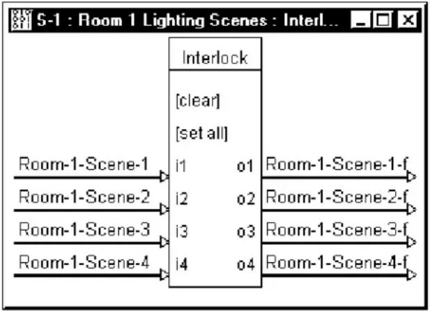
Expand the Logic folder and double click on both Interlock icons for a detail view (alternatively CTRL+D or drag and drop into Detail View). Assign signals as shown after this paragraph.
Graphical Detail View of an Interlock (S-1) in SIMPL Windows' Programming Manager
For a more descriptive symbol name, as shown in these illustrations, right mouse click on the Interlock icon in the Logic folder in Program View and select Edit Symbol Comment (alternatively, highlight the icon and depress Ctrl+R or Tab). Enter a new descriptive name in the “Enter Symbol Comment” dialog box and click OK.
flowchart
graph TD
    A["Room-1-Scene-1"] --> B["i1"]
    C["Room-1-Scene-2"] --> D["i2"]
    E["Room-1-Scene-3"] --> F["i3"]
    G["Room-1-Scene-4"] --> H["i4"]
    B --> I["Interlock"]
    D --> I
    F --> I
    H --> I
    I --> J["Room-1-Scene-1-f"]
    I --> K["Room-1-Scene-2-f"]
    I --> L["Room-1-Scene-3-f"]
    I --> M["Room-1-Scene-4-f"]
Graphical Detail View of an Interlock (S-2) in SIMPL Windows' Programming Manager
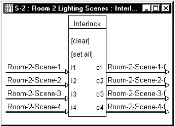
flowchart
graph TD
    A["Room-2-Scene-1"] --> B["i1"]
    C["Room-2-Scene-2"] --> D["i2"]
    E["Room-2-Scene-3"] --> F["i3"]
    G["Room-2-Scene-4"] --> H["i4"]
    B --> I["Interlock"]
    D --> I
    F --> I
    H --> I
    I --> J["Room-2-Scene-1-f"]
    I --> K["Room-2-Scene-2-f"]
    I --> L["Room-2-Scene-3-f"]
    I --> M["Room-2-Scene-4-f"]
Problem Solving
Troubleshooting
The table below provides corrective action for possible trouble situations. If further assistance is required, please contact a Crestron customer service representative.
CNXRY-8 Toubleshooting
| TROUBLE | POSSIBLE CAUSE(S) | CORRECTIVE ACTION |
| CNXRY-8 does not function. | CNX Control System is not receiving power. | Verify power to CNX Control System. |
| Circuit card is not properly seated in slot. | Verify CNXRY-8 is properly inserted into CNX Control System slot per procedures in this Operations Guide. | |
| Programming error. Check SIMPL Windows program. | ||
Further Inquiries
If you cannot locate specific information or have questions after reviewing this guide, please take advantage of Crestron's award winning customer service team by calling the Crestron corporate headquarters at 1-888-CRESTRON [1-888-273-7876]. For assistance in your local time zone, refer to the Crestron website (http://www.crestron.com) for listing of Crestron worldwide offices.
You can also log onto the online help section of the Crestron website to ask questions about Crestron products. First-time users will need to establish a user account to fully benefit from all available features.
Future Updates
As Crestron improves functions, adds new features, and extends the capabilities of the CNXRY-8, additional information and programming examples may be made available as manual updates. These updates are solely electronic and serve as intermediary supplements prior to the release of a complete technical documentation revision.
Check the Crestron website periodically for manual update availability and its relevance. Updates are identified as an “Addendum” in the Download column.
Return and Warranty Policies
Merchandise Returns / Repair Service
- No merchandise may be returned for credit, exchange, or service without prior authorization from CRESTRON. To obtain warranty service for CRESTRON products, contact the factory and request an RMA (Return Merchandise Authorization) number. Enclose a note specifying the nature of the problem, name and phone number of contact person, RMA number, and return address.
- Products may be returned for credit, exchange, or service with a CRESTRON Return Merchandise Authorization (RMA) number. Authorized returns must be shipped freight prepaid to CRESTRON, 6 Volvo Drive, Rockleigh, N.J., or its authorized subsidiaries, with RMA number clearly marked on the outside of all cartons. Shipments arriving freight collect or without an RMA number shall be subject to refusal. CRESTRON reserves the right in its sole and absolute discretion to charge a 15% restocking fee, plus shipping costs, on any products returned with an RMA.
- Return freight charges following repair of items under warranty shall be paid by CRESTRON, shipping by standard ground carrier. In the event repairs are found to be non-warranty, return freight costs shall be paid by the purchaser.
CRESTRON Limited Warranty
CRESTRON ELECTRONICS, Inc. warrants its products to be free from manufacturing defects in materials and workmanship under normal use for a period of three (3) years from the date of purchase from CRESTRON, with the following exceptions: disk drives and any other moving or rotating mechanical parts, pan/tilt heads and power supplies are covered for a period of one (1) year; touchscreen display and overlay components are covered for 90 days; batteries and incandescent lamps are not covered.
This warranty extends to products purchased directly from CRESTRON or an authorized CRESTRON dealer. Purchasers should inquire of the dealer regarding the nature and extent of the dealer's warranty, if any.
CRESTRON shall not be liable to honor the terms of this warranty if the product has been used in any application other than that for which it was intended, or if it has been subjected to misuse, accidental damage, modification, or improper installation procedures. Furthermore, this warranty does not cover any product that has had the serial number altered, defaced, or removed.
This warranty shall be the sole and exclusive remedy to the original purchaser. In no event shall CRESTRON be liable for incidental or consequential damages of any kind (property or economic damages inclusive) arising from the sale or use of this equipment. CRESTRON is not liable for any claim made by a third party or made by the purchaser for a third party.
CRESTRON shall, at its option, repair or replace any product found defective, without charge for parts or labor. Repaired or replaced equipment and parts supplied under this warranty shall be covered only by the unexpired portion of the warranty.
Except as expressly set forth in this warranty, CRESTRON makes no other warranties, expressed or implied, nor authorizes any other party to offer any warranty, including any implied warranties of merchantability or fitness for a particular purpose. Any implied warranties that may be imposed by law are limited to the terms of this limited warranty. This warranty statement suprecedes all previous warranties.
Trademark Information
All brand names, product names, and trademarks are the sole property of their respective owners. Windows is a registered trademark of Microsoft Corporation. Windows95/98/Me/XP and WindowsNT/2000 are trademarks of Microsoft Corporation
This page intentionally left blank.

CRESTRON®
Crestron Electronics, Inc. Operations Guide - DOC. 8121
15 Volvo Drive Rockleigh, NJ 07647 09.98
Tel: 888.CRESTRON
Fax: 201.767.7576 Specifications subject to
www.crestron.com change without notice.


- CNX Relay Output Expansion Card
- Operations Guide
- Contents
- CNX Relay Output Expansion Card: CNXRY-8 1
- CNX Relay Output Expansion Card: CNXRY-8
- Description
- Functional Description
- Physical Description
- Leading Specifications
- Setup
- Installation
- Preparation for Use
- Programming with SIMPL Windows
- How the Program Works
- How to Create the Program
- Problem Solving
- Troubleshooting
- Further Inquiries
- Future Updates
- Return and Warranty Policies
- Merchandise Returns / Repair Service
- CRESTRON Limited Warranty
- Trademark Information
- CRESTRON®
Brand : Crestron
Model : CNXRY-8
Category : Switch