
DSP320.2 - Loudspeaker MERIDIAN - Free user manual and instructions
Find the device manual for free DSP320.2 MERIDIAN in PDF.


| Product Type | In-wall DSP loudspeaker |
| Brand | Meridian |
| Model | DSP320.2 |
| Dimensions (H x W x D) | 290 mm x 290 mm x 103 mm (11.4 in x 11.4 in x 4.0 in) |
| Weight | 5 kg (11 lb) |
| Power Supply | 100-240 V AC, 50/60 Hz, 500 W max |
| Amplifier Power | 2 x 80 W Class D (one per driver) |
| Drivers | 85 mm wide-range (neodymium magnet); 100 mm x 150 mm racetrack oval bass (polypropylene cone) |
| Frequency Response | 50 Hz – 20 kHz (typical) |
| Maximum SPL | 106 dB at 1 m |
| Audio Inputs | 1 x Meridian SpeakerLink (RJ45) |
| Audio Outputs | 1 x Meridian SpeakerLink (RJ45) for daisy-chain |
| Control Options | Meridian controller, IR remote (optional), RS232 via SpeakerLink |
| Channel Modes | Left, Right, L+R, Centre |
| On-board DSP | Thermal and dynamic bass protection, Enhanced Bass Alignment (EBA), FIFO buffering, apodising filters |
| Enclosure | All-metal, self-contained, designed for in-wall installation with optional RF300 rough-in box |
| Grille | Paintable perforated steel, magnetically attached |
| Cleaning Instructions | Clean only with a dry cloth |
| Safety | Do not expose to rain or moisture; no user-serviceable parts; refer servicing to qualified personnel |
| Manufacturer | Meridian Audio Ltd, UK |
Frequently Asked Questions - DSP320.2 MERIDIAN
User questions about DSP320.2 MERIDIAN
0 question about this device. Answer the ones you know or ask your own.
Ask a new question about this device
Download the instructions for your Loudspeaker in PDF format for free! Find your manual DSP320.2 - MERIDIAN and take your electronic device back in hand. On this page are published all the documents necessary for the use of your device. DSP320.2 by MERIDIAN.
USER MANUAL DSP320.2 MERIDIAN
DSP320.2 DSP LOUDSPEAKER
USER GUIDE

ii DSP320.2 DSP Loudspeaker User Guide
Important safety instructions
- Read the instructions.
- Keep these instructions.
- Follow all instructions.
- Do not use this apparatus near water.
- Clean only with a dry cloth.
• Install only in accordance with the manufacturer's instructions.
• Refer all servicing to approved service personnel.
WARNING: TO REDUCE THE RISK OF FIRE OR ELECTRIC SHOCK, DO NOT EXPOSE THIS APPARATUS TO RAIN OR MOISTURE.
This apparatus has been designed with Class 1 construction and must be connected to a mains socket outlet with a protective earthing connection (the third grounding pin).
This apparatus uses a single-pole power switch. As a result it is not isolated from AC mains power when switched off at the rear panel. The apparatus may be isolated from mains power either by unplugging the power connector from the rear of the unit, or by unplugging the connector at the opposing end of the power cord or cable from its supply outlet. As a result, either or both of these connectors should remain accessible.
Safety warnings

WARNING! RISK OF ELECTRIC SHOCK – DO NOT OPEN ATTENTION!

NE PAS OUVRIR - RISQUE DE DÉCHARGE ÉLECTRIQUE
Caution: to reduce the risk of electric shock, do not remove cover. No user serviceable parts inside. Refer servicing to qualified service personnel.

The lightning flash with arrowhead symbol, within an equilateral triangle, is intended to alert the user to the presence of uninsulated “dangerous voltage” within the product’s enclosure that may be of sufficient magnitude to constitute a risk of electric shock to persons.

The exclamation point within an equilateral triangle is intended to alert the user to the presence of important operating and maintenance (servicing) instructions in the literature accompanying the appliance.
Climate
The equipment has been designed for use in moderate climates and in domestic situations.

Only use at an altitude not exceeding 2000m.
Safety warnings
- Do not expose the unit to dripping or splashing.
- Do not place any object filled with liquid, such as a vase, on the unit.
- Do not place naked flame sources, such as lighted candles, on the unit.
To avoid overheating
- Do not position the product in direct sunlight.
- Do not position the product near heat sources, such as a radiator.
- Do not position the product on a soft surface such as a carpet.
- Leave at least 10cm around the product to ensure sufficient ventilation.
To avoid interference
- Do not position the unit near strong electrical or magnetic radiation, such as near a power amplifier.
Radio interference
FCC Warning: This equipment generates and can radiate radio frequency energy and if not installed and used correctly in accordance with our instructions may cause interference to radio communications or radio and television reception. It has been type-tested and complies with the limits set out in Subpart J, Part 15 of FCC rules for a Class B computing device. These limits are intended to provide reasonable protection against such interference in home installations.

EEC: This product has been designed and type-tested to comply with the limits set out in EN55032:2015 and EN55024:2010 + A1:2015.
iv DSP320.2 DSP Loudspeaker User Guide
Copyright and acknowledgements
Sales and service in the UK
Meridian Audio Ltd, Latham Road, Huntingdon, Cambridgeshire, PE29 6YE, England.
Tel (01480) 445678
Email info@meridian.co.uk
Designed and manufactured in the UK
Meridian Audio Ltd, Latham Road, Huntingdon, Cambridgeshire, PE29 6YE, England.
Meridian Audio reserves the right to make changes and improvements to any of the products described in this document without prior notice.
Copyright © 2020 Meridian Audio Ltd.
Part no: P88470/3
Visit us on the Web
www.meridian-audio.com
Product registration
Register your DSP320.2 DSP Loudpeaker at:
www.meridian-audio.com/register

DSP320.2 DSP Loudspeaker User Guide
Contents
Introduction 1
Specifications 3
Installing the DSP320.2 DSP Loudspeaker 4
Front and back panel 7
Setting up the DSP320.2 DSP loudspeaker 9
Applications 1 0
RS232 commands 18
Index 2 5
Introduction
The DSP320.2 is perfect for delivering high-quality music discreetly in any living or cinema room, whether used in stereo systems, full surround sound set-ups, single-loudspeaker installations, or multi-speaker listening zones.
It features one "racetrack" oval bass driver and one 85mm wide-range driver for full-frequency response, each driven by an 80W power amplifier, making it capable of delivering full-range sound at in excess of 106dB at one metre, with bass extension down to 50Hz.
Acoustics
The DSP320.2 has been designed for maximum dispersion and wide listening area plus minimum unwanted diffraction.
Each drive unit is powered individually by a dedicated low-distortion 80W Class-D amplifier.
L+R mode allows a single loudspeaker to be used on its own while still reproducing all the audio present in a stereo recording. In addition, L+R mode makes multiple DSP320.2s a great choice for larger areas with no specific listening position.
On-board DSP
On-board DSP provides thermal and dynamic bass protection while retaining very accurate transients, ensuring that when the loudspeaker is played at high levels – even over prolonged periods of time – it always delivers a clean, detailed and accurate sound.
Enhanced Bass Alignment (EBA)
Meridian's innovative Enhanced Bass Alignment (EBA) uses two different technologies to time-align high, mid, and upper bass frequencies with the low bass, resulting in audibly improved bass transients and added life and clarity.
Enhancement technologies
Meridian's unique suite of proprietary technologies includes FIFO buffering, DSP upsampling, apodising filters, and MHR (Meridian High Resolution) to get the very best performance from all digital sources.
Construction
The DSP320.2 is designed to have an elegant profile, with only 100mm installation depth.
It is constructed from a self-contained, all-metal enclosure. A purpose-built rough-in wall-box is available separately. The rough-in box is first fitted to the wall, and the loudspeaker enclosure is then bolted to the rough-in box. The loudspeaker is supplied with a trim frame which can optionally be fitted
2 DSP320.2 DSP Loudspeaker User Guide
according to the preferred finished appearance. The rough-in box can be adjusted for various wall materials and depths.
The rough-in box is wired to mains power and the loudspeaker carries a captive IEC mains lead which plugs into the mains outlet socket on the rough-in box.
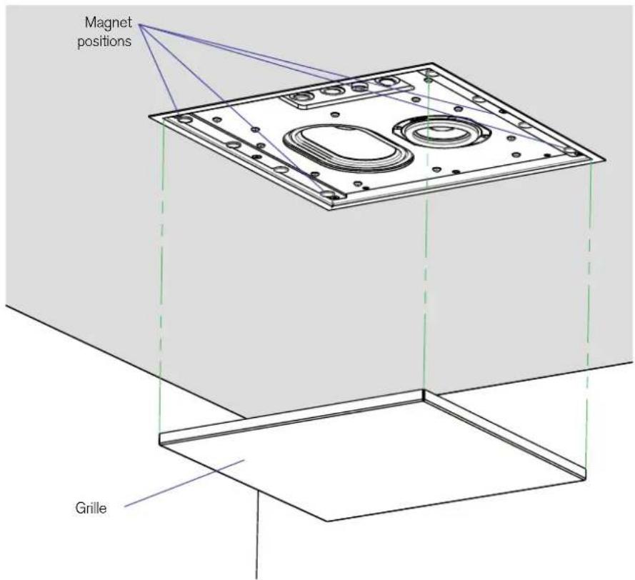
The paintable, perforated steel grille supplied with the loudspeaker can be fitted where required. The grille is held in place by powerful rubber-coated magnets which are attached to the aluminium extrusion that forms the front panel of the loudspeaker enclosure.
Controlling the loudspeaker
The loudspeaker can be controlled in three ways:
- In most installations, the loudspeaker will be controlled by another Meridian product within the system.
- Alternatively, the loudspeaker features an infra-red receiver which allows it to be controlled using a Meridian System Remote.
- Thirdly, the loudspeaker can be controlled using RS232 commands.
Specifications
Audio input
• 1 x Meridian SpeakerLink connector (RJ45).
Audio output
• 1 x Meridian SpeakerLink connector (RJ45).
Drivers
- Wide-range: 85mm with neodymium magnet.
- Bass: 100mm x 150mm racetrack oval with polypropylene cone.
Amplifiers
- Wide-range driver: 1 x 80W Class D amplifier.
- Bass driver: 1 x 80W Class D amplifier.
Performance
- Peak SPL: 106dB @ 1m.
• Bass extension: 50Hz.
Front panel
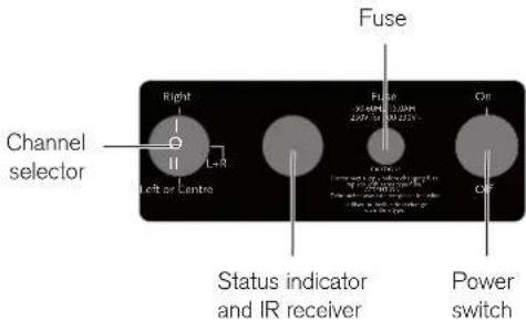
- Switch selects Right, L+R, or Left or Centre.
- IR window.
• LED indicators show power status and configuration settings.
Physical
- Dimensions*: 290mm x 290mm x 103mm (11.4" x 11.4" x 4.0") (H x W x D).
• Weight: 5kg (11lb). - Grille dimensions: 292mm x 292mm x 4mm (11.4" x 11.4" x 0.16") (H x W x D).
- Frame dimensions: 316mm x 316mm x 15mm (12.4" x 12.4" x 0.6") (H x W x D).
* Excluding frame and cable feed channel.
Power
- Flying IEC mains lead connects to mains socket on rough-in wall box.
- 500W max. 100-240V AC, 50/60 Hz.
Protection
- The DSP320 has extensive protection features which are designed to protect the speaker when it is subjected to unusual external events such as surges in the mains electricity.
- In the event this protection is triggered the speaker may require a power cycle to restore normal operation.
4 DSP320.2 DSP Loudspeaker User Guide
Installing the DSP320.2 DSP Loudspeaker
The loudspeaker is designed to be fitted in a Meridian wall box type RF300. If necessary, refer to the RF300 Wall Box Installation Instructions:
https://www.meridian-audio.com/rf300-installation.pdf
Contents
Each DSP320.2 loudspeaker is supplied with the following components:
- Trim-frame.
- Grille.
- 3mm Allen key.
- 4 x M5 guide screws for installing into rough-in box.
- 2 x grille extractor keys.
1. Prepare the loudspeaker for installation
- Remove the grille and scrim from the loudspeaker and put them to one side for use later if required.
- Remove the two plastic nuts and bolts used to retain the trim-frame during shipping.
- Remove the trim-frame.
The loudspeaker can be installed either with or without the trim-frame according to the preferred final appearance.
Because of the weight of the loudspeaker and the method of installation we recommend getting assistance from a second person when installing the loudspeaker.
2. Identify the cables
If the speaker is part of a daisy-chain there will be two SpeakerLink cables in the rough-in box. They must be connected correctly or the system will not function.
- Identify which cable is the SpeakerLink input cable and which is the SpeakerLink output cable.
If there is only one SpeakerLink cable in the rough-in box it will be a SpeakerLink input cable.
- Identify the mains cable from the loudspeaker to the rough-in box.
3. Install the loudspeaker
- If the trim-frame is to be fitted, position it on the back of the loudspeaker.
- Set the power switch on the front of the loudspeaker to the Off position.
- Hold the loudspeaker close to the rough-in box.
- Plug the SpeakerLink input cable into the SpeakerLink input socket on the loudspeaker. If there is also a SpeakerLink output cable plug it into the SpeakerLink output socket on the loudspeaker.
- Plug the loudspeaker's mains cable into the mains inlet socket in the rough-in box.
- Insert the loudspeaker into the rough-in box, taking care not to trap the connecting cables in any way.
• Fix the loudspeaker in place with the four M5 x guide screws.
No additional fixings are required to retain the trim-frame (if fitted).

4. Set the front-panel switches
- Set the channel selection switch according to how the loudspeaker is being used within the system.
Once the associated equipment connected to the loudspeaker is powered up:
- Set the power switch on the front of the loudspeaker to the On position.
5. Fit the grille – if required
- Carefully locate one edge of the grille.
- Lift the grille into position.
The magnets will grab the grille and hold it in position.
Front and back panel
Connections
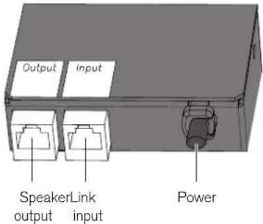
The following diagram gives details of the connections on the back of the loudspeaker:
Use this connection To connect to this
SpeakerLink input The SpeakerLink output of a Meridian controller or another loudspeaker when connecting in a daisy-chain.
SpeakerLink output The SpeakerLink input of another loudspeaker when connecting in a daisy-chain.
Use this connection To connect to this
Power A captive power cord to connect to the RF300 rough-in box power outlet.
Front panel
The following diagram gives details of the front panel:
Item Description
Channel selector Specifies the loudspeaker's role in the system. See Setting up the DSP320.2 DSP Loudspeaker, page 9.
Power switch Controls the mains supply to the loudspeaker.
DSP320.2 DSP Loudspeaker User Guide
Standby indicator
Status Description
Blue Loudspeaker in standby.
White Loudspeaker operating.
At power-up flashes once if IR is off and twice if IR is on.
The loudspeakers are switched on or into standby as appropriate via the SpeakerLink connections by the Meridian system they are connected to.
To configure the IR receiver
Hold down one of the following keys on an MSR remote (not supplied) while powering up the speaker:
Next: Turns on IR; white LED flashes twice.
Previous: Turns off IR; white LED flashes once.
Stop: Resets all to factory settings; white LED flashes 3 times.
Setting up the DSP320.2 DSP loudspeaker
This section explains how to set up the loudspeaker in each of the typical applications.
Using the loudspeaker on the left of the system
- Set the channel selector switch to Left or Centre.
In a multichannel system this applies to all loudspeakers on the left-hand side of the room
Using the loudspeaker on the right of the system
- Set the channel selector switch to Right.
In a multichannel system this applies to all loudspeakers on the right-hand side of the room
Using the loudspeaker to play a mix of left and right audio
- Set the channel selector switch to L+R.
This will play a balanced mix of left and right audio, allowing a single loudspeaker to reproduce all the audio present in a stereo recording. It also provides a useful option for systems
using multiple speakers where the listening area does not have clearly-defined left and right loudspeaker positions.
Using the loudspeaker as a centre channel
Set the channel selector switch to Left or Centre.
Applications
To connect an Audio Core 200 and DSW in a 2.1 system
The DSP320.2 loudspeakers are ideal for a compact home entertainment system based on a Meridian Audio Core 200.
- Connect analogue and digital sources, such as a TV and satellite receiver, to the appropriate inputs on the AC200.
- Connect the lower SpeakerLink output on the Audio Core 200 to the SpeakerLink input of the Master DSP320.2 loudspeaker, using a Meridian SpeakerLink lead.
- Connect the upper SpeakerLink output on the Audio Core 200 to the SpeakerLink input of the DSW subwoofer, using a Meridian SpeakerLink lead.
- Connect the SpeakerLink output from the DSW subwoofer to the Slave DSP320.2 loudspeaker, using a Meridian SpeakerLink lead.
- Set the Channel selector to the Left or Centre position on the left DSP320.2 loudspeaker, to the Right position on the right DSP320.2 loudspeaker, and to the 1+2 position on the DSW subwoofer.
The subwoofer level and crossover are adjustable from the AC200 menus.
DSP320.2 DSP Loudspeaker User Guide

flowchart
graph TD
    A["DSP320.2 – Slave"] --> B["MERIDIAN SPEAKERLINK INPUT OUTPUT"]
    B --> C["Satellite Receiver"]
    C --> D["DIGITAL OUT"]
    D --> E["SpeakerLink leads"]
    F["TV"] --> G["OPTICAL OUT"]
    G --> H["Meridian Audio Core 200"]
    H --> I["ANALOGUE/OPTICAL IN"]
    H --> J["DIGITAL IN"]
    H --> K["SPEAKERLINK IN"]
    H --> L["SpeakerLink leads"]
    M["DSP320.2 – Master"] --> N["MERIDIAN SPEAKERLINK INPUT OUTPUT"]
    N --> O["DSW – Subwoofer"]
    O --> P["MERIDIAN SPEAKERLINK INPUT OUTPUT"]
    P --> Q["SpeakerLink leads"]
    style A fill:#f9f,stroke:#333
    style F fill:#f9f,stroke:#333
    style M fill:#f9f,stroke:#333
12 DSP320.2 DSP Loudspeaker User Guide
To connect a 218 to a single loudspeaker
The DSP320.2 loudspeaker can be used individually with a TV, or in another single loudspeaker system, controlled by a 218 Zone Controller.
- Connect the lower SpeakerLink output (labelled Master) on the 218 Zone Controller to the DSP320.2, using a Meridian SpeakerLink lead.
- Set the Channel selector to the L+R position on the DSP320.2.
- Connect the Network socket from the 218 Zone Controller to a LAN network connection on your Router, using CAT5 cable.
- Connect the optical output of the TV to the optical input of the 218.
Audio can be streamed to the system and controlled via the Network socket on the 218.

flowchart
graph TD
    A["218 Zone Controller"] --> B["SPEAKERLINK OUT"]
    A --> C["OPTICAL IN"]
    A --> D["NETWORK"]
    B --> E["SpeakerLink lead"]
    C --> E
    D --> E
    E --> F["MERIDIAN SPEAKERLINK INPUT OUTPUT"]
    G["DSP320.2"] --> H["OPTICAL OUT"]
    H --> I["TV"]
    J["Router"] --> K["Network"]
To use DSP320.2 loudspeakers in a Meridian Digital Theatre
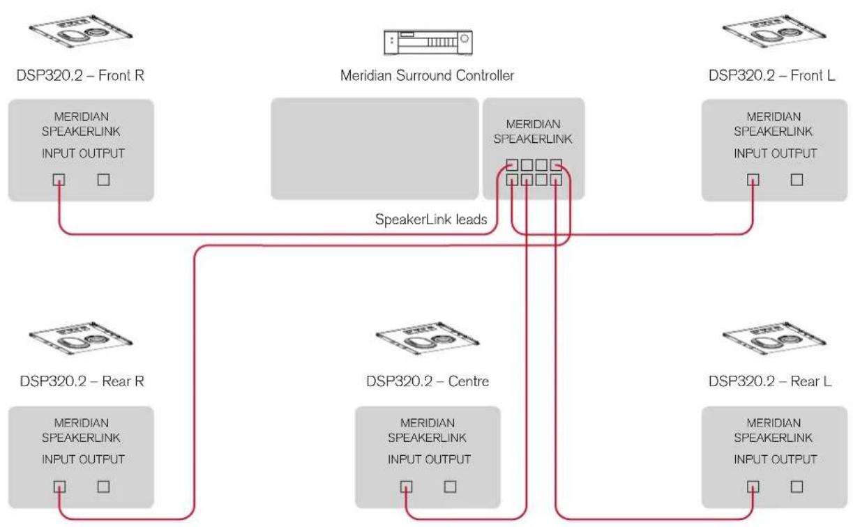
DSP320.2 loudspeakers are ideal as the front, rear, and centre loudspeakers in a Meridian Digital Theatre, in conjunction with a Meridian Digital Surround Controller such as the G65. The following diagram shows how to connect the loudspeakers using "home run" wiring.
- Connect the L+R SpeakerLink output on the lower row (labelled Master) of the G65 to the front left DSP320.2 loudspeaker, using a Meridian SpeakerLink lead.
- Connect the appropriate SpeakerLink outputs on the G65 to each of the remaining loudspeakers, using Meridian SpeakerLink leads.
- Make sure the Channel selector on each DSP320.2 is set to the Left or Centre position on the left and centre loudspeakers and to the Right position on the right loudspeaker.
Alternatively you can connect the loudspeakers using "daisy chain" wiring: connect the front and rear L loudspeakers to the G65, and then link each pair of loudspeakers together by connecting the output from the L loudspeaker to the input of the R loudspeaker.
DSP320.2 DSP Loudspeaker User Guide
flowchart
graph TD
    A["DSP320.2 – Front R"] --> B["MERIDIAN SPEAKERLINK INPUT OUTPUT"]
    C["Meridian Surround Controller"] --> D["MERIDIAN SPEAKERLINK"]
    E["DSP320.2 – Front L"] --> F["MERIDIAN SPEAKERLINK INPUT OUTPUT"]
    G["DSP320.2 – Rear R"] --> H["MERIDIAN SPEAKERLINK INPUT OUTPUT"]
    I["DSP320.2 – Centre"] --> J["MERIDIAN SPEAKERLINK INPUT OUTPUT"]
    K["DSP320.2 – Rear L"] --> L["MERIDIAN SPEAKERLINK INPUT OUTPUT"]
    B --> M["SpeakerLink leads"]
    D --> M
    F --> M
    H --> M
    J --> M
    L --> M
To use DSP320.2 loudspeakers with a Meridian 271 and a non-Meridian AVR
The Meridian 271 Digital Theatre Controller acts as an interface between a non-Meridian surround-sound processor (AVR) and Meridian DSP loudspeakers. This is a 5.1 system based on an AVR with unbalanced analogue outputs. The same connection method can be used for systems with more channels, such as those which support immersive audio formats.
- Set the channel selector switch on each of the DSP320.2 loudspeakers according to its role within the system.
- Connect the DSP320.2 loudspeakers to the SpeakerLink outputs on the 271 as appropriate for their position in the system. By convention, loudspeakers on the left-hand side of a Meridian system and the centre-channel loudspeaker use odd channel numbers (1, 3, 5, etc.) and loudspeakers on the right-hand side of the system use even numbers (2, 4, 6, etc.)
- Connect the unbalanced analogue outputs from the AVR to the unbalanced analogue inputs on the 271, using RCA phono cables.
DSP320.2 DSP Loudspeaker User Guide

flowchart
graph TD
    A["DSP320.2 – Front R"] --> B["MERIDIAN SPEAKERLINK INPUT OUTPUT"]
    C["271 Digital Theatre Controller"] --> D["ANALOGUE INPUT UNBALANCED"]
    D --> E["SpeakerLink leads"]
    E --> F["DSP320.2 – Centre"]
    G["DSP320.2 – Front L"] --> H["MERIDIAN SPEAKERLINK INPUT OUTPUT"]
    I["DSP320.2 – Centre"] --> J["MERIDIAN SPEAKERLINK INPUT OUTPUT"]
    K["DSP320.2 – Centre"] --> L["MERIDIAN SPEAKERLINK INPUT OUTPUT"]
    M["DSP320.2 – Centre"] --> N["MERIDIAN SPEAKERLINK INPUT OUTPUT"]
    O["DSP320.2 – Centre"] --> P["MERIDIAN SPEAKERLINK INPUT OUTPUT"]
    Q["DSP320.2 – Centre"] --> R["MERIDIAN SPEAKERLINK INPUT OUTPUT"]
    S["DSP320.2 – Centre"] --> T["MERIDIAN SPEAKERLINK INPUT OUTPUT"]
    U["DSP320.2 – Centre"] --> V["MERIDIAN SPEAKERLINK INPUT OUTPUT"]
    W["DSP320.2 – Centre"] --> X["MERIDIAN SPEAKERLINK INPUT OUTPUT"]
    Y["DSP320.2 – Centre"] --> Z["MERIDIAN SPEAKERLINK INPUT OUTPUT"]
    AA["DSP320.2 – Centre"] --> AB["MERIDIAN SPEAKERLINK INPUT OUTPUT"]
    AC["DSP320.2 – Centre"] --> AD["MERIDIAN SPEAKERLINK INPUT OUTPUT"]
    AE["DSP320.2 – Centre"] --> AF["MERIDIAN SPEAKERLINK INPUT OUTPUT"]
    AG["DSP320.2 – Centre"] --> AH["MERIDIAN SPEAKERLINK INPUT OUTPUT"]
    AI["DSP320.2 – Centre"] --> AJ["MERIDIAN SPEAKERLINK INPUT OUTPUT"]
    AK["DSP320.2 – Centre"] --> AL["MERIDIAN SPEAKERLINK INPUT OUTPUT"]
    AM["DSP320.2 – Centre"] --> AN["MERIDIAN SPEAKERLINK INPUT OUTPUT"]
    AO["DSP320.2 – Centre"] --> AP["MERIDIAN SPEAKERLINK INPUT OUTPUT"]
    AQ["DSP320.2 – Centre"] --> AR["MERIDIAN SPEAKERLINK INPUT OUTPUT"]
    AS["DSP320.2 – Centre"] --> AT["MERIDIAN SPEAKERLINK INPUT OUTPUT"]
    AU["DSP320.2 – Centre"] --> AV["MERIDIAN SPEAKERLINK INPUT OUTPUT"]
    AW["DSP320.2 – Centre"] --> AX["MERIDIAN SPEAKERLINK INPUT OUTPUT"]
    AY["DSP320.2 – Front L"] --> AZ["MERIDIAN SPEAKERLINK INPUT OUTPUT"]
    BA["DSP320.2 – Front L"] --> BB["MERIDIAN SPEAKERLINK INPUT OUTPUT"]
    BC["DSP320.2 – Front L"] --> BD["MERIDIAN SPEAKERLINK INPUT OUTPUT"]
    BE["DSP320.2 – Front L"] --> BF["MERIDIAN SPEAKERLINK INPUT OUTPUT"]
    BG["DSP320.2 – Front L"] --> BH["MERIDIAN SPEAKERLINK INPUT OUTPUT"]
    BI["DSP320.2 – Front L"] --> BJ["MERIDIAN SPEAKERLINK INPUT OUTPUT"]
    BK["DSP320.2 – Front L"] --> BL["MERIDIAN SPEAKERLINK INPUT OUTPUT"]
    BM["DSP320.2 – Front L"] --> BN["MERIDIAN SPEAKERLINK INPUT OUTPUT"]
    BO["DSP320.2 – Front L"] --> BP["MERIDIAN SPEAKERLINK INPUT OUTPUT"]
    BQ["DSP320.2 – Centre"] --> BR["MERIDIAN SPEAKERLINK INPUT OUTPUT"]
    BS["DSP320.2 – Centre"] --> BT["MERIDIAN SPEAKERLINK INPUT OUTPUT"]
    BU["DSP320.2 – Centre"] --> BV["MERIDIAN SPEAKERLINK INPUT OUTPUT"]
    BW["DSP320.2 – Centre"] --> BX["MERIDIAN SPEAKERLINK INPUT OUTPUT"]
    BYD["DSP320.2 – Centre"] --> BZ["MERIDIAN SPEAKERLINK INPUT OUTPUT"]
    CA["DSP320.2 – Centre"] --> CB["MERIDIAN SPEAKERLINK INPUT OUTPUT"]
    CC["DSP320.2 – Centre"] --> CD["MERIDIAN SPEAKERLINK INPUT OUTPUT"]
    CE["DSP320.2 – Centre"] --> CF["MERIDIAN SPEAKERLINK INPUT OUTPUT"]
    CG["DSP320.2 – Centre"] --> CH["MERIDIAN SPEAKERLINK INPUT OUTPUT"]
    CI["DSP320.2 – Centre"] --> CJ["MERIDIAN SPEAKERLINK INPUT OUTPUT"]
    CK["DSP320.2 – Centre"] --> CL["MERIDIAN SPEAKERLINK INPUT OUTPUT"]
    CM["DSP320.2 – Centre"] --> CN["MERIDIAN SPEAKERLINK INPUT OUTPUT"]
    CO["DSP320.2 – Centre"] --> CP["MERIDIAN SPEAKERLINK INPUT OUTPUT"]
    COQ["DSP320.2 – Centre"] --> CQ["MERIDIAN SPEAKERLINK INPUT OUTPUT"]
    CX["DSP320.2 – Centre"] --> CY["MERIDIAN SPEAKERLINK INPUT OUTPUT"]
    CXQ["DSP320.2 – Centre"] --> CZ["MERIDIAN SPEAKERLINK INPUT OUTPUT"]
    CXQX["DSP320.2 – Centre"] --> DA["MERIDIAN SPEAKERLINK INPUT OUTPUT"]
    CXQY["DSP320.2 – Centre"] --> DB["MERIDIAN SPEAKERLINK INPUT OUTPUT"]
    CXQZ["DSP320.2 – Centre"] --> DC["MERIDIAN SPEAKERLINK INPUT OUTPUT"]
    CXQXZ["DSP320.2 – Centre"] --> DE["MERIDIAN SPEAKERLINK INPUT OUTPUT"]
    CXQXZ["DSP320.2 – Centre"] --> DF["MERIDIAN SPEAKERLINK INPUT OUTPUT"]
RS232 commands
RS232 is one of several interfaces carried by the Meridian Speakerlink RJ45/Cat5 connection. The Meridian Distributor and the Meridian AC12 make this interface available on a standard RS232 connector.
Port settings
9600 Baud, 8 data bits, 1 stop bit, no parity, no flow control
Command format
RS232 commands consist of ASCII characters which are case sensitive. Some commands require parameters, so these are followed by additional characters. All commands are terminated with a carriage return.
For example, to change the volume level to 45, the command is:
VN45
This will cause the loudspeaker to change its volume and respond with:
Volume 45
Non-volatile configuration and reset
Some of the RS232 commands described in this document produce non-volatile (lasting) configuration changes in the DSP loudspeaker. These commands should be used carefully because they may affect the sound and operation of the loudspeaker without giving any obvious external indications.
An RS232 command is provided to reset the loudspeaker to its default configuration. The loudspeaker may also be reset by powering-up with the stop key pressed on the MSR+ remote control. This is confirmed by three flashes from the white LED on the loudspeaker.
Loudspeaker control commands
These commands are used for everyday control of a pair loudspeakers such as by a control system connected to the master loudspeaker through a Meridian Distributor.
Command Type Code Parameters Meaning Function Example
Response
| Source Selection | CD None, sb | 1 | Select source Select source 0 CD | 65 |
| RD None, sb | 1 | Select source Select source 1 Radio | 65 | |
| LP, AX or MS None, sb | 1 | Select source Select source 2 SLS | 65 | |
| TV None, sb | 1 | Select source Select source 3 TV | 65 | |
| TA, T1 or IP None, sb | 1 | Select source Select source 4 iPod | 65 | |
| T2 or SA None, sb | 1 | Select source Select source 5 SAT | 65 | |
| CR or DC None, sb | 1 | Select source Select source 6 Disc | 65 | |
| CB None, sb | 1 | Select source Select source 7 Cable | 65 | |
| TX or DV None, sb | 1 | Select source Select source 8 DVD | 65 | |
| V1 or US None, sb | 1 | Select source Select source 9 USB | 65 | |
| V2 or MX None, sb | 1 | Select source Select source 10 | Mixer 65 | |
| LD or GA None, sb | 1 | Select source Select source 11 | Game 65 | |
| SB None | Standby | Standby | ||
| MU None | Mute | Mute |
| Command Type Code Parameters Meaning Function Example | ||||
| Response | ||||
| Volume | VN ## | Volume number Go to volume number | Volume 65 | |
| VP None | Volume Plus Increase volume Volume 66 | |||
| VM None | Volume Minus Decrease volume Volume 64 | |||
| Audio Effects | TN ±##.# | Treble Number Go to Treble number Treble + 6.0 | ||
| BN ±##.# | Bass number | Go to bass number | Bass + 5.0 | |
| LN ±## | Left number | Go to balance setting | Left 3 | |
| RN ±## | Right number | Go to balance setting | Right 6 | |
| P+ None | Phase + | Phase + | Phase + | |
| P- None | Phase - | Phase - | Phase - | |
| Display | DI ON, OFF | Display | Light on or off | Light On |
Source control commands
These commands allow control of a Meridian source connected to the master loudspeaker. No response is given on RS232.
Code Meaning/Function
| PL | Play |
| ST | Stop |
| PS | Pause |
| RP | Repeat |
| NE | Next |
| PR | Previous |
| FF | Fast Forward |
| FB | Fast Back |
| MP | Menu up |
| MM | Menu down |
| ML | Menu left |
| MR | Menu right |
| N0 - N9 | Number keys |
| SR | Store |
| CL | Clear |
Configuration
These commands affect only the connected loudspeaker. They configure features of the loudspeaker that would otherwise be inaccessible without a SpeakerLink capable controller.
The settings made are non-volatile (ie they remain when the loudspeaker is powered down). These settings can override commands from a SpeakerLink controller, so they should be used with caution. To restore SpeakerLink control, choose the SL parameter.
| Command Type Code Parameters Meaning Example Response | |||
| IR receiver2 | IR ON | Turns on IR receiver eye IR on | |
| OFF | Turns off IR receiver eye IR off | ||
| Speaker position | BO SL | Boundary EQ controlled by Speakerlink NV Boundary Speakerlink | |
| FR | Free-space equalization3 NV Boundary Free | ||
| WA | Wall equalization NV Boundary Wall | ||
| SH | Shelf equalization NV Boundary Shelf | ||
| CO | Corner equalization NV Boundary Corner | ||
| Subwoofer | SW SL | Subwoofer Controlled By Speakerlink NV Subwoofer | |
| OFF | Subwoofer Off NV Subwoofer Off | ||
| 1 | Subwoofer Crossover 1 NV Subwoofer Sub 1 | ||
| 2 | Subwoofer Crossover 1 NV Subwoofer Sub 2 | ||
| WI | Subwoofer Wideband NV Subwoofer Speakerlink | ||
| SG +/-## | Subwoofer Gain4 NV Sub Gain 12 | ||
| Command Type Code Parameters Meaning Example Response | ||||
| Audio Effects | EA SL, ON, OFF | Enhanced Bass Alignment (EBA) | NV EBA On | |
| EC SL, OFF, MIN, MED, MAX | Enhanced Boundary Control (EBC) | NV EBC Med | ||
| RH ### | Room Height in cm for EBC5 | NV EBA Room Height 210cm | ||
| CE SL, OFF, MIN, MED, MAX | Centre Elevation NV Centre Elevation Min | |||
| LO SL, ON, OFF | Loudness NV Loudness Speakerlink | |||
| Cm6 | ON, OFF | Centre mode NV Left or Centre | ||
| Mm SL, MU, MO | Music/Movie Mode7 | NV Music Mode | ||
| Status/Reset | NV None | Non-volatile A list of the non-volatile settings | ||
| RS | Non-volatile Reset Resets all non-volatile settings | |||
Utility/diagnostic
Code Meaning Response
| IR2 | Infra-red receiver status | IR on/IR off |
| Cm | Centre mode status A text description of the status | |
| ID | Identity A list of product name and versions | |
| !R | Reset Bye | |
Notes
- When in standby, a source selection command may be followed by sb (e.g. CDsb). This allows e.g. a connected Distributor to change source, but the speakers will remain in standby.
- Available only on Meridian DSP320, DSP520 and DSP640.
- Free-space equalization is not available on in-wall loudspeakers.
-
The non-volatile subwoofer gain is only used when the non-volatile subwoofer setting is not SL. The range is -15 to +15 in 1dB steps.
-
The non-volatile room height is only used when the non-volatile EBC setting is not SL. The range is 150 to 400cm in 1cm steps.
- Centre mode applies only to DSP520.2 and DSP640.2
- Music/Movie mode applies only to the Meridian DSW.
Index
A
applications
Audio Core 200 and DSW in a 2.1
system 10
connecting a 218 to a single loudspeaker 12
connecting to a Meridian 271 and a non-Meridian AVR 16
Meridian Digital Theatre 14
AVR, connecting to 16
B
back panel 7
back panel connections 7
balanced outputs 7
C
channel selector 7
L+R 9
Left or Centre 9
Right 9
components 4
controlling the loudspeaker 2
E
Enhanced Bass Alignment (EBA) 1
F
front panel 7
G
grille, fitting 6
|
indicators 8
installation 4
connecting the loudspeaker 5
fitting the scrim and grille 6
identifying the cables 4
preparation 4
M
Meridian 218, connecting to 12
Meridian 271, connecting to 16
Meridian Audio Core 200, connecting to 10
Meridian Digital Theatre 14
P
power input 7
power switch 7
DSP320.2 DSP Loudspeaker User Guide
R
registration iv
RS232 commands 18
configuration 22
loudspeaker control 19
source control 21
utility/diagnostic 24
S
setting up 9
as a centre channel 9
on the left of the system 9
on the right of the system 9
to play a mix of left and right audio 9
soundbar applications 12
SpeakerLink input 7
SpeakerLink output 7
specifications 3
status indicators 8
switches, setting 6

- DSP320.2 DSP LOUDSPEAKER
- USER GUIDE
- ii DSP320.2 DSP Loudspeaker User Guide
- Important safety instructions
- Safety warnings
- Climate
- To avoid overheating
- To avoid interference
- Radio interference
- Copyright and acknowledgements
- Designed and manufactured in the UK
- Product registration
- DSP320.2 DSP Loudspeaker User Guide
- Contents
- Introduction
- Acoustics
- On-board DSP
- Enhanced Bass Alignment (EBA)
- Enhancement technologies
- Construction
- DSP320.2 DSP Loudspeaker User Guide
- Controlling the loudspeaker
- Specifications
- Audio input
- Audio output
- Drivers
- Amplifiers
- Performance
- Front panel
- Physical
- Power
- Protection
- DSP320.2 DSP Loudspeaker User Guide
- Installing the DSP320.2 DSP Loudspeaker
- Prepare the loudspeaker for installation
- Identify the cables
- Install the loudspeaker
- Set the front-panel switches
- Fit the grille – if required
- Front and back panel
- Connections
- Use this connection To connect to this
- Item Description
- Standby indicator
- Status Description
- To configure the IR receiver
- Setting up the DSP320.2 DSP loudspeaker
- Using the loudspeaker on the left of the system
- Using the loudspeaker on the right of the system
- Using the loudspeaker to play a mix of left and right audio
- Using the loudspeaker as a centre channel
- Applications
- To connect an Audio Core 200 and DSW in a 2.1 system
- DSP320.2 DSP Loudspeaker User Guide
- To connect a 218 to a single loudspeaker
- To use DSP320.2 loudspeakers in a Meridian Digital Theatre
- To use DSP320.2 loudspeakers with a Meridian 271 and a non-Meridian AVR
- RS232 commands
- Port settings
- Command format
- Non-volatile configuration and reset
- Loudspeaker control commands
- Source control commands
- Configuration
- Utility/diagnostic
- Notes
- Index
- A
- B
- C
- E
- F
- G
- |
- M
- P
- R
- S
Brand : MERIDIAN
Model : DSP320.2
Category : Loudspeaker