
EasyUSB MicPOD I/O - Desk Phone Vaddio - Free user manual and instructions
Find the device manual for free EasyUSB MicPOD I/O Vaddio in PDF.


| Product Type | USB Microphone Pod / Desk Phone |
| Brand | Vaddio |
| Model | EasyUSB MicPOD I/O |
| Dimensions (H x W x D) | Approximately 2.5 x 4.5 x 4.5 inches |
| Weight | Approximately 1.2 lbs |
| Power Source | USB bus-powered (5V, 500mA) |
| Connectivity | USB 2.0 (Type-A connector) |
| Microphone Type | Omnidirectional electret condenser |
| Frequency Response | 100 Hz - 10 kHz |
| Compatible Operating Systems | Windows, macOS, Linux (UAC compliant) |
| Key Features | Plug-and-play, mute button, built-in echo cancellation |
| Maintenance and Cleaning | Wipe with a soft, dry cloth. Avoid liquids. |
| Safety Precautions | Do not expose to moisture or extreme temperatures. |
| Spare Parts and Repairability | No user-serviceable parts. Contact Vaddio support for repairs. |
| Warranty | Limited 2-year warranty |
| Included Accessories | USB cable, quick start guide |
Frequently Asked Questions - EasyUSB MicPOD I/O Vaddio
User questions about EasyUSB MicPOD I/O Vaddio
0 question about this device. Answer the ones you know or ask your own.
Ask a new question about this device
Download the instructions for your Desk Phone in PDF format for free! Find your manual EasyUSB MicPOD I/O - Vaddio and take your electronic device back in hand. On this page are published all the documents necessary for the use of your device. EasyUSB MicPOD I/O by Vaddio.
USER MANUAL EasyUSB MicPOD I/O Vaddio
natural_image
Two white and black spherical electronic devices with vertical wires, no visible text or symbols.
natural_image
Top-down view of a black circular electronic device with a mesh grille and 'verdico' logo on the top (no text or symbols on body)TRIO Table Microphone Array
TRIO Ceiling Mic Array and Electronics Module (shown with black mic and cable)

natural_image
Black rectangular electronic device with a coiled cable and a spherical connector (no visible text or symbols)Inside Front Cover - Blank
TABLE OF CONTENTS
Overview: 4
Unpacking....5
Equipment Descriptions and Call-outs 6
TRIO MIC I/O Interface....6
Diagram: TRIO Mic I/O Front Panel 6
Image: TRIO MIC I/O Rear Panel....6
TRIO Table Mic Array 7
Diagram: Top View of TRIO Table Mic Array 7
Diagram: Bottom View of Top View of TRIO Table Mic Array....7
TRIO Ceiling Mic Array 8
Diagram: TRIO Ceiling Mic Interface Module 8
Diagram: TRIO Ceiling Mic Array Head....9
TRIO MIC I/O System Configuration and Programming 9
Diagram: Professional Audio Mixer Connection Diagram with TRIO Mic I/O.... 10
Step-by-Step Installation Instructions.... 11
TRIO Mic I/O Installation: 11
Diagram: Basic System Connections 11
TRIO Table and Ceiling Mic Array Installation 12
Diagram: TRIO Table Mic Installation Diagram (bottom view) 12
Warranty Information: 13
Compliance and CE Declaration of Conformity 14
Technical Specifications 15
Appendix 1: Connectors Pin Outs 15
OVERVIEW:
Vaddio's TRIO Microphone solution allows echo cancellation to be added to any professional audio mixer for conferencing applications. No complex DSP programming required.

Vaddio TRIO Table and Ceiling Microphone Arrays incorporate SmartMic technology along with built-in DSPs for the ultimate in simple control and maximum performance. The technology integrates automatic microphone mixing, wideband echo cancellation, noise reduction, and automated gain control into the microphones and eliminates the need for super expensive, hard to program and operate conferencing mixers.
Pair the TRIO microphones with the TRIO MIC I/O interface device to provide four balanced line level output channels that easily connect to a room's audio mixer. A single Echo Cancelling Reference input to the TRIO MICI/O completes the interface with the audio mixer.
The TRIO microphone system solution is comprised of the following devices:
• TRIO Mic I/O Interface (above):
The TRIO Mic I/O provides an audio breakout interface for use with Vaddio's TRIO Microphones. Seamlessly interface up to four (4) TRIO Mics to a professional audio mixer. The TRIO MIC I/O segments each microphone device into a line level balanced output for connection to audio input of a professional audio mixer. A single AEC Reference input is connected to the TRIO Mic I/O from the room mixer to complete the installation for echo cancelling microphones.
• TRIO Table Microphone Array:
The TRIO Table Microphone Array is an attractive echo cancelling table microphone with 360° audio coverage pattern and reach of approximately 12' (3.66m) in radius. Three cardioid microphones and built-in DSP comprise the device. The TRIO Table Microphone connects to the TRIO Mic I/O with single home run of Cat-5 cable providing audio and power.
- TRIO Ceiling Microphone Array: The echo cancelling ceiling microphone with 360° audio pick-up pattern formed by a 3-microphone element array. It includes a plenum rated interface box with a microphone head on adjustable 36" drop cable. The TRIO Ceiling Microphones are offered in both black and white versions.

natural_image
Three hanging objects: a circular black disc, a white spherical object with black bands, and a dark spherical object (no text or symbols visible)Intended Use:
Before operating the device, please read the entire manual thoroughly. The system was designed, built and tested for use indoors, and with the provided power supply and cabling. The use of a power supply other than the one provided or outdoor operation has not been tested and could damage the device and/or create a potentially unsafe operating condition.
Important Safeguards:
Read and understand all instructions before using. Do not operate any device if it has been dropped or damaged. In this case, a Vaddio technician must examine the product before operating. To reduce the risk of electric shock, do not immerse in water or other liquids and avoid extremely humid conditions. Do not connect Ethernet or Power over Ethernet (POE) cables directly to the RJ-45 ports on the device as damage may be the result.

Use only the power supply provided with the system. Use of any unauthorized power supply will void any and all warranties.

Please do not use "pass-thru" type RJ-45 connectors. These pass-thru type connectors do not work well for professional installations and can be the cause of intermittent connections which can result in the RS-232 control line failing and locking up. For best results please use standard RJ-45 connectors and test all cables for proper pin-outs prior to use.
Save These Instructions:
The information contained in this manual will help you install and operate your product. If these instructions are misplaced, Vaddio keeps copies of Specifications, Installation and User Guides and most pertinent product drawings for the Vaddio product line on the Vaddio website. These documents can be downloaded from www.vaddio.com free of charge.
UNPACKING
All components within the shipping box are individually packaged as described in the sections below. Carefully remove all parts included in the individual packaging.
TRIO Mic I/O
999-8535-000: TRIO Mic I/O (North America)
Pack-out includes:
• One (1) TRIO Mic I/O
• One (1) 18 VDC 2.75A Power Supply with North American Power Cord
- Five (5) 3-Pin 5mm Phoenix-type Terminal Plug
- Documentation
TRIO Mic I/O
999-8535-001: TRIO Mic I/O – (International)
Pack-out includes:
• One (1) TRIO Mic I/O
• One (1) 18 VDC 2.75A Power Supply
- Five (5) 3-Pin 5mm Phoenix-type Terminal Plug
• One (1) UK Power Cord
• One (1) Euro Power Cord
- Documentation
TRIO Table Microphone
999-8850-000: TRIO Table Microphone—(Worldwide)
Pack-out includes:
• One (1) TRIO Table Microphone
• One (1) 25 foot Cat-5 Cable
- Pointer Manual
TRIO Ceiling Microphone (White Version)
999-8860-000: TRIO Ceiling Microphone (White Version)
Pack-out includes:
• One (1) TRIO Ceiling Microphone with Interface Box
• One (1) Tile Support Bridge
- Documentation
TRIO Ceiling Microphone (Black Version)
999-8865-000: TRIO Ceiling Microphone (Black Version)
Pack-out includes:
• One (1) TRIO Ceiling Microphone with Interface Box
• One (1) Tile Support Bridge
Documentation


natural_image
Close-up of a black circular electronic device with a mesh grille and ventilation slots (no visible text or symbols)
Bundles:
TRIO I/O and Microphone system bundles have been preconfigured for convenience. These systems are as follows:
Bundle A - 999-8800-000/001: TRIO I/O and two (2) White Ceiling Mic Arrays (001 suffix for Int'l)
Bundle B - 999-9910-000/001: TRIO I/O and four (4) White Ceiling Mic Arrays (001 suffix for Int'l)
Bundle C - 999-8820-000/001: TRIO I/O and two (2) Table Mic Arrays (001 suffix for Int'l)
Bundle D - 999-8830-000/001: TRIO I/O and four (4) Table Mic Arrays (001 suffix for Int'l)
EQUIPMENT DESCRIPTIONS AND CALL-OUTS
TRIO MIC I/O Interface
The TRIO Mic I/O is an audio breakout interface for the TRIO Microphones. The interface provides power and audio over Cat-5 to the TRIO MIC and terminates into a balanced line level audio source for connection to a room's audio mixer.
Diagram: TRIO Mic I/O Front Panel

1) Power LED: Blue LED power indicator.
Image: TRIO MIC I/O Rear Panel

1) Power: 18 VDC, 2.75 Amp power supply input.
2) Mic Port: Four Mic Ports on RJ-45 connectors providing power and audio over single Cat-5 cable to the connected TRIO devices.
3) AEC Reference Input: Acoustic Echo Cancellation (AEC) Reference input channel. A balanced line level input. AEC reference signal should be a duplicate audio signal from the connected mixer that represents the audio being sent to the loudspeakers within the room. A proper AEC reference is required for the TRIO Microphones to work properly in a conferencing application.
4) Line Outputs: Balanced line level output of the TRIO Microphones for connection to the room's audio mixer. This signal will be echo canceled. An automatic microphone mixing function should be employed on the room's audio mixer if multiple TRIO microphones are used in the installation.
TRIO Table Mic Array
Diagram: Top View of TRIO Table Mic Array
1) Microphone Elements x 3:
The three (3) high definition cardioid microphone elements are evenly space at 120° providing 360° circular coverage around the pod.
2) Really Cool Logo

natural_image
Top-down view of a black circular speaker grille with labeled components (no text or symbols beyond labels)Diagram: Bottom View of Top View of TRIO Table Mic Array

1) Mic Port:
RJ-45 Connection port that is home ran to the TRIO MIC I/O Interface via up to 100' (30.48m) of Cat-5 cable.
2) Cable Management:
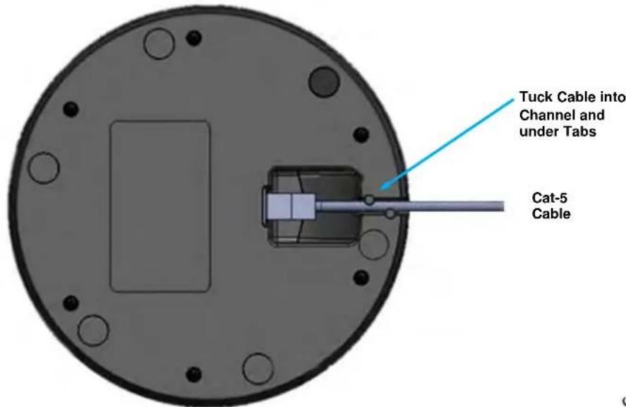
A channel with cable tabs is for routing Cat-5 cable from the mic while allowing the mic to sit flat on any surface.
3) Rubber Feet:
Six rubber feet are evenly spaced around the radius on the bottom of the TRIO Mic to prevent the mic from sliding around on the table, which can be annoying to the far-end.
TRIO Ceiling Mic Array
The Ceiling Interface Module is designed for above ceiling installation requiring plenum rating. A removable top cover allows user access to connect required cables. The assembly can also be mounted below ceiling securing with standard anchors with the pre-drilled holes within the ears.
Diagram: TRIO Ceiling Mic Interface Module
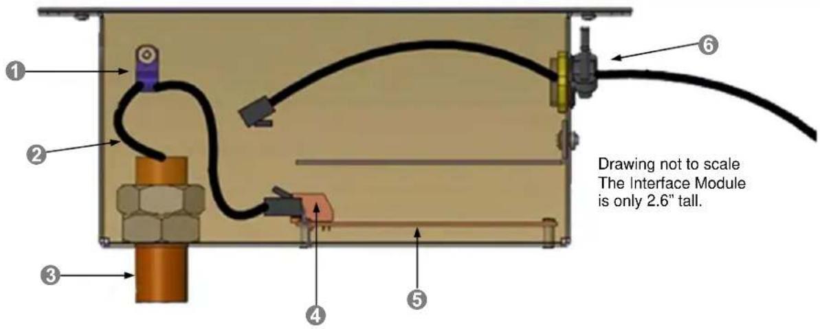
1) Strain Relief Clamp:
The clamp is an adjustable cable clamp allowing the installer to fix the ceiling mic array head at the desired distance from ceiling. The cable is 36" and can be shortened simply by leaving more cable in the box tied around the clamp.
2) Array Head Drop Cable:
A 36" cable terminated with a RJ-45 jack provides the connection of the ceiling mic array head to the processing board housed in the Ceiling Interface Module.
3) Feed-Through Coupler:
A 5/8" threaded feed through coupler is used to feed the cable into the Ceiling Interface Module. The coupler extends through a ceiling tile and ceiling tile brace or through a drywall hole in the ceiling.

Note: Keep the pilot hole in the tile or drywall as close to 5/8" as possible.
4) Array Head Connector:
An RJ-45 plug secures the connection of the ceiling mic array head with the internal processing board. Connectors are clearly marked. "IN FROM MIC" and "OUT TO MIXER"
5) Internal PCBA:
The board that supports the mic element providing DSP functions and Acoustic Echo Cancellation is located in the ceiling module.
6) TRIO Mic Port & Cable:
A second RJ-45 jack is located on the processing board internal to the Ceiling Interface Module. This is the TRIO Mic Port for connection of the device to the TRIO MIC I/O via a standard Cat- 5 cable. The cable exits the Ceiling Interface Module via a standard conduit connector.
Diagram: TRIO Ceiling Mic Array Head
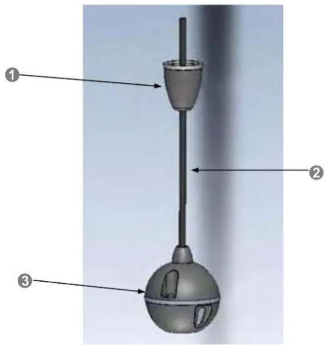
1) Trim Cover: The trim cover screws onto the 5/8" feed-through coupler on the Ceiling Interface Module providing a dressed appearance for ceiling installations. An escutcheon ring is provided to trim out the hole.

Remember to keep the pilot hole in the tile or drywall as close to 5/8" as possible
2) Array Head Drop Cable: A 36" cable terminated with a RJ-45 jack and provides the connection of the ceiling mic array head with the processing board housed in the Ceiling Interface Module.
3) Array Head: The array head is 2.5" diameter microphone that provides 360 degree sound pick-up coverage.
TRIO MIC I/O SYSTEM CONFIGURATION AND PROGRAMMING
The TRIO Mic I/O is a plug & play device that requires no programming. However, a there are a few recommendations when interfacing to the audio mixer:
TRIO Mic Audio Levels: The recommendation is to set the input gain on the external audio mixer level during speech to peak at @ +6dBu.
AEC Reference Audio Level: The AEC Reference output level from the audio mixer going to the TRIO MIC I/O should be set at a nominal level @0dBu. An extremely low level AEC Reference (<-20dBu) could impact the AEC performance it the TRIO mic arrays.
The Room's Audio Mixer: The TRIO Microphones are recommended to be used with professional audio mixers that have automatic microphone mixing functions. The automatic microphone mixer will yield better far-end audio quality when multiple TRIO Microphones are used within the same room installation.
Diagram: Professional Audio Mixer Connection Diagram with TRIO Mic I/O
The diagram below depicts a typical deployment of the TRIO MIC I/O with a professional audio mixer in a conference room application. TRIO mic arrays are connected to the TRIO MIC I/O interface. The TRIO MIC I/O outputs are connected to the input channels of the professional audio mixer. The AEC reference input (required for proper operation) is connected to an output on the mixer (far end audio).

STEP-BY-STEP INSTALLATION INSTRUCTIONS
TRIO Mic I/O Installation:
Locate the TRIO Mic I/O a centralized location near the room's audio mixer. Follow steps below to install devices:
Diagram: Basic System Connections

STEP 1:
Connect the provided 18 VDC Power Supply to the TRIO Mic I/O.
STEP 2:
Connect the Cat-5 cable between the TRIO MIC I/O and the TRIO Ceiling or Table Mic Array
STEP 3:
Connect the balanced line level outputs from the TRIO Mic I/O to the room's audio mixer.
STEP 4:
Connect the line level output from the room's audio mixer to the AEC Reference input on the TRIO Mic I/O.
Optional Accessories - The TRIO Mic I/O has an optional accessory kit:
- Rack Mounting Kit: The rack kit provides a method for the TRIO Mic I/O to be installed in a 1RU space within a rack. The Rack Kit includes two rack ears (one long and one short). The rack ears are mounted on the sides of the TRIO Mic I/O using the existing screws included on the device.

natural_image
Exterior view of a black industrial server rack unit (no visible text or symbols)TRIO TABLE AND CEILING MIC ARRAY INSTALLATION
Trio Table Mic
1) Pick up the TRIO table mic and flip it over to the bottom side (low degree of difficulty)..
2) Plug in RJ-45 cable originating TRIO MIC I/O Interface.
3) Align RJ-45 cable into cable tray for exiting out enclosure and place unit back on table.
Diagram: TRIO Table Mic Installation Diagram (bottom view)
TRIO Ceiling Mic Array
For some of the most obvious reasons, a ladder is required to install the TRIO Ceiling Mic Arrays. Safety comes first, so please use safe tools, ladders and install practices. Measure twice cut once...

1) Identify desired location of the ceiling tile for the Trio Ceiling Mic to be installed. Use the Tile Support Brace as a template. Measure, then cut a 5/8 to 3/4" hole into ceiling tile - be very accurate with cutting the hole. Score the front of the tile to get a clean cut.
2) Install the included Tile Support Brace by aligning ceiling tile hole with openings on the bridge. There are hanging holes along the folded up edges of the tile brace so that it can be tied to the building structure.
3) Remove top cover on the Ceiling Mic Array Interface Module.
4) Place the Ceiling Mic Interface Module on the installed Tile Support Brace with the feed-through coupler extending through the hole in brace and ceiling tile.
5) Install the Microphone Array head by feeding drop cable through the 5/8" coupler and plug into the RJ-45 connector labeled IN FROM MIC on the interior of the Ceiling Interface Module. Make sure trim cover and the 1.5" white plastic trim ring is slid over the MicPOD RJ-45 Jack prior to feeding drop cable through coupler. Adjust hanging length of Mic Array Head by placing service loop into strain relief clamp. Lock relief clamp once desired ceiling hanging height is achieved. Screw trim cover onto feed-through coupler until flush with the 1.5" white plastic trim ring and the ceiling tile.
6) Route Cat-5's RJ-45 connector originating from the TRIO MIC I/O through the conduit coupler on the end of the Ceiling Interface Module. Connect the Cat-5 cable to the internal connector labeled OUT TO MIXER. Re-attach the lid cover removed in step 3.
WARRANTY INFORMATION: (See Vaddio Warranty, Service and Return Policies posted on vaddio.com for complete details):
Hardware* Warranty: One year limited warranty on all parts. Vaddio warrants this product against defects in materials and workmanship for a period of one year from the day of purchase from Vaddio. If Vaddio receives notice of such defects during the warranty period, they will, at their option, repair or replace products that prove to be defective. Please see Vaddio's Service Terms and Conditions at vaddio.com for specific details and policies.
Exclusions: The above warranty shall not apply to defects resulting from: improper or inadequate maintenance by the customer, customer applied software or interfacing, unauthorized modifications or misuse, operation outside the normal environmental specifications for the product, use of the incorrect power supply, improper installation (plugging things in wrong), improper extension of the power supply cable or improper site operation and maintenance.
Vaddio Customer Service: Vaddio will test, repair, or replace the product or products without charge if the unit is under warranty and is found to be defective. If the product is out of warranty, Vaddio will test then repair the product or products. The cost of parts and labor charge will be estimated by a technician and confirmed by the customer prior to repair. All components must be returned for testing as a complete unit. Vaddio will not accept responsibility for shipment after it has left the premises. Vaddio will only advance replace out of box failures or random equipment failures up to 30 days after the purchase date (not the install date).
Vaddio Technical Support: Vaddio technicians will determine and discuss with the customer the criteria for repair costs and/or replacement. Vaddio Technical Support can be contacted through one of the following resources: e-mail support at support@vaddio.com or online at www.vaddio.com.
Return Material Authorization (RMA) Number: Before returning a product for repair or replacement, request an RMA from Vaddio's technical support. Provide a technician with a return phone number, e-mail address, shipping address, and product serial numbers and describe the reason for repairs or returns as well as the date of purchase and proof of purchase. Include your assigned RMA number in all correspondence with Vaddio. Write your assigned RMA number on the clearly on the shipping label when returning the product. All products returned for credit are subject to a restocking charge without exception.
Voided Warranty: The warranty does not apply if the original serial number has been removed or if the product has been disassembled or damaged through misuse, accident, modifications, or unauthorized repair. Cutting the power supply cable on the secondary side (low voltage side) to extend the power to the device voids the warranty for that device.
Shipping and Handling: Vaddio will not pay for inbound shipping transportation or insurance charges or accept any responsibility for laws and ordinances from inbound transit. Vaddio will pay for outbound shipping, transportation, and insurance charges for all items under warranty but will not assume responsibility for loss and/or damage by the outbound freight carrier. If the return shipment appears damaged, retain the original boxes and packing material for inspection by the carrier. Contact your carrier immediately.
Products Not Under Warranty: Payment arrangements are required before outbound shipment for all out of warranty products.
*Vaddio manufactures its hardware products from parts and components that are new or equivalent to new in accordance with industry standard practices.
Other General Information:
Care and Cleaning
Do not attempt to take this product apart at any time. There are no user-serviceable components inside.
- Do not spill liquids in the product
- Keep this device away from food and liquid
- For smears or smudges on the product, wipe with a clean, soft cloth
- Do not use any abrasive chemicals.
Operating and Storage Conditions:
Do not store or operate the device under the following conditions:
• Temperatures above 40°C (104°F) or temperatures below 0°C (32°F)
• High humidity, condensing or wet environments
• In swimming pools or locker rooms
• In inclement weather
- Dry environments with an excess of static discharge
- On or in a logging truck
• Under severe vibration
COMPLIANCE AND CE DECLARATION OF CONFORMITY: TRIO Solutions
Compliance testing was performed to the following regulations:
• FCC Part15, Sections 15.107, 15.109 Subpart B Class A
• ICES-003 ISSUE 4, 2004
• EN55022 A1 2007
• EMC Directive 2004/108/EC
• IEC 60950-1:2005 (2nd Edition); Am 1:2009 Class A
• EN 60950-1:2006+A11:2009+A1:2010+A12:2011
Class A

FC
• FCC Part 15 Compliance
This equipment has been tested and found to comply with the limits for a Class A digital device, pursuant to Part 15, Subpart B, of the FCC Rules. These limits are designed to provide reasonable protection against harmful interference when the equipment is operated in a commercial environment. This equipment generates, uses, and can radiate radio frequency energy and, if not installed and used in accordance with the instruction manual, may cause harmful interference to radio communications. Operation of this equipment in a residential area is likely to cause harmful interference in which case the user will be required to correct the interference at his/her own expense.
- Operation is subject to the following two conditions: (1) This device may not cause interference, and (2) This device must accept any interference including interference that may cause undesired operation of the device.
- Changes or modifications not expressly approved by Vaddio can affect emission compliance and could void the user's authority to operate this equipment.

Industry Canada
Industrie Canada
ICES-003 Compliance
ICES-003, Issue 4: 2004
This digital apparatus does not exceed the Class A limits for radio noise emissions from digital apparatus set out in the Radio Interference Regulations of the Canadian Department of Communications.
This product has been evaluated for Electromagnetic Compatibility under the EMC Directive for Emissions and Immunity and meets the requirements for a Class A digital device. In a domestic environment this product may cause radio interference in which case the user may be required to take adequate measures.
Standard(s) To Which Conformity Is Declared:
EMC Directive 2004/108/EC
EN55024/A2:2003 Information Technology Equipment
Immunity Characteristics Limits and Methods of Measurement
• EN 61000-4-2: 1995 + Amendments A1: 1998 + A2: 2001 Electrostatic Discharge
• EN 61000-4-3: 2006 + A1: 2008 Radiated Immunity
• EN 61000-4-4: 2004 + Corrigendum 2006
• EN 61000-4-5: 2006 Surge Immunity
• EN 61000-4-6: 2009
• EN 61000-4-8: 2010 Power Frequency Magnetic Field
• EN 61000-4-11: Second Edition: 2004
• IEC 60950-1:2005 (2nd Edition); Am 1:2009
• EN 60950-1:2006+A11:2009+A1:2010+A12:2011
Electrical Fast Transients
Conducted
Immunity
Voltage Dips, Interrupts and Fluctuations Information technology equipment - Safety Information technology equipment - Safety
TECHNICAL SPECIFICATIONS
| TRIO Mic I/O | |
| Part Numbers TRIO MIC I/O: 999-8535-000 (North America)TRIO MIC I/O: 999-8535-001 (International) | |
| Audio Specifications | Frequency Responses:20 HZ to 20KHZ, Dynamic Range: >90dB, THD + Noise: <.02% |
| Line Outputs Four 3-Pin Phoenix Balanced Output, Line Level | |
| AEC Reference Input One 3-Pin Phoenix Balanced Input, Line Level | |
| Mic Ports | Connectors: Four (4)- RJ 45-F, Proprietary Interface (audio & power , 100' (30.4m) Cat-5 Cable Distance Max |
| TRIO Microphones | |
| Part Numbers | TRIO Ceiling Microphone Array: 999-8860-000 (White version), 999-8865-000 (Black version)TRIO Table Microphone Array: 999-8850-000 |
| Audio Specifications | Frequency Responses:20 HZ to 20KHZ, Dynamic Range: >90dB, THD + Noise: <.02% |
| Microphones | Three unidirectional cardioid elements per device, Frequency response: 100-12KHZ, Max Input Level: 115dB/SPL |
| Signal Processing | SmartMic Technology with Acoustical Echo Cancellation, Noise Reduction, Microphone Gating, and Automatic Gain Control. |
| Mic Ports | Connectors: One(1) RJ 45-F, Proprietary Interface (audio and bower up to 100' (30.4m) Cat-5 Cable Distance Max) |
| General Information | |
| Operating Temperature 32° to 104° F (0° to 40°C) / 20% to 80% Relative Humidity | |
| Power Consumption Maximum 40 watts | |
| Dimensions (H x W x D) | TRIO Mic I/O: 8.375" (212.73mm) W X 6.0" (152.4mm) L X 1.72" (43.7) HTRIO Ceiling Microphone: 2.5" Diameter SphereTRIO Table Microphone: 7"(177.8mm) Diameter x 1" (25.4mm) Tall |
| Weight TRIO Mic I/O: 1.42 lbs. (.65kg)TRIO Ceiling Microphone: 0.113 lbs. (.051 kg)TRIO Table Microphone: 0.472 labs (0.214 kg) | |
| Accessories | Rack Mount Kit for TRIO MIC I/O 998-6000-004 - Offset mount with Long and Short Ear |
APPENDIX 1: CONNECTORS PIN OUTS
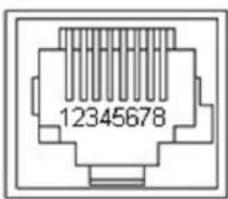
Mic Port on TRIO MIC I/O:
The Mic Port is a proprietary interface over Cat-5 cable that includes balanced audio input and output channels, and power. The RS-485 control interface is not used on the TRIO MIC I/O.
| Pin # | Mic Port (Proprietary) |
| 1 | Audio Output + |
| 2 | Audio Output - |
| 3 | Audio Input - |
| 4 | +18 VDC |
| 5 | RS-485 Control + (Not Used) |
| 6 | Audio Input+ |
| 7 | RS-485 Control – (Not Used) |
| 8 | Ground |
vaddio
Toll Free: 800-572-2011 • Phone: 763-971-4400 • FAX: 763-971-4464
www.vaddio.com
- TABLE OF CONTENTS
- OVERVIEW:
- • TRIO Mic I/O Interface (above):
- • TRIO Table Microphone Array:
- Intended Use:
- Important Safeguards:
- Save These Instructions:
- UNPACKING
- TRIO Mic I/O
- TRIO Table Microphone
- TRIO Ceiling Microphone (White Version)
- TRIO Ceiling Microphone (Black Version)
- Bundles:
- EQUIPMENT DESCRIPTIONS AND CALL-OUTS
- TRIO MIC I/O Interface
- TRIO Table Mic Array
- TRIO Ceiling Mic Array
- 1) Strain Relief Clamp:
- 2) Array Head Drop Cable:
- 3) Feed-Through Coupler:
- 4) Array Head Connector:
- 5) Internal PCBA:
- 6) TRIO Mic Port & Cable:
- TRIO MIC I/O SYSTEM CONFIGURATION AND PROGRAMMING
- Diagram: Professional Audio Mixer Connection Diagram with TRIO Mic I/O
- STEP-BY-STEP INSTALLATION INSTRUCTIONS
- TRIO Mic I/O Installation:
- STEP 1:
- STEP 2:
- STEP 3:
- STEP 4:
- TRIO TABLE AND CEILING MIC ARRAY INSTALLATION
- Trio Table Mic
- Other General Information:
- Care and Cleaning
- Operating and Storage Conditions:
- COMPLIANCE AND CE DECLARATION OF CONFORMITY: TRIO Solutions
- FC
- • FCC Part 15 Compliance
- ICES-003 Compliance
- ICES-003, Issue 4: 2004
- Standard(s) To Which Conformity Is Declared:
- EMC Directive 2004/108/EC
- APPENDIX 1: CONNECTORS PIN OUTS
- Mic Port on TRIO MIC I/O:
Brand : Vaddio
Model : EasyUSB MicPOD I/O
Category : Desk Phone