
Quick-Connect 4 - Vacuum Cleaner Vaddio - Free user manual and instructions
Find the device manual for free Quick-Connect 4 Vaddio in PDF.


| Product Type | Video, Power and Control Wiring Center |
| Brand | Vaddio |
| Model | Quick-Connect 4 |
| Dimensions (rack mount) | 2-Space Rack Mount: 3.5" (8.89 cm) height x 4" (10.16 cm) depth |
| Weight | 2.2 lbs (1 kg) |
| Power Supply | 18 VDC, 5.5 Amp, 100W (PowerRite) |
| Number of Camera Ports | 4 (individual RS-232 control) |
| Video Outputs per Camera | S-Video (4-pin mini din) and Composite Video (BNC) |
| Control Inputs | RJ-45F and DB9F (per camera) |
| Control Outputs | RJ-45F (per camera) |
| Compatible Cameras | Vaddio WallVIEW, CeilingVIEW, EZCamera, HideAway series, and Model 100/70/50/50iR PTZ |
| Max Power for HideAway Cameras | 2 HideAway units simultaneously |
| Operating Temperature Range | 0°C to 40°C (32°F to 104°F) |
| Storage Conditions | Avoid high humidity, dust, vibration, and inclement weather |
| Care and Cleaning | Use soft dry cloth; do not disassemble; no liquids |
| Warranty | 1 year limited hardware warranty |
| Included Accessories | Quick-Connect 4 unit, 18VDC power supply, Installation and User Guide |
Frequently Asked Questions - Quick-Connect 4 Vaddio
User questions about Quick-Connect 4 Vaddio
0 question about this device. Answer the ones you know or ask your own.
Ask a new question about this device
Download the instructions for your Vacuum Cleaner in PDF format for free! Find your manual Quick-Connect 4 - Vaddio and take your electronic device back in hand. On this page are published all the documents necessary for the use of your device. Quick-Connect 4 by Vaddio.
USER MANUAL Quick-Connect 4 Vaddio
Quick-Connect™ 4 Video, Power and Control Wiring Center
Figure 1: Vaddio Quick-Connect 4 Video, Power and Control Wiring Center
Front Panel (above) and Back Panel (below) shown


INTRODUCTION
The Vaddio™ Quick-Connect 4, Video, Power and Control Wiring Center (Figure 1) simplifies Operator and Presenter camera systems using the Vaddio EZCamera™ Cabling standard. The Quick-Connect 4 can accommodate up to four separate Vaddio PTZ cameras, combining and consolidating four Vaddio Quick-Connect Boxes, four PowerRite™ power supplies and four EZCamera Control Adapters used with the EZCamera cable system.
Each camera port has an individual 18VDC supply to power a single PTZ camera. Power is provided to the camera and S-Video and Composite video are both returned to the Quick-Connect 4 on the same single Cat. 5 cable for Power/Video.
Individual control ports are supplied for camera control systems like the ProductionVIEW™ and camera control daisy chaining is accommodated through the first camera control port as well.
Control inputs are either DB-9 or RJ-45 and control outputs are RJ-45, which connect easily with all Vaddio WallVIEW™, CeilingVIEW™, EZCamera and HideAway series cameras.
INTENDED USE
Before operating the Vaddio Quick-Connect 4, please read the entire manual thoroughly. The wiring system was designed, built and tested for use indoors. Outdoor operation is not recommended, has not been tested and could damage the unit and/or create a potentially unsafe operating condition. Use only the Vaddio provided power supply.
SAVE THESE INSTRUCTIONS
The information contained in this manual will help you install and operate your Vaddio Quick-Connect 4. For reference, Vaddio keeps copies of Specifications, Installation and User Guides and most pertinent product drawings for the Vaddio product line on the website. These documents can be downloaded from www.vaddio.com free of charge.
IMPORTANT SAFEGUARDS
Read and understand all instructions before using. Do not operate the device if it has been dropped or damaged. In this case, a Vaddio technician must examine the product before operating. To reduce the risk of electric shock, do not immerse in water or other liquids and avoid extremely humid conditions.

UNPACKING
Use only the power supply provided with the Quick-Connect 4 Wiring Center. Use of any unauthorized power supplies will void any and all warranties.
Carefully remove the device and all of the parts from the packaging. Unpack and identify the following parts:
• One (1) Quick-Connect 4 Wiring Center (rack mount)
• One (1) 18VDC, 5.5Amp, 100W PowerRite Power Supply
• Installation and User Guide (341-256-1)
INSTALLATION
The Quick-Connect 4 was specifically designed for simplifying the installation of camera systems using the Vaddio Cat. 5 cabling scheme for distribution of Video (both S-Video and Composite video) and Power on the same Cat. 5 cable with Control handled on a second Cat. 5 cable which adheres to both the Sony and Canon Daisy chain wiring convention for control of multiple cameras with a single control port. Below is a list of compatible Vaddio Camera Systems using the Vaddio wiring standard.
Compatible Camera Systems
The Quick-Connect 4 is compatible with the following Vaddio cameras and Camera Systems:
• Vaddio WallVIEW 100
• Vaddio WallVIEW 70
• Vaddio WallVIEW 50i
• Vaddio CeilingVIEW 70 PTZ
• Vaddio CeilingVIEW 70 PTZ HideAway*
• Vaddio CeilingVIEW 50iR PTZ
• Vaddio WallVIEW 50i PTZ HideAway*
- EZCamera PTZ Series Camera Kit (Camera, Cat. 5 Shoe and Remote)
• Vaddio Model 100 PTZ
• Vaddio Model 70 PTZ
• Vaddio Model 50 PTZ
• Vaddio Model 50iR PTZ
Controls, Inputs and Outputs (Camera 1)
*Note: Due to the power requirements for proper operation, the Quick-Connect 4 can supply power to only two (2) of the HideAway products (CeilingVIEW 70 PTZ HideAway and WallVIEW 50i PTZ HideAway) at any given time.

Figure 2: Back Panel Connections
A) Power Input (18V, +center, 5.5A) Supports up to Four (4) PTZ Cameras
B) Video/Power Connection – Carries Power to the camera and returns S-Video and Composite Video to the Quick-Connect 4
C) S-Video Output of Camera on 4-pin mini din
D) Composite Video Output of Camera on BNC
E) Control Through Output Port to Camera (RS-232 on Cat. 5 cable)
F) Control Through Input Port from Controller (RS-232 on Cat. 5)
G) Control Through Input Port from Controller (RS-232 on DB-9)
BASIC CAMERA CONNECTION
Figure 3: Single Camera Connection

4-Camera Daisy Chain Control Example (1-Control Port)
ControlVIEW Xtreme & Quick-Connect 4
Figure 4: Daisy Chain Example with Single Control Port
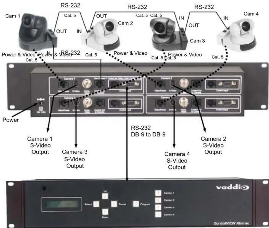
Vaddio ControlVIEW Xtreme
Quick-Connect 4
vaddio
4-Camera
Direct Control Example
(4-Control Ports)
ProductionVIEW &
Quick-Connect 4

Vaddio
ProductionVIEW FX
(6 discrete control ports -
no daisy chain control)
4-Camera
Quick-Connect 4 Head End Daisy Chain Example (1-Control Port)
Note: Cat. 5 Cable
Maximum Length for
this Control
Configuration:
50'/15.24m

Figure 6: Head End Daisy Chain Example (see Figure 7 for I/O detail)
4-Camera Quick-Connect 4 Head End Daisy Chain Example Detail
Note: Cat. 5 Cable Maximum Length for this Control Configuration: 50'/15.24m
Figure 7: Connection Detail for Head End Daisy Chain using the Quick-Connect 4

flowchart
graph TD
    A["Control Source ControlVIEW Xtreme"] --> B["Camera 1 Vaddio Model 100 PTZ"]
    A --> C["Camera 2 Vaddio Model 100 PTZ"]
    A --> D["Camera 3 Vaddio Model 100 PTZ"]
    A --> E["Camera 4 Vaddio Model 100 PTZ"]
    B --> F["3-Cat.5 Homeruns"]
    C --> G["3-Cat.5 Homeruns"]
    D --> H["2-Cat.5 Homeruns"]
    F --> I["Control to Camera"]
    G --> J["Control to Camera"]
    H --> K["Control to Camera"]
    I --> L["Control Out to QC4"]
    J --> M["Control Out to QC4"]
    K --> N["Use Came in 1 Cont for Daisy Chain Configurations"]
    L --> O["Control Inputs"]
    M --> P["Control Inputs"]
    N --> Q["Camera 1 Video/Power S-Video Comp Video Control Out to Camera"]
    O --> R["Camera 2 Video/Power S-Video Comp Video Control Out to Camera"]
    P --> S["Camera 3 Video/Power S-Video Comp Video Control Out to Camera"]
    Q --> T["Camera 4 Video/Power S-Video Comp Video Control Out to Camera"]
    R --> U["Camera 4 Video/Power S-Video Comp Video Control Out to Camera"]
    S --> V["Camera 4 Video/Power S-Video Comp Video Control Out to Camera"]
    T --> W["Camera 4 Video/Power S-Video Comp Video Control Out to Camera"]
    U --> X["Camera 4 Video/Power S-Video Comp Video Control Out to Camera"]
    V --> Y["Camera 4 Video/Power S-Video Comp Video Control Out to Camera"]
PIN-OUTS
Video/Power
The pin-outs for the Quick-Connect 4's Video, Power and Control connectors are as follows:
Video/Power Connection RJ-45
RJ-45 Pins
1) Power (+)
2) Power GND
3) Video GND
4) Y (luminance)
5) Video GND
6) C (Chrominance)
7) Video GND
8) Composite Video

Video/Power
Control Inputs
Control Input Connections RJ-45 and DB-9F

Control Inputs
RJ-45 Pins
| 1) | DTR (Sony* Daisy chain to DSR) |
| 2) | DSR (Sony* Daisy chain from DTR) |
| 3) | CTS (Canon Daisy chain to RTS) |
| 4) | RTS (Canon Daisy chain from CTS) |
| 5) | Unused |
| 6) | Digital GND |
| 7) | RXD (from TXD of control source) |
| 8) | TXD (to RXD of control source) |
*DTR/DSR also applies to Canon VCC-50i Products featuring Vaddio's exclusive VISCA Control Translation
Control Output to Camera
DB-9 Pins
| 2) Through to Pin 8 (TXD) |
| 3) Through to Pin 7 (RXD) |
| 5) Through to Pin 6 of RJ-45 |
Control Output Connection RJ-45

Control Out to Camera
RJ-45 Pins
| 1) | DSR (Sony* Daisy chain from DTR |
| 2) | DTR (Sony* Daisy chain to DSR) |
| 3) | RTS (Canon Daisy chain from CTS |
| 4) | CTS (Canon Daisy chain to RTS) |
| 5) | Unused |
| 6) | Digital GND |
| 7) | TXD (to RXD of control source) |
| 8) | RXD (from TXD of control source) |
*DTR/DSR also applies to Canon VCC-50i Products featuring Vaddio's exclusive VISCA Control Translation
CARE AND CLEANING
Do not attempt to take the Quick-Connect 4 apart. There are no user-serviceable components inside. Disassembly of the device will void the warranty.
- Do not spill liquids onto the device
- Keep this device away from food and liquid
- For smears or smudges, clear any dust with a blower and wipe stains with a clean, soft cloth. Do not use any abrasive chemicals.
OPERATING AND STORAGE CONDITIONS
Do not store or operate the Quick-Connect 4 under the following conditions for any circumstance:
• Temperatures above 40°C (104°F)
• Temperatures below 0°C (32°F)
• High humidity, condensing or wet environments
• Dusty environments
• In inclement weather
• Under severe vibration
GENERAL SPECIFICATIONS
| Camera Ports: | 4-Individual RS-232 |
| Control Through Ports: | 2-inputs on RJ-45F and DB9F per camera1-output on RJ-45F per camera |
| Power Supply: | 18 VDC, 5.5 Amp, 100W |
| Video Output Connections: | S-Video out on 4-pin mini din & Composite Video Out on BNC(Both signals are live) |
| Size: | 2-Space Rack Mount Height - 3.5" (8.89cm)4" (10.16cm) Deep |
| Weight: | 2.2 lbs, 1kg |
WARRANTY INFORMATION
Hardware* Warranty - One year limited warranty on all parts. Vaddio warrants this product against defects in materials and workmanship for a period of one year from the day of purchase if Vaddio receives notice of such defects during the warranty. They will, at its option, repair or replace products that prove to be defective.
Exclusions - The above warranty shall not apply to defects resulting from: improper or inadequate maintenance by the customer, customers applied software or interfacing, unauthorized modifications or misuse, operation outside the normal environmental specifications for the product, use of the incorrect power supply, or improper site operation and maintenance.
Vaddio Customer service – Vaddio will test, repair, or replace the product or products without charge if the unit is under warranty. If the product is out of warranty, Vaddio will test then repair the product or products. The cost of parts and labor charge will be estimated by a technician and confirmed by the customer prior to repair. All components must be returned for testing as a complete unit. Vaddio will not accept responsibility for shipment after it has left the premises.
Vaddio Technical support - Vaddio technicians will determine and discuss with the customer the criteria for repair costs and/or replacement. Vaddio Technical Support can be contacted through one of the following resources: e-mail support at support@vaddio.com or online at www.vaddio.com.
Return Material Authorization (RMA) number - Before returning a product for repair or replacement request an RMA from Vaddio's technical support. Provide a technician with a return phone number, e-mail address, shipping address, and product serial numbers. Describe the reason for repairs or returns as well as the date of purchase. Include your assigned RMA number in all correspondence with Vaddio. Write your assigned RMA number on the outside of the box when returning the product.
Voided warranty – The warranty does not apply if the original serial number has been removed or if the product has been disassembled or damaged through misuse, accident, modifications, or unauthorized repair.
Shipping and handling - Vaddio will not pay for inbound shipping transportation or insurance charges or accept any responsibility for laws and ordinances from inbound transit. Vaddio will pay for outbound shipping, transportation, and insurance charges all items under warranty but will not assume responsibility for loss and/or damage by the outbound freight carrier. If the return shipment appears damaged, retain the original boxes and packing material for inspection by the carrier. Contact your carrier immediately.
Products not under warranty - Payment arrangements are required before outbound shipment for all out of warranty products.
*Vaddio manufactures its hardware products from parts and components that are new or equivalent to new in accordance with industry standard practices.

9433 Science Center Drive, New Hope, MN 55428
Toll Free: 800-572-2011 · Phone: 763-971-4400 · FAX: 763-971-4464
www.vaddio.com
- Quick-Connect™ 4 Video, Power and Control Wiring Center
- INTRODUCTION
- INTENDED USE
- SAVE THESE INSTRUCTIONS
- IMPORTANT SAFEGUARDS
- UNPACKING
- INSTALLATION
- Compatible Camera Systems
- The Quick-Connect 4 is compatible with the following Vaddio cameras and Camera Systems:
- Controls, Inputs and Outputs (Camera 1)
- BASIC CAMERA CONNECTION
- 4-Camera Daisy Chain Control Example (1-Control Port)
- ControlVIEW Xtreme & Quick-Connect 4
- Quick-Connect 4
- vaddio
- 4-Camera
- Direct Control Example
- (4-Control Ports)
- ProductionVIEW &
- Quick-Connect 4 Head End Daisy Chain Example (1-Control Port)
- Note: Cat. 5 Cable
- Maximum Length for
- this Control
- Configuration:
- 50'/15.24m
- PIN-OUTS
- Video/Power Connection RJ-45
- Control Inputs
- Control Input Connections RJ-45 and DB-9F
- Control Output to Camera
- Control Output Connection RJ-45
- CARE AND CLEANING
- OPERATING AND STORAGE CONDITIONS
- GENERAL SPECIFICATIONS
- WARRANTY INFORMATION
Brand : Vaddio
Model : Quick-Connect 4
Category : Vacuum Cleaner