ACUP-SN000MP-CG01B - Electronic board nJoy - Free user manual and instructions
Find the device manual for free ACUP-SN000MP-CG01B nJoy in PDF.


| Product Type | Personal Vaporizer |
| Brand | nJoy |
| Model | ACUP-SN000MP-CG01B |
| Dimensions | 120 mm x 20 mm (approx.) |
| Weight | 50 g (approx.) |
| Power Source | Built-in rechargeable battery, 650 mAh |
| Charging | USB-C charging, 2 hours full charge |
| Main Functions | Heating, LED indicator, draw-activated firing |
| Cleaning | Wipe with dry cloth; clean mouthpiece regularly |
| Maintenance | Replace coil/pod as needed; keep contacts clean |
| Safety Precautions | Do not expose to water; keep away from children; use only with recommended e-liquids |
| Spare Parts | Coils, pods, mouthpieces available separately |
| Warranty | Limited 1-year warranty |
| General Information | Designed for e-liquid vaping; automatic shut-off after 10 seconds |
Frequently Asked Questions - ACUP-SN000MP-CG01B nJoy
User questions about ACUP-SN000MP-CG01B nJoy
0 question about this device. Answer the ones you know or ask your own.
Ask a new question about this device
Download the instructions for your Electronic board in PDF format for free! Find your manual ACUP-SN000MP-CG01B - nJoy and take your electronic device back in hand. On this page are published all the documents necessary for the use of your device. ACUP-SN000MP-CG01B by nJoy.
USER MANUAL ACUP-SN000MP-CG01B nJoy
natural_image
Close-up of a green circuit board with network ports and components, labeled 'Universal', 'Link', and 'PMCARD-L' (no readable text beyond labels)
Table of contents
EN
- Package contents .... 3
- Product overview .... 4
2-1. Front Panel 4
2-2. LED Status Indicators 4 - Installation 5
- Web Interface 8
4-1. Login User Account 8
4-2. Reset to Factory Default Setting / Recover from a Lost Password ..... 9 - Troubleshooting 10
Thank you for purchasing our products!
Please read this manual before using the product.

Focusing on quality at competitive prices, nJoy designs consumer products for a better and enjoyable way into the digital world.
This UPS will protect your electronic equipment from physical damage and will provide emergency battery backup power to prevent data loss in the event of power problems.
nJoy UPS models that are compatible with this product:
Aster Series
1K / 2K / 3K
Argus Series
1.2K / 2.2K / 3K
Echo Pro Series
1K / 2K / 3K
Package contents1
√ PM card
√ Spare jumper
√ User Manual
NOTE!
If any of the above package content is missing or is damaged please contact the shop where you have bought the product from.
Product overview2
2-1. Front Panel
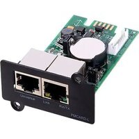
PMCARD

- Universal port
- Ethernet Port
- Tx/Rx Indicator
- Link Indicator
2-2. LED Status Indicators
| Link LED Condition | |
| Off The Power Management Card is not connected to the Network/ or the Power Management Card power is off | |
| On (Yellow) The | Power Management Card is connected to the Network |
| Tx/Rx LED | |
| Off The Power Management Card power is off | |
| On (Green) The | Power Management Card power is on |
| Flashing (Green) Re | Receiving/transmitting data packet Reset finished |
Installation3
Step 1. Hardware Installation
- Remove the two retaining screws from the expansion slot and remove the cover.
- Install the Power Management Card into the expansion slot.
- Insert and tighten the retaining screws.
- Connect an Ethernet cable to the Ethernet port of the Power Management Card.

NOTE!
The Power Management Card is hot-swappable, so you do not need to turn off the UPS to install it.
Step 2. Configure the IP address for the Power Management Card
Method 1: Using the Power Device Network Utility
- Install the Power Device Network Utility available for download at http://www.powermonitor.software/#PowerDeviceSoftware.
- After installation completes, run the "Power Device Network Utility".
- The main window of the Power Device Network Utility program is shown in Figure 1. The configuration tool will display all Power Management Card devices present on the local network subnet. The "Refresh" button is used to search the local network subnet again.
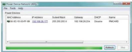
Figure 1. The main window of the "Power Device Network Utility" program.
- Select the Power Management Card you are setting up. Click on the Tools menu and select "Device Setup" or double click the device you want to configure.
- You can modify the IP Address, Subnet Mask, and Gateway address for the Device MAC Address listed in the Device Network Settings window, as shown in Figure 2. The factory default IP Address is 192.168.20.177 and the default Subnet Mask is 255.255.255.0.

Figure 2. The Device Network setting window.
-
Modify the IP, subnet mask or gateway address. Enter the new addresses into the corresponding fields and then click "Save".
-
You will need to enter a User Name and Password for the Power Management Card in the authentication window, as shown in Figure 3. Default user name: admin Default password: admin
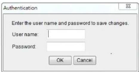
Figure 3. Authentication window.
- If the IP address change is successful, you will see a message confirming the IP set up is OK, as shown in Figure 4.

Figure 4. Setup IP Address successfully message.
- In case the change is not successful, for example, if the IP address change is unsuccessful you will see a warning message. Attempt to make the desired changes again. If the problem persists please see the Troubleshooting section for help.
Method 2: Using a command prompt
- Obtain the MAC address from the label on the Power Management Card. Each Management Card has a unique MAC address.
NOTE!
The MAC address is labelled on the card.
- Use the ARP command to set the IP address.
Example:
To assign the IP Address 192.168.10.134 for the Power Management Card, which has a MAC address of 00-0C-15-00-FF-99 you will type in the following in the command prompt from a PC connected to the same network as the Power Management Card.
(1) Type in "arp -s 192.168.10.134 00-0C-15-00-FF-99" for Windows OS; type in "arp -s 192.168.10.134 00:0c:15:00:ff:99" for Mac OS, then press Enter.
- Use the Ping command to assign a size of 123 bytes to the IP.
(1) Type in "ping 192.168.10.134 -I 123" then press Enter.
(2) If the replies are received, your computer can communicate with the IP address.
To select an available IP address for the Power Management Card, please refer to Appendix 1.
Web Interface4
4-1. Login User Account
You will need to enter a User Name and Password to login to the interface. There are two user account types.
- Administrator
Default user name: admin Default password: admin
- View only
Default username: device Default password: device
You will be asked to reset a username and password upon the first login. The administrator can access all functions, including enable/disable the view only account. The viewer can access read only features but cannot change any settings.
NOTE!
- The Administrator account is also used for the FTP login and Power Device Network Utility.
- Only one user can log in and access the device at a time.
4-2. Reset to Factory Default Setting / Recover from a Lost Password
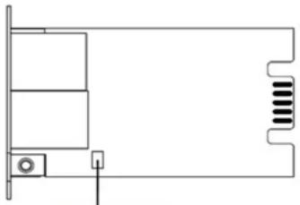
To reset the Power Management Card to its factory default setting (including web log-in user name and password), please following these steps:
natural_image
Pure technical line drawing of a mechanical or electrical component without any text, numbers, or symbolsRESET JUMPER
PMCARD
- Remove the card from the UPS without turning the UPS off.
- Remove the jumper from the reset pins as illustrated. Do not dispose of the jumper.
- Insert the card into the expansion port on the UPS.
- Wait until the green Tx/Rx LED is flashing (the frequency of the ON/OFF flashing is once per second).
- Remove the card again.
- Place the jumper back onto the Reset pins.
- Install card into the expansion port again and tighten the retaining screws.
Troubleshooting5
Problem Solution
| Unable to configure the Power Management Card using method 1 or method 2 | 1. Check the LED status, it is normal when the yellow and green LEDs are both on.If green LED is off:Check if the Power Management Card is properly seated in the device and the device has power.If yellow LED is off:Ensure the network connection is good.2. Ensure the PC being used is on the same local network subnet as the device you are trying to communicate with.3. Ensure the Jumper on the Reset Pin is correctly installed. |
| Unable to ping the Power Manage-ment Card | 1. Use method 1 and/or method 2 to get/set a correct IP address for the Power Management Card.2. If the PC being used is on a different network subnet from the Power Management Card, verify the setting of subnet mask and the IP address of gateway. |
| Lost the user name and password | Please refer to the “Reset to Factory Default Setting / Recover from a Lost Password” section. |
| Default Network Setting | IP: 192.168.20.177Subnet mask: 255.255.255.0 DHCP: On |
| Unable to access the Web Interface | 1. Ensure you can ping the PMCARD.2. Ensure you are specifying the correct URL. |
| Unable to operate a SNMP get/set | SNMPv1: Verify the community name.SNMPv3: Verify the user profile configuration. |
| Unable to receive traps | 1. Ensure the trap types (SNMPv1/SNMPv3) and trap receiver are configured correctly.2. Ensure the IP address of gateway is configured correctly if the PMCARD and NMS are on a different network. |

Disposal of Old Electrical & Electronic Equipment
(Applicable in the European Union and other European countries with separate collection systems)
This symbol on the product or on its packaging indicates that this product shall not be treated as household waste.
Instead it shall be handed over to the applicable collection point for the recycling of electrical and electronic equipment.
By ensuring this product is disposed of correctly, you will help prevent potential negative consequences for the environment and human health, which could otherwise be caused by inappropriate waste handling of this product.
The recycling of materials will help to conserve natural resources.

natural_image
Abstract orange logo design with curved shapes (no text or symbols)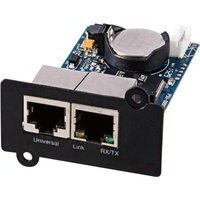


- Table of contents
- EN
- Thank you for purchasing our products!
- Package contents1
- NOTE!
- Product overview2
- 2-1. Front Panel
- PMCARD
- 2-2. LED Status Indicators
- Installation3
- Step 1. Hardware Installation
- Step 2. Configure the IP address for the Power Management Card
- Method 1: Using the Power Device Network Utility
- Method 2: Using a command prompt
- Web Interface4
- 4-1. Login User Account
- 4-2. Reset to Factory Default Setting / Recover from a Lost Password
- Troubleshooting5
- Disposal of Old Electrical & Electronic Equipment
Brand : nJoy
Model : ACUP-SN000MP-CG01B
Category : Electronic board