
ACUP-SN000MP-AZ01B - Network card nJoy - Free user manual and instructions
Find the device manual for free ACUP-SN000MP-AZ01B nJoy in PDF.


| Product Type | Electronic Acupressure Device |
| Model | ACUP-SN000MP-AZ01B |
| Brand | nJoy |
| Dimensions | 150 x 80 x 25 mm |
| Weight | 120 g |
| Power Supply | 2 x AAA batteries (not included) |
| Main Functions | Electrode stimulation, 5 modes, adjustable intensity |
| Treatment Programs | Acupressure, massage, relaxation, deep tissue |
| Timer | Automatic shut-off after 20 minutes |
| Electrodes | Reusable self-adhesive pads (pair included) |
| Display | LED indicator lights |
| Material | ABS plastic, silicone pads |
| Cleaning and Maintenance | Clean with a soft, dry cloth. Do not immerse in water. |
| Safety Features | Overheat protection, automatic shut-off |
| Accessories | 2 electrode pads, 2 AAA batteries (not included), user manual |
| Warranty | 1 year limited warranty |
| Certificate | CE, FCC, RoHS |
Frequently Asked Questions - ACUP-SN000MP-AZ01B nJoy
User questions about ACUP-SN000MP-AZ01B nJoy
0 question about this device. Answer the ones you know or ask your own.
Ask a new question about this device
Download the instructions for your Network card in PDF format for free! Find your manual ACUP-SN000MP-AZ01B - nJoy and take your electronic device back in hand. On this page are published all the documents necessary for the use of your device. ACUP-SN000MP-AZ01B by nJoy.
USER MANUAL ACUP-SN000MP-AZ01B nJoy
2.1 Features 4
2.2 Overlook 4
2.3 Installation and Connection .... 5
2.4 Configuration 6
2.5 Monitoring 7
- SNMP web pro GUI 9
- Function Menu 10
4.1 Information 10
4.1.1 Status 10
4.1.2 Basic information 10
4.2 UPS setting 11
4.2.1 Parameters setting....11
4.3 Control 13
4.3.1 Real-time control 13
4.4 System configuration 13
4.4.1 Web user 13
4.4.2 E-mail 14
4.4.3 SMS 15
4.4.4 Wake on LAN 16
4.4.5 Shutdown 17
4.4.6 Event action 17
4.4.7 Scheduled 19
4.4.8 System time 20
4.4.9 SNMP configuration 20
4.5.Log....22
4.5.1 Event log 22
4.5.2 Data Log 23
4.6. Help 24
4.6.1 Serial Port Debug 24
Thank you for purchasing our products!
Please read this manual before using the product.

Focusing on quality at competitive prices, nJoy designs consumer products for a better and enjoyable way into the digital world.
This UPS will protect your electronic equipment from physical damage and will provide emergency battery backup power to prevent data loss in the event of power problems.
nJoy UPS models that are compatible with this product:
Aten Pro Series
1K / 2K / 3K
Balder Series
1K / 1.5K / 2K / 3K / 6K / 10K
Garun Series
10KL / 15KL / 20KL / 30KL / 40KL / 60KL / 80KL
Package contents1
√ SNMP Card
√ User Manual
NOTE!
If any of the above package content is missing or is damaged please contact the shop where you have bought the product from.
Product overview2
2.1 Features
- Open monitor via Web Browser.
- Offer SNMP MIB to monitor UPS status.
• Automatically detect and exchange 10M/100M Fast Ethernet.
• Support wake-on-LAN function. - Supported protocol such as TCP/IP, UDP, SNMP, SMTP, SNTP, HTTP, HTTPS, SSL, SSH, IPV4/IPV6, DHCP and so on.
- Integrated with Shutdown Wizard, it can prevent data loss from power outage and safely shut down systems.
- Able to store event log more than 200,000 threads, including UPS warnings, faults and EMD warnings, operation data logs from web users or ViewPower pro users. It will be stored safely without loss even when power failure occurs.
• Support daily reports for event log and data log. - Scheduled UPS on/off and battery test.
• Support EMD monitoring and SMS sending. - Equipped with real-time clock to record log with date and keep running up to 7 days without power connected.
2.2 Overlook

- Ethernet port (10/100Base-T)
② Sensor port/data transmission port
③ Golden finger: connects to UPS slot
④ Ethernet port status LEDs
5 Jumper setting to restore default setting
Ethernet port status LEDs:
| 100M LED (Green) On Port is operating at 100Mbit/s | |
| Off Current web bandwidth is 10Mbit/s | |
| Link status LED (Yellow) | Flash Link Active |
| Off Card is not connected to the network | |
Pin assignment for Jumper:
| Pin # Status Description | ||
| Pin 1 & Pin 2 Closed Normal operation | ||
| Pin 2 & Pin 3 Closed After re-connecting utility, the IP address of SNMP web card and password will restore to default setting.Default static IP address: (192.168.102.230)Default password: 12345678 | ||
NOTICE!
After setting is restored to default, be sure to change the jumper setting to connect Pin 1 and Pin 2 for normal operation.
2.3 Installation and Connection
Installation
If using SNMP web card, please follow below steps to install card first:
Step 1: Remove the cover of intelligent slot on the back panel of UPS and retain the screws
Step 2: Slide the card into the open slot and secure with the screws from step 1. (see chart 2-1)

natural_image
Four-panel image showing front, top, side, and side views of a server rack unit (no visible text or labels)Chart 2-1
Refer to chart 2-2 for connecting the SNMP web pro.
Step 3: Plug Ethernet cable to the Ethernet port (RJ-45) on the SNMP web manager.
Step 4: Use one more Ethernet cable. Connect one end to the sensor port on the SNMP web manager and the other end to the optional environmental monitoring device.

flowchart
graph TD
    A["Connects to Environmental Monitoring Device"] -->|LAN| B["Router"]
    C["Client 1"] -->|LAN| B
    D["Client 2"] -->|WWW| B
    B --> E["SNMP Web Pro"]
    B -->|WAN| E
Chart 2-2
2.4 Configuration
- Please install SNMP web manager wizard in your PC. After software is installed successfully, the Installer will leave a shortcut icon on your desktop.

Chart 2-4
- Enter specific IP address to search all SNMP devices in LAN. The SNMP web manager is default applied static IP address as 192.168.102.230, default subnet mask as 255.255.255.0, and default gateway as 192.168.102.254. Users can modify IP address or apply DHCP mode through web server of SNMP web pro card, SSH Client or SNMP Web Manager.

Chart 2-5
- User can modify IP setting, online upgrade, password management, and static trap address setting in SNMP Web Manager screen. It is necessary to enter password for any medications. The default password is 12345678.
Please check SNMP Web Manager User Manual for detailed configuration.
2.5 Monitoring
There are two ways to monitor:
- Double click the selected device from the device list (refer to Chart 2-5) to open web page as Chart 2-6 a. Or simply enter https address (http://192.168.107.234) in web browser to access web server directly. Refer to Chart 2-6 b.

Chart 2-6 a

Chart 2-6 b
- Installed ViewPower Pro software to monitor SNMP web pro. Refer to Chart 2-7.
Please check ViewPower Pro User Manual for detailed monitoring.

Chart 2-7
SNMP web pro GUI3
SNMP web pro GUI includes function menu, login section and main screen. Refer to Chart 3-1:

Chart 3-1
A. SNMP web pro GUI version
B. Function Menu
It offers complete tool-set for navigation and setting the GUI.
C. Main Screen
It will display information and/or control alternatives according to function menu selected.
D. Login section
It shows user type for current login user. The default password for administrator is "12345678".
Function Menu4
4.1 Information
4.1.1 Status
Select Information >> Status. Refer to Chart 4-1. It's shown real-time monitored UPS data including input, output, UPS, battery information and environmental information in table format.

Chart 4-1
4.1.2 Basic information
Select Information >> Basic information. It includes UPS basic information, battery information and UPS rated information. Refer to Chart 4-2.

Chart 4-2
1011
4.2 UPS setting
4.2.1 Parameters setting
Some UPS functions can be set and changed via software. Parameter setting includes backup time setting for programmable outlet (P1), battery number setting, voltage and frequency range setting for bypass mode and voltage range setting for ECO mode.
Select UPS setting >> Parameters setting. Refer to Chart 4-4.

Chart 4-4
NOTE!
Different UPSs may access different parameter setting.
- Select the functions by clicking "Enable" or "Disable" button. Change the numbers by clicking up-down arrows or modify the numbers directly in the number column.
- Click "Apply" button to save the settings. Each function setting is saved by clicking "Apply" button in each section.
- Click "Default" button to recover the default setting.
NOTE!
Any functions which are not supported by UPS will not be able to access.
- Alarm Control: If enabled, UPS alarm will be activated. Vice versa.
- Alarm at bypass mode: If enabled, UPS alarms when it's working at bypass mode. Vice versa.
-
Alarm at battery mode: If disabled, UPS will not alarm when it's working at battery mode. Vice versa.
-
Auto reboot: If enabled, UPS will auto recover when AC is recovering. Vice versa.
- Bypass when UPS is off: If enabled, AC will directly provide power to connected devices when UPS is off. Vice versa.
- Converter mode: If enabled, the UPS will operate in converter mode. Vice versa.
- ECO mode: If enabled, the UPS will operate in ECO mode when input voltage is within acceptable range. Vice versa.
- Battery open status check: If enabled, the monitored UPS will check if the battery connection is ok or not when UPS is turned on.
- Cold start: If disabled, the UPS can be turned on only when AC is normally connected to UPS. Vice versa.
- Bypass not allowed: If enabled, the UPS will not transfer to bypass mode under any conditions. If disabled, the UPS will be allowed to transfer to bypass mode according to UPS internal setting.
- Battery deep-discharge protection: If enabled, the monitored UPS shuts down in accordance with the condition of battery and load on battery mode to protect battery. Vice versa.
- Site fault detection: If enabled, the monitored UPS will beep when the input neutral and hot wires are reversed. Vice versa.
- P1 Programmable outlet control (battery mode): If enabled, when UPS is running at battery mode, it will cut off P1 outlets after backup setting time arrives. If disabled, UPS will provide continuous power to P1 outlets until the battery is running out.
- Outlet setting: Users can set limited backup time for P1 outlets when UPS is on battery mode.
- Battery numbers setting: Set battery numbers in parallel.
- Voltage and frequency range for bypass mode: Set acceptable voltage and frequency range in bypass mode
- Maximum and minimum voltage: When UPS is on bypass mode and input voltage is out of setting range, UPS will enter battery mode.
- Maximum and minimum frequency: When UPS is on bypass mode and input frequency is out of setting range, UPS will enter battery mode.
• Voltage range for ECO mode: Set acceptable voltage range for ECO mode.
4.3 Control
4.3.1 Real-time control
Select Control >> Real-time control. Refer to Chart 4-5.

Chart 4-5
You can real-time control the UPS by executing following operation:
- UPS turn On/Off: Click "On" to turn on the UPS and "Off" to turn off the UPS immediately.
- Battery Self-Test: It offers three types of battery self-test: 10-second self-test, deep discharge test, and self-defined self-test. Simply clicking "Start" button from each type. It will execute the self-test immediately.
4.4 System configuration
4.4.1 Web user
It configures the authority to access SNMP web pro. Please enter access ID and password in each column. There is no limitation to access control in default setting. It is also allowed for http and https modification. The default setting is 80 for http and 443 for https. If any modification for adding web users, deleting web users or port re-configuration, it's necessary to click "Restart Web Server" button to restart web server to activate all modifications. Refer to Chart 4-6.

Chart 4-6
4.4.2 E-mail
It's allowed to send alarm mail by SMTP server. To use this function, the e-mail service must be correctly configured. All values in this function page are default empty. This action can't be executed without the SMTP information, e-mail account and password. Besides, the sender account should be allowed for SMTP/POP3 forwarding.
Select System Configuration >> E-mail. Refer to Chart 4-7
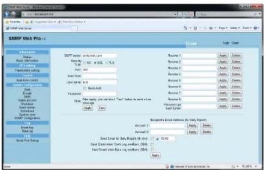
Chart 4-7
- Enter SMTP server, security type (supported encryption from SMTP server), SMTP port, sender's E-mail address, user name and password. Click checkbox of "Need Auth" for password verify.
- Enter correct e-mail accounts in Receive list. Then, click "Apply" to add into receivers list. Click "Delete" button to delete e-mail account.
- Click "Apply" to save the changes. The "Test" button can be used to send a test e-mail to all receivers to confirm correct operation. When the test e-mails are successfully sent to specific recipients, it will pop up a successful message on operated PC. Otherwise, it will pop up a failure dialog to indicate there is an error for parameter setting.
- You may decide who will receive daily report e-mail at specific duration. Please enter recipient's Email Address and timer into columns. Then, click "Apply" button to set up this action. You also can configure who will receive alarm e-mail when event log exceeds 100 or data log exceeds 50 records. Please click checkbox of selections.
4.4.3 SMS
- Sending SMS By Server
It is required to have service software available such as ViewPower Pro. In the event of an alarm condition occurring, a message about UPS status will be sent to the specified users via mobile phone. Please refer to Chart 4-8 b. - Sending SMS By Serial Port
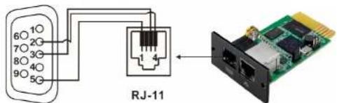
It is used EMD port as data transmission to send SMS without any service software. Please configure Baud rate of GSM Modem as 9600 and then connect data transmission port (€) of SNMP web port card to GSM Modem with a RJ11 to DB9 cable. Please refer to Chart 4-8 a for detailed wiring.
DB-9
Chart 4-8 a
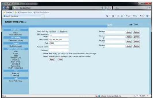
Chart 4-8 b
4.4.4 Wake on LAN
It's to remotely wake on specific PCs in LAN when these PCs are supported to Wake-on-LAN (WOL) via a magic packet.
Select System Configuration >> Wake on LAN. Refer to Chart 4-9.
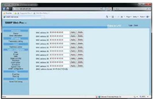
Chart 4-9
After MAC addresses of remote PCs are entered into address column, it will allow to remote control the PCs. However, it's also required to have hardware support for remote PCs to implement this function.
4.4.5 Shutdown
It is to remotely shut down specific PCs with Shutdown Wizard. This function is only available to integrate with Shutdown Wizard. Please also check user manual of Shutdown Wizard for the details.
Select System Configuration >> Shutdown. Refer to Chart 4-10.

Chart 4-10
4.4.6 Event action
This function is only available to integrate with Shutdown Wizard. Please also check user manual of Shutdown Wizard for the details.
Select System Configuration >> Event action. Refer to Chart 4-11.

Chart 4-11
- Shutdown the PC while battery mode: When selected, integrated with Shutdown Wizard, local PC will shut down while UPS works on battery mode.
- Time needed for shutting down the PC: Enter the delay time to shut down the operating system.
-
The PC should:
-
Shutdown: When clicking the checkbox, the selected system will shut down. The default setting is clicked.
-
Sleep mode: When clicking the checkbox, selected system will suspend the system instead of a normal shutdown. But this function is only supported by Windows 2000 or higher on supported hardware.
-
Also power off the UPS after shutting down the PC: When click the checkbox, monitored UPS will turn off after local system shuts down. The UPS shutdown time will be later than system complete shutdown time. Users can choose to shut down the system without shutting down the UPS.
- Shutdown UPS output after xx sec: It will cut off UPS output after monitored UPS works on battery mode for xx sec.
- Shutdown the PC while low battery: When clicking this checkbox, local PC will shut down when monitored UPS battery is running low.
- Wake on LAN while AC recovery: When clicking this checkbox, the local PC will be wake on LAN while AC recovery.
- Send E-mail while any UPS event occurs: When clicking this checkbox, it will send alarm E-mail when any event occurs on the local UPS.
- Send SMS while any UPS event occurs: When clicking this checkbox, in the event of an alarm condition occurring, a message about UPS status will be sent to the specified users via mobile phone.
- EMD alarming temperature upper limit: Set up alarm for high temperature point. If detected temperature is beyond setting value, it will send alarm message.
- EMD alarming humidity upper limit: Set up alarm for high humidity point. If detected humidity is beyond setting value, it will send alarm message.
• Data record interval xx sec: Data log record the data per xx sec.
4.4.7 Scheduled
Select System Configuration >> Scheduled. Refer to Chart 4-12.
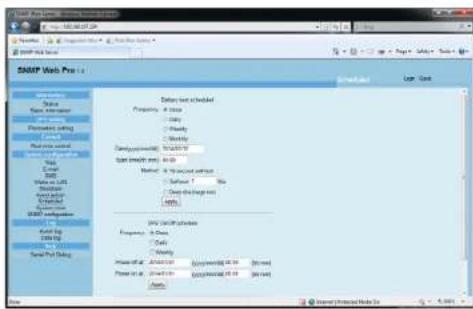
Chart 4-12
- Scheduled battery self est: Scheduled battery self est can be executed once, daily, weekly, or monthly. Users can select UPS and time parameters. It is recommended to set only one action in the same time. If multiple actions have been applied at the same time, some of these actions may be ignored. Any action will be ignored when the action is not supported by the UPS.
- Scheduled UPS on/off: Scheduled UPS on/off can be executed once, daily, weekly. Users can select UPS and time parameters. It is recommended to set only one action in the same time. If multiple actions have been applied at the same time, some of these actions may be ignored. Any action will be ignored when the action is not supported by the UPS.
4.4.8 System time
Select System Configuration >> System time. Refer to Chart 4-13.
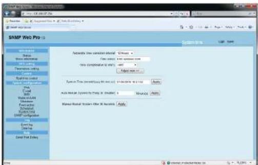
Chart 4-13
• Automatic time correction interval
• Time server: The SNTP server IP address or domain name.
• Time Zone (Relative to GMT): It's measured to relative to GMT.
- System Time (mm/dd/yyyy hh:mm:ss): It is to set up SNMP web local host time
• Auto Restart System for Every (0: Disable): XX Minute(s)
- Manual Restart system after 30 Seconds: When click "Apply" button, SNMP will restart after 30 seconds.
4.4.9 SNMP configuration
Setting SNMP web pro basic information such as IP address, password, trap IP address, SNMP UDP port, add/delete snmpv3 user account and restore the factory settings.
NOTE!
Some modifications are required to restart snmp server to become effective.
Select System Configuration >> SNMP configuration. Refer to Chart 4-14 a and 4-14 b.
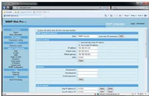
Chart 4-14 a

Chart 4-14 b
• IP address: There are two methods to obtain IP address
1. Automatically obtain IP address (DHCP, default)
2. Manually configure IP address
The system will default automatically obtain IP addresses. If there is no this kind of service provided in LAN, the default IP will display as "192.168.102.230", Net mask as "255.255.255.0" and default gateway as "0.0.0.0".
- Password: Modify the password. The length of password is 8\~15 digits.
- Trap IP address: The SNMP device could provide 12 static trap addresses.
- SNMP server configuration: You may change SNMP port and trap port. You also can add SNMPV3 users by clicking "Add" button. It will pop up a screen to set up user setting such as security level and permission level. Refer to below chart.
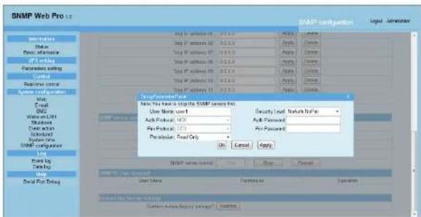
- Restore the factory settings
NOTE!
The system will default automatically obtain IP addresses and default Password is 12345678.
4.5 Log
4.5.1 Event log
In the Event Log page, it lists all history events and can be saved as .csv file. The event log includes UPS warnings, fault info, EMD warnings, UPS operation logs from web users or ViewPower pro users. All logs are recorded in flash memory of web card by month. It's safely recorded without loss even after power failure occurs. It can save up to over 200,000 threads. Refer to Chart 4-15.
Select Log >> Event log.
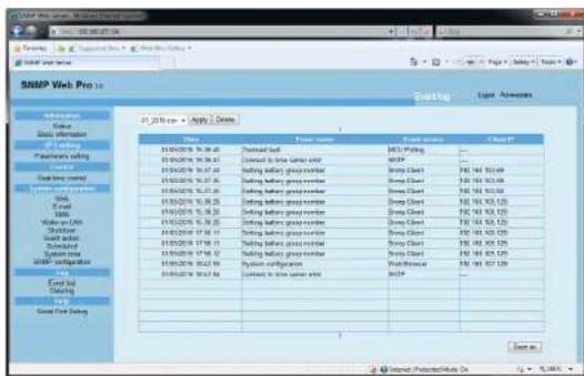
Chart 4-15
4.5.2 Data Log
In the Data Log page, it will list all history logs and can be save as .csv file. All logs are recorded in flash memory of web card by day. It's safely recorded without loss even after power failure occurs. It can save up to over 200,000 threads. Refer to Chart 4-16.
Select Log >> Data log.

Chart 4-16
4.6 Help
4.6.1 Serial Port Debug
It's to test communication condition between SNMP card and device.
Select Log >> Event log. Refer to Chart 4-17.

Chart 4-17

Disposal of Old Electrical & Electronic Equipment
(Applicable in the European Union and other European countries with separate collection systems)
This symbol on the product or on its packaging indicates that this product shall not be treated as household waste.
Instead it shall be handed over to the applicable collection point for the recycling of electrical and electronic equipment.
By ensuring this product is disposed of correctly, you will help prevent potential negative consequences for the environment and human health, which could otherwise be caused by inappropriate waste handling of this product.
The recycling of materials will help to conserve natural resources.


MemoMemo

natural_image
Abstract orange logo design with curved shapes (no text or symbols)
- Thank you for purchasing our products!
- Aten Pro Series
- Balder Series
- Garun Series
- Package contents1
- NOTE!
- Product overview2
- Features
- Overlook
- NOTICE!
- Installation and Connection
- Installation
- Configuration
- Monitoring
- SNMP web pro GUI3
- Function Menu4
- Information
- Status
- Basic information
- UPS setting
- Parameters setting
- Control
- Real-time control
- System configuration
- Web user
- SMS
- Wake on LAN
- Shutdown
- Event action
- Scheduled
- System time
- SNMP configuration
- Log
- Event log
- Data Log
- Help
- Serial Port Debug
- Disposal of Old Electrical & Electronic Equipment
- MemoMemo
Brand : nJoy
Model : ACUP-SN000MP-AZ01B
Category : Network card