HH38 - Microphone Galaxy Audio - Free user manual and instructions
Find the device manual for free HH38 Galaxy Audio in PDF.

| Product Type | Handheld Dynamic Microphone |
| Brand | Galaxy Audio |
| Model | HH38 |
| Microphone Type | Dynamic |
| Polar Pattern | Cardioid |
| Frequency Response | 50 Hz - 15 kHz |
| Sensitivity | -52 dBV/Pa |
| Impedance | 600 ohms |
| Connector Type | 3-pin XLR |
| Cable Length (Included) | 15 ft (4.6 m) XLR to XLR |
| On/Off Switch | Yes, slide switch |
| Dimensions (Length x Diameter) | 180 mm x 50 mm |
| Weight | 300 g (10.6 oz) |
| Body Material | Die-cast metal |
| Finish | Matte black |
| Included Accessories | Mic clip, carrying pouch, XLR cable |
| Primary Application | Vocals, speech, PA systems |
| Care Instructions | Clean grille with damp cloth; avoid moisture |
| Safety Warnings | Do not expose to rain or submersion |
| Spare Parts Availability | Replacement grille and capsule available |
| Warranty | 1 year limited |
Frequently Asked Questions - HH38 Galaxy Audio
User questions about HH38 Galaxy Audio
0 question about this device. Answer the ones you know or ask your own.
Ask a new question about this device
Download the instructions for your Microphone in PDF format for free! Find your manual HH38 - Galaxy Audio and take your electronic device back in hand. On this page are published all the documents necessary for the use of your device. HH38 by Galaxy Audio.
USER MANUAL HH38 Galaxy Audio
text_image
AUDIO HH52 ANY SPOT M8PS2 ANY SPOT ECMR CHANNEL 0.8 SELECT IR ABC RF AF PEAK VOLUME MIN MAX
text_image
GALAXY AUDIO®
text_image
QR code image containing encoded data, no visible human-readable textAll ECM systems include the following components:
ECMR Receiver
One 1/4" Audio Cable
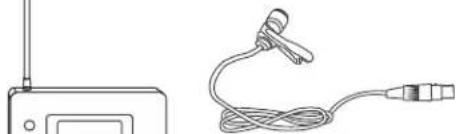
Power Adapter
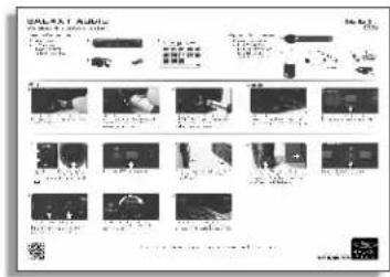
Quick Start Guide
natural_image
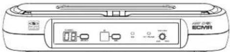
Front view of a device labeled 'ECMR' with control buttons and indicator lights (no readable text beyond label)ECMR

1/4" to 1/4"
Audio Cable

natural_image
Line drawing of a power adapter with cable and connector (no text or symbols)PS-13.5-.35.5
Power
Adaptor
text_image
Scanned document page with multiple labeled sections and accompanying images, likely a technical or legal report.Quick Start Guide
Handheld Microphone Systems:
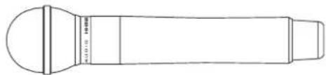
HH52 Handheld Transmitter
natural_image
Line drawing of a cylindrical device with a flanged top and side ports (no text or symbols)HH52
☐ Lavalier/Headset/Guitar Systems:
MBP52 Body Pack Transmitter
Microphone (choice of Lavalier,
Headset, or Guitar Cable)
natural_image
Line drawing of a wireless device with antenna and cable (no text or symbols)LV-U3BK

HS-U3BK

AS-GTRVE
Replacement parts can be purchased at www.galaxyaudio.com
AS-CLIP911R
Belt Clip
for MBP52

BATTCVR11005264
Battery Cover
for MBP52

WS-GR52
Mesh Grill Cover
for HH52
Front Panel

text_image
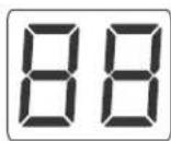
ANY 807 ECMR CHANNEL IR RF AF PEAK VOLUME SELECT ASC MIN MAX 1 2 3 4 5 6 7① Channel Display.
Displays selected Channel.
② Channel select button
③ IR Window.
Unit sends Infrared Signal to the Transmitter through this Window for Frequency Synchronization.
4 ASC Synchronizing Signal Transmit Button. Press this Button to establish Infrared connection between the Receiver and Transmitter.
⑤ RF Signal LED
6 Audio LED. Indicates a peak Audio Signal.
⑦ Audio Output Level Control.
Left turn for Output Level Decrease,
right turn for Output Level Increase.
Rear Panel

text_image
APOL INPUT XLR BALAN 350-200kV D.C.12-18V IN 400mA MUTE LEVEL 2 IN' MK UNBAL OUTPUT1
2
3
4
1 AF Audio Output.
② Power Adapter Jack.
3 AF Output fine adjustment of Mute Threshold Level.
This is factory set and usually does not need to be adjusted.
If interference signals are present, this Threshold Value can be Increased by turning the knob Clockwise until RF Signal LED goes out.
4 1/4" Audio Output.
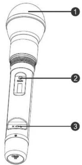
Functions:
text_image
1 2 3① Microphone Head.
② Gain (Sensitivity) Control.
Turn Left to Decrease Sensitivity.
Turn Right to Increase Sensitivity.
3 RF Power Level Switch.
H for High Level RF Power.
L for Low Level RF Power.
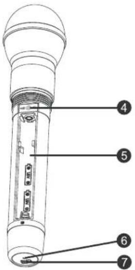
4 IR Window.
Receives Infrared signal to synchronize frequencies between Receiver and Transmitter.
⑤ Battery Tray.
6 Power/ASC/Low Battery Indicator.
Green: Power On.
Flashing Green: IR Transmission in progress.
Red: Batteries Low.
⑦ Power On/Off Switch.
Changing Batteries:
Unscrew cover to access the Battery Tray. Observe correct polarity markings when installing Batteries. Expected life for two alkaline batteries is about 8 hours.
text_image
Technical diagram of a device with numbered parts labeled 4 through 7
natural_image
Three technical diagrams of a handheld device with directional arrows indicating rotation or movement (no text or symbols present)Functions:

text_image
1 2 3 4 POWER ASG IRASC SYSTEM Auto frequency selection Auto the trigger after 5 6 ALAXY AUDIO AMY SPOT MBP62
text_image
7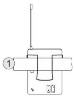
natural_image
Simple line drawing of a mechanical device with a lever and base (no text or symbols)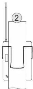
natural_image
Pure mechanical diagram showing a lever and base assembly without any text, numbers, or symbols
text_image
Open Close① Antenna.
② Input Gain Switch. There are three Gain settings. Select the setting most suitable to your application. Mic.: Microphone Level. 0: Guitar Level. -10dB: Line Level.
③ Power/Low Battery/IR Transmission LED. Green: Power On, Batteries OK. Flashing Red: Low Batteries. Flashing Green: IR transmission in Progress.
4 3-pin Input Jack.
⑤ Power Button. Press and Hold to switch Power On/Off.
⑥ ASC Automatic Frequency Synchronization. Press this button to establish Infrared connection between the Transmitter and Receiver.
⑦ IR Window. This window receives the Infrared signal during ASC.
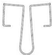
How to Wear the MBP52 Transmitter:
Slide the transmitter clip onto the belt ①, or run a guitar strap through the transmitter clip ②, as shown in the diagram at left.
Battery Replacement:
Slide open the Battery Door as shown. Install Batteries while observing correct polarity markings.
The life expectancy of two alkaline batteries is about 8 hours.
ECM Receiver Setup:
Group and Channel Selection
Press Channel UP or Channel DOWN buttons to select desired Channel. For best results when operating multiple systems, set every channel to achieve the maximum distance between channels.
Receiver Volume Control:
Turn Left for Output Level decrease, turn Right for Output Level increase.
Mute Level Threshold Adjustment:
The Mute Level is factory set and normally needs no adjustment. However, you may turn clockwise if interference is present.
Automatic Transmitter Setup (ASC):
Remove the access cover on the Handheld Transmitter. Point the IR Window of the Handheld towards the IR Window on the Receiver and press the ASC button.
Point the MBP52 Body Pack IR Window towards the Receiver IR Window, then press the ASC buttons on both the Transmitter and Receiver.
The Receiver transmits sync frequencies for 25 seconds each time you press the "ASC" button.
Whenever the ASC button on the MBP52 is pressed, the synchronizing signal will be transmitted continually for 25 seconds.
Note: When establishing infrared connection between the receiver and the transmitter, the distance between them should not exceed 1.64ft (0.5m). When more than one system are used, only IR window of one transmitter should be pointed to the receiver for each infrared connection.
ECM
Frequency
Chart
ECM
Frequency Chart

https://www.galaxyaudio.com/assets/uploads/media/MasterFrequency.pdf
| ECM D CODE | |
| 1 | 584.400 |
| 2 | 587.500 |
| 3 | 589.575 |
| 4 | 591.050 |
| 5 | 593.425 |
| 6 | 595.200 |
| 7 | 598.450 |
| 8 | 599.650 |
| 9 | 601.275 |
| 10 | 603.775 |
| 11 | 605.500 |
| 12 | 606.750 |
| 13 | 586.025 |
| 14 | 590.525 |
| 15 | 594.150 |
| 16 | 602.450 |
| ECM N CODE | |
| 1 | 518.625 |
| 2 | 519.900 |
| 3 | 520.525 |
| 4 | 521.950 |
| 5 | 523.700 |
| 6 | 524.575 |
| 7 | 526.075 |
| 8 | 531.200 |
| 9 | 531.950 |
| 10 | 534.025 |
| 11 | 535.250 |
| 12 | 537.200 |
| 13 | 538.200 |
| 14 | 539.650 |
| 15 | 540.075 |
| 16 | 541.475 |
GALAXY AUDIO
Frequency Page

http://www.galaxyaudio.com/support/schematics-and-frequency-charts
ECM System
Available Channels: 16
Frequency Range: CODE D 584\~607 MHz
CODE N 518\~542MHz
Transmitter Output level: 10 dBm
Band: UHF
Operating Range Under Typical Conditions: 200' (61m)
Note: actual range depends on RF signal absorption, reflection, and interference.
Audio Frequency Response: (+/-3dB) 60Hz\~16KHz
Total Harmonic Distortion (+/-30KHz deviation.
1KHz tone): <1%
Dynamic Range: >90dB A-weighted
Operating Temperature Range: 14°F to 122°F (-10°C to +50°C)
Note: battery characteristics may limit this range
MBP52 Bodypack Transmitter:
Audio Input Level: 0 dBV to +10dBV
Gain Adjustment Range: 20dB
Input Impedance: 5KΩ
Dimensions: 3.3" x 2.6" x 1" (85 x 65 x 24 mm) (HxWxD)
Weight: 3 oz (85 g) (without batteries)
Power Requirements: 2 AA Batteries alkaline or rechargeable batteries
Battery Life: About 8 hours
ECMR Receiver:
Audio Output Level: (+/-30KHz deviation, 1KHz tone)
XLR connector (into 600Ω load) -12dBV
1/4" connector (into 3KΩ load) -18dBV
Output Impedance: XLR connector 200Ω 1/4" connector 1KΩ
XLR output: Impedance balanced
Pin1: Ground (cable shield)
Pin2: Audio
Pin3: No Audio
Sensitivity: -93dBm for 30dB
Image Rejection: >90dB
Dimensions: 1.75" x 9.25" x 4.75" (44.45 x 235 x 121 mm)(HxWxD)
Weight: 0.85 lb (0.39 kg)
Power Requirements: 13.5 V dc at 300mA, supplied by external power supply.
HH52 Handheld Transmitter:
Max Audio input level: 0dBV
Dimensions: 9.8" x 2.1" (250 x 53 mm)(LxDia.)
Weight: 9.5 oz (270 g) (without batteries)
Power Requirements: 2 "AA" size alkaline or rechargeable batteries
Battery Life: About 8 hours
DTV Frequency Ranges & FCC Consumer Alert
Wireless Tips
Maintain line of sight between the transmitter and receiver antennas.
Do not have walls, metal objects, large crowds, etc. blocking the line of sight between the transmitter and receiver.
Antennas on the stationary equipment should be kept several feet above the ground.
Antennas can be mounted on stands or walls using brackets such as the ANT-LB.
On body pack receivers/transmitters, avoid putting them in your pocket, and/or folding the antenna under the pack. The antenna should hang freely and openly.
Keep the distance between transmitters and receivers as short as possible.
If distances above 20-30' are unavoidable, directional antennas such as the ANT-PDL can improve reception by rejecting signals outside their pickup angle.
Find out what TV stations are broadcasting in your area and avoid the channels they are on
This information is available from many sources on line, such as www.tvfool.com.
If your receiver is showing that it is receiving RF when your transmitter is turned off, you need to move to another frequency.
If you are using several systems, you can contact service@galaxyaudio.com for assistance in frequency coordination.
Make certain you are using fresh batteries, rechargeable batteries may be used, but they discharge at a much faster rate than alkaline.
The frequencies of the Galaxy UHF Wireless Systems are on frequencies that are used by Digital Television stations.
To be assured of the best performance, you should determine on what RF channels the DTV stations in your area are broadcasting, then set your wireless systems on frequencies that are not being used.
You can find that information on this FCC web site. https://www.fcc.gov/media/engineering/dtvmaps
Enter the zip code of the location where the wireless system will be used into the location search bar. A list of stations in that area will be listed. Click on the call sign of the stations and the details will appear, showing you the RF channel the TV station is using. Compare these with the chart to the left, and using the Galaxy frequency charts on page 5, find a frequency that is not on an active DTV RF channel.
For example, if you have an L-Band ECMR and your location has DTV stations on RF channels 45 and 48, you will want to set your ECMR on a frequency that is on RF channel 46 or 47.
FCC Consumer Alert for Wireless Microphones (U.S.)
Most users do not need a license to operate this wireless microphone system. Nevertheless, operating this microphone system without a license is subject to certain restrictions: the system may not cause harmful interference; it must operate at a low power level (not in excess of 50 milliwatts); and it has no protection from interference received from any other device. Purchasers should also be aware that the FCC is currently evaluating use of wireless microphone systems, and these rules are subject to change.
For more information, call the FCC at 1-888-CALL-FCC (TTY: 1-888-TELL-FCC) or visit the FCC's wireless microphone website at www.fcc.gov/cgb/wirelessmicrophones
| DTV RF Channel | Frequency Range |
| 14 | 470-476 |
| 15 | 476-482 |
| 16 | 482-488 |
| 17 | 488-494 |
| 18 | 494-500 |
| 19 | 500-506 |
| 20 | 506-512 |
| 21 | 512-518 |
| 22 | 518-524 |
| 23 | 524-530 |
| 24 | 530-536 |
| 25 | 536-542 |
| 26 | 542-548 |
| 27 | 548-554 |
| 28 | 554-560 |
| 29 | 560-566 |
| 30 | 566-572 |
| 31 | 572-578 |
| 32 | 578-584 |
| 33 | 584-590 |
| 34 | 590-596 |
| 35 | 596-602 |
| 36 | 602-608 |
| 37 | 608-614 |
| 38 | 614-620 |
| 39 | 620-626 |
| 40 | 626-632 |
| 41 | 632-638 |
| 42 | 638-644 |
| 43 | 644-650 |
| 44 | 650-656 |
| 45 | 656-662 |
| 46 | 662-668 |
| 47 | 668-674 |
| 48 | 674-680 |
| 49 | 680-686 |
| 50 | 686-692 |
| 51 | 692-698 |

text_image
GALAXY AUDIO®WARRANTY Information can be viewed online at https://www.galaxyaudio.com/support/warranty

www.galaxyaudio.com/support/warranty
ECM USER'S MANUAL
Specifications in this manual are subject to change without notice. For the most up to date manual and information visit www.galaxyaudio.com.
1-800-369-7768 www.galaxyaudio.com
© Copyright Galaxy Audio 2019