
Exterior Projection 1000 - Lighting MARTIN - Free user manual and instructions
Find the device manual for free Exterior Projection 1000 MARTIN in PDF.


| Product Type | Outdoor projection lighting fixture |
| Dimensions (HxWxD) | 771 x 417 x 702 mm (30.4 x 16.5 x 27.7 in.) with yoke |
| Weight | 50 kg (110 lbs.) including yoke |
| Power Supply | 100-277 V AC, 50/60 Hz, auto-ranging electronic switch-mode |
| Power Consumption | 645 W (120 V), 635 W (230 V/277 V) typical |
| Light Source | 440 W white light LED engine, 6500 K, CRI 72, 20,000 h lifetime |
| Color Mixing | CMY independent 0-100%, plus 7-position color wheel (dichroic filters) |
| Gobos | 7 rotating glass gobos, interchangeable, indexed or continuous rotation |
| Animation Effect | Rotating animation wheel with variable angle, speed, and direction |
| Prism | 4-facet linear and 3-facet radial rotating prisms, indexed or rotating |
| Zoom Range | Motorized 10° to 44° beam angle |
| Focus | Motorized, sharp focus from 5 m (16.4 ft.) to infinity |
| Control | DMX512 (20 channels), RDM, standalone with up to 20 scenes |
| IP Rating | IP66 (suitable for wet locations, do not immerse) |
| Safety | Class I, ground required; risk group 2 (EN 62471); hot surface up to 85 °C |
| Installation | Adjustable yoke, any orientation (sides vertical), use safety cable |
| Cleaning | Mild detergent and soft brush; avoid abrasives and high-pressure water |
| Humidity Management | Use evaporation mode and silica gel desiccant bag when closing fixture |
| Spare Parts | Silica gel bag (P/N 37220000), goboholders, gobo rings, protection spring |
| Firmware Update | Via DMX/RDM with Martin Companion software and USB-to-DMX interface |
Frequently Asked Questions - Exterior Projection 1000 MARTIN
User questions about Exterior Projection 1000 MARTIN
0 question about this device. Answer the ones you know or ask your own.
Ask a new question about this device
Download the instructions for your Lighting in PDF format for free! Find your manual Exterior Projection 1000 - MARTIN and take your electronic device back in hand. On this page are published all the documents necessary for the use of your device. Exterior Projection 1000 by MARTIN.
USER MANUAL Exterior Projection 1000 MARTIN
Exterior Projection 1000 User Manual
IMPORTANT! REMOVE TRANSPORT PROTECTION BEFORE USE!
New Exterior Projection 1000 fixtures are supplied with two cable ties fastened around internal moving parts to protect components from damage during transport. Before using the fixture, you must open the top cover and remove the cable ties. See page 8.
If an Exterior Projection 1000 fixture has been used and then correctly prepared for transport, a temporary protection spring accessory should have been installed around internal moving parts. Before using the fixture, you must open the top cover and remove the spring. See page 10.
Dimensions

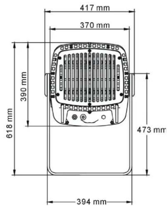

All dimensions are in millimeters
©2013-2020 HARMAN International Industries, Inc. Information subject to change without notice. HARMAN International Industries, Inc. and all affiliated companies disclaim liability for any injury, damage, direct or indirect loss, consequential or economic loss or any other loss occasioned by the use of, inability to use or reliance on the information contained in this document.
Martin, HARMAN and all other trademarks in this document pertaining to services or products by HARMAN International Industries, Inc. or its affiliates and subsidiaries are registered as the property of HARMAN International Industries, Inc.
HARMAN Professional Solutions • 8500 Balboa Blvd. • Northridge • CA 91329 • USA
Exterior Projection 1000 User Manual P/N 5088624-00 Revision H
Table of contents
Dimensions....2
Safety information....5
Introduction....8
Before using for the first time....8
Transporting the fixture....10
Fixture overview ....11
Physical installation ....12
Protection from the sun 12
Cooling 12
Protection from moisture....12
Avoiding galvanic corrosion 12
Mounting the fixture....12
Installing on a rigging truss ....13
Anchoring to a surface or structure 13
Safety cable attachment....14
Adjusting aiming (pan and tilt)....14
AC power....16
Protecting connections from moisture....16
Connecting to AC mains power....16
Control data link....18
Connecting the data link....18
Fixture setup....20
Using the control menus....20
Setting a DMX address ....20
Programming a standalone show....21
Manual control mode....21
Display settings and user password....22
Fixture status....23
Fixture configuration (including host/client operation)....23
Setting effect offsets....25
Setup via RDM 25
Effects....26
Strobe / shutter....26
Electronic dimming....26
CMY color mixing 26
Color wheel 26
Gobos....27
Animation effect....29
Prism 31
Frost 31
Focus....31
Zoom 31
Operation....32
Thermal conditions....32
Projection data 32
Service and maintenance....34
Firmware 34
Cleaning 34
Managing humidity 35
General....35
Seals and sealing surfaces 35
Pressure relief valves....35
Removing and reinstalling the top cover....36
Replacing a rotating gobo ....38
Installing a glare shield accessory 42
Remote Device Management (RDM) 43
DMX protocol....45
Control menus ....48
Warnings and error messages ....50
Troubleshooting....51
Specifications....52
Safety information

WARNING!
Read the safety precautions in this manual before installing, operating or servicing this product.
The following symbols are used to identify important safety information on the product and in this manual:
The following symbols are used to identify important safety information on the product and in this manual:

Warning! Safety hazard. Risk of severe injury or death.

Warning! Hot surface. Risk of burns.

Warning! See user manual for important safety information.

Warning! Risk of eye injury. Wear protective eyewear.

Warning! Hazardous voltage. Risk of lethal or severe electric shock.

Warning! Do not look into light output.

Warning! Fire hazard.

Warning! Risk Group 2 product according to EN 62471. Do not look directly into the beam. Do not view the light output with optical instruments or any device that may concentrate the beam.
This lighting fixture is for professional use only and must be installed by a qualified technician. It is not for household use. It presents risks of severe injury or death due to fire hazards, electric shock and falls. It produces a powerful, concentrated beam of light that can create a fire hazard or a risk of eye injury if the safety precautions below are not followed.
Respect all locally applicable laws, codes and regulations when installing, operating or servicing the fixture.
The latest software, manuals and other documentation for all Martin products are available for download at www.martin.com
The light source contained in the fixture may be replaced by Martin or an authorized Martin service agent only.
A terminal block for connection to AC mains power is not included and must be supplied by the installer.
Technical Support
If you have any questions about how to install, operate or service the fixture safely, please contact your Martin® distributor. For technical support in North America, please contact Harman Professional Technical Support by e-mail:
HProTechSupportUSA@harman.com or by phone: (844) 776-4899. For technical support outside North America, please contact your national distributor.

User documentation
Install, operate and service Martin products only as directed in their user manuals or you may create a safety hazard or cause damage that is not covered by product warranties.
Keep this user manual for future use. Before installing, using or servicing this fixture, check that you have the latest version of the user manual, available on the fixture's Tech Docs/Support page on the Martin website at http://www.martin.com. Martin user manual versions are identified by the Revision letter given at the bottom of page 2.
Refer any operation not described in this user manual to Martin Global Service or an authorized Martin service agent.
Follow the safety precautions listed below and observe all warnings in this manual and printed on the fixture. Keep this user manual for future use.

Protection from electric shock
This fixture is IP66 rated. It is suitable for use in wet locations, but do not immerse it in water or install it in a location where it may become submerged.
The fixture is a Class I product according to IEC 61140. Ensure that the fixture is electrically connected to ground (earth).
Disconnect the fixture from AC power when the fixture is not in use.
Use only a source of AC power that complies with local building and electrical codes and has both overload and ground-fault (earth-fault) protection.
The circuit used to supply the fixture with AC power must include a power switch that is easily accessible so that the fixture can easily be disconnected from power.
Shut down power to the entire installation at the main power distribution board and lock out power before carrying out any installation or maintenance work.
Isolate the fixture from power immediately if any seal, cover, cable, connector or other component is damaged, defective, deformed, wet or showing signs of overheating. Contact Martin for any service operation not described in this user manual. Do not reapply power until repairs have been completed
Before using the fixture, check that all power distribution equipment and cables are in perfect condition and rated for the electrical requirements of all connected devices.
If the external flexible cable or cord of this luminaire is damaged, it shall be exclusively replaced by the manufacturer or his service agent or a similar qualified person in order to avoid a hazard.

Protection from burns and fire
Do not operate the fixture if the ambient temperature ( Ta ) exceeds 45°C (113°F).
The surface of the fixture casing can reach up to 85° C ( 185° F) during operation. Avoid contact by persons and materials. Allow the fixture to cool for at least 10 minutes before handling.
Keep flammable materials well away from the fixture. Keep combustible materials (e.g. fabric, wood, paper) at least 0.1 m (4 ins.) away from the fixture housing.
Ensure that there is free and unobstructed airflow around the fixture.
Do not illuminate surfaces within 1.5 m (4.9 ft.) of the front glass.
Do not stick filters, masks or other materials onto any optical component.
The fixture's optical components can focus the sun's rays, creating a risk of fire and damage. Do not expose the front of the fixture to sunlight or any other intense light source.

Protection from eye injury
Do not stare directly into the light output. Ensure that persons are not looking directly into the lamp when the fixture lights up suddenly. This can happen when power is applied, when the fixture receives a DMX signal, or when certain control menu items are selected.
Do not look at the light output with magnifiers, telescopes, binoculars or similar optical instruments that may concentrate the light output.
Wear protective glasses and other PPE (personal protective equipment) when working on or near the fixture.
The risk group distances given below apply to the light output from one fixture only. If fixtures can be operated in combination, light intensity can increase and you should consult a lighting professional for safety recommendations.
The Exterior Projection 1000 is classified into the following risk groups according to EN 62471 at the distances indicated:
![graph LR A["Sun icon"] --> B["DO NOT EXPOSE"] B --> C["RISK GROUP 2"] C --> D["RISK GROUP 1"] D --> E["∞"] style A fill:#fff,stroke:#000 style B fill:#fff,stroke:#000 style C fill:#fff,stroke:#000 style D fill:#fff,stroke:#000 style E fill:#fff,stroke:#000](/content/2026/05/1063679/images/61a5a3f86f1caf83ee5e5ff8c28fe4d2e1d80fb5872c1de3c0e59218cfca5367.jpg)
At a distance of less than 0.2 m (7.9 ins.) from the fixture, the light output can potentially cause eye or skin injury before an exposed person's natural aversion responses (blink reflex and reaction to skin discomfort) can protect them. At distances greater than 0.2m (7.9 ins.), potential eye and skin injury hazards from the light output are normally prevented by natural aversion reflexes.
Position the Exterior Projection 1000 so that persons cannot be exposed to the fixture's light output at less than 0.2m (7.9 ins.) from the fixture and so that prolonged staring into the light output at less than 10 m (33 ft.) from the fixture is not expected.

Protection from injury
Fasten the fixture securely to a fixed surface or structure when in use. The fixture is not portable when installed.
Ensure that any supporting structure and/or hardware used can hold at least 10 times the weight of all the devices they support.
If suspending the fixture from a rigging truss, support it with two rigging clamps and secure it with an additional attachment such as a safety cable that will catch it if a rigging clamp fails. Check that the truss and all installation hardware are approved for the weight that they will support.
Check that all external covers and installation hardware are securely fastened.
Do not operate the fixture with missing or damaged covers, shields or any optical component.
Block access below the work area and work from a stable platform whenever installing, servicing or moving the fixture.
In the event of an operating problem, stop using the fixture immediately and disconnect it from power. Do not attempt to use a fixture that is obviously damaged.
Do not modify the fixture or install other than genuine Martin parts.
Introduction
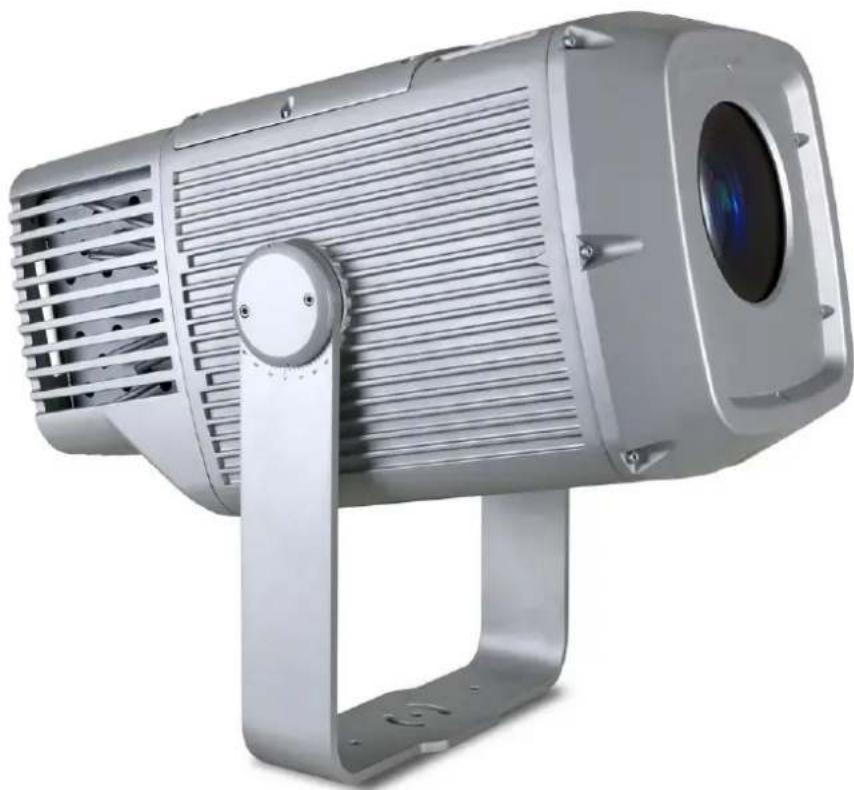
Congratulations on purchasing an Exterior Projection 1000 from Martin®. This product is a high-quality lighting fixture that combines a powerful 440 W LED engine, advanced dynamic effects and rugged weatherproofing. It gives clean, bright projections of images such as corporate logos and patterns in indoor or outdoor environments.
The fixture features a rotating gobo wheel with seven interchangeable rotating gobos and a gobo animation effect that can fill a rotating gobo projection with movement to give impressive and realistic flame or water effects, for example. The fixture has full CMY color mixing and an additional color wheel with 7 dichroic color filters. It also features one radial 3-facet and one linear 4-facet rotating prism, plus a variable frost effect. Besides these effects, the fixture features smooth electronic dimming, remote zoom and focusing and eye-catching strobe/shutter effects. It has a zoom range from 10° - 44° , allowing exact matching of the projected image to the target projection surface.
The Exterior Projection 1000 can be controlled using any controller that is compatible with the industry-standard DMX512 lighting control system. It also responds to RDM (Remote Device Management) communication if you use an RDM-compliant controller. RDM lets you set up fixtures (give DMX addresses to fixtures, for example) and retrieve status information from fixtures over the DMX data link.
The Exterior Projection 1000 can also function without DMX control as a standalone projector and run a show with up to twenty dynamic lighting effects that you can pre-program.
This user manual covers fixture software version 1.7.0.
Before using for the first time
IMPORTANT! The Exterior Projection 1000 is supplied with two cable ties fastened around internal moving parts to protect components from damage during transport. Before using the fixture, you must open the top cover and remove the cable ties!
Open the fixture in dry weather conditions only.
Before you use the Exterior Projection 1000 for the first time:
- Unpack and ensure that there is no transportation damage before using the fixture. Do not attempt to operate a damaged fixture.
- Check the fixture's Tech Docs / Product Support page on the Martin website at www.martin.com and make sure that you have read the latest user documentation and technical information about the fixture. Martin user manual revisions are identified by the revision letter at the bottom of the inside cover.
- Read 'Safety information' starting on page 5 of this user manual.
- Ensure that the voltage and frequency of the power supply match the power requirements of the fixture.
-
Follow the instructions for removing the fixture's top cover in 'Removing and reinstalling the top cover' on page 36. Lift the top cover off the fixture. For ease of access – and if it is safe to do so – you can unclip the safety cable and remove the cover completely from the fixture.
-
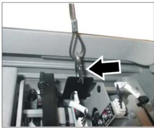
See illustration on right. Avoid dropping cable ties or other items into the fixture. Using scissors or cutting pliers, cut and remove the two cable ties (arrowed).

-
See illustration on right. If you unclipped the top cover safety cable, reattach it so that it will catch the top cover and prevent it from falling.
-
If the fixture will not be opened again before it is used, follow the correct procedure for reducing humidity when closing it: follow the instructions in 'Removing and reinstalling the top cover' on page 36.
- If the fixture will be opened again before it is used, there is no need to follow the procedure for reducing humidity and you can simply go to the next step below.
-
Put the top cover back into position on the fixture and reinstall the eight top cover screws by first inserting them finger-tight. Then use a torque driver and cross-tighten the screws in a diagonal pattern, increasing torque gradually in stages until you reach a torque of 1.9 – 3.5 Nm.
-
See illustration on right. Remove the cover (arrowed) from the control panel and display on the side of the fixture so that you can set up the fixture using the control panel.
-
If the temperature is below -20° C ( -4° F), apply power to the fixture but do not use it for 30 minutes. This will give the fixture time to warm up to within its operating temperature range.
Whenever AC power is applied to the fixture, it will reset all effects and functions to their home positions. Reset is available when fixture temperature is above -20° C ( -4° F).
After the reset, the fixture will be ready for DMX control or standalone operation.

Transporting the fixture
Important! If you need to transport the fixture after you have removed the temporary cable ties that new fixtures are supplied with to protect them during delivery (see point 6. in the previous section), you must open the top cover and install a temporary protection spring inside the fixture. Installing the spring locks the frost car at the back of its movement range so that components are protected from damage caused by movement during transport.
A transport protection spring is supplied with each fixture but you can also obtain the spring as an accessory for the Exterior Projection 1000 by ordering P/N 91611097 from your Martin supplier.
To install the transport protection spring:
- Open the top cover as described in 'Removing and reinstalling the top cover' on page 36.
- See illustrations below. Pull the frost car back as far as it will go from the front of the fixture by pulling on the metal frame of the car with your finger. Then hook the short end of the transport protection spring through the circular hole (arrowed) in the metal frame of the frost car.


- See illustrations below. Using a pair of flat-nosed pliers, hook the long end of the spring around the turret nut (arrowed) on the effects module. Check that the transport protection spring holds the frost car securely at the rear limit of the frost car's travel.


- Finally, reinstall the top cover as described in 'Removing and reinstalling the top cover' on page 36.
Important! Before using the fixture after transport, you must open the top cover and remove the spring. Leave a message on the fixture for the person who will unpack or install it, warning them that they must remove the spring before the fixture is used.
Fixture overview


- Control panel display (shown with cover removed)
- Control buttons:
| MENU | Activate the menu mode functions, orReturn to the previous level of the menu structure, orPress and hold to exit the menus |
| DOWN (▼) | Go down a menu branch |
| UP (▲) Go up a menu branch | |
| ENTER Confirm the selected function | |
- Adjustable mounting yoke
- DMX data combined in/out cable
- AC mains power cable
- Pressure relief valve
- Safety cable attachment point
Physical installation

Read 'Safety information' on page 5 before installing the fixture.
Protection from the sun
Important! The fixture's optical system can focus rays from the sun inside the fixture, causing internal damage and presenting a fire hazard. Make sure that the sun will not shine into the front of the fixture at any time.
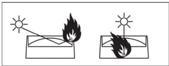
The Glare Shield available from Martin can help protect the front of the fixture from the sun. See page 42 for more details.
If the control panel will be exposed to sunlight, install its cover to protect the panel and display from heat and UV radiation.
Cooling
The Exterior Projection 1000 has a thermal protection system. If temperatures inside the fixture exceed safe levels, it regulates LED output to protect components.
The fixture has internal forced air cooling but it needs to dissipate heat externally by convention. Ensure sufficient ventilation and free airflow around the fixture, especially around the grills on the back of the fixture, to minimize any reduction in LED output in high ambient temperatures.
Protection from moisture
If there is a break or cut at any point in a cable (for example at a connection point), and if this is exposed to water, moisture can be drawn up the inside of the cable due to the vacuum effect of temperature fluctuations during operation. Ensure that the fixture is protected from the entry of water via cables by using IP66-rated connectors or junction boxes, or by protecting connectors with weatherproof housings. Make sure that all cables open into dry areas.
See illustration on right. Create a drip loop before cable glands to reduce any tendency for glands to be constantly immersed in water.

Avoiding galvanic corrosion
The fixture and mounting bracket are manufactured in corrosion-resistant anodized aluminum. Avoid mounting the fixture in direct contact with other types of metal, as this can cause galvanic corrosion. When fastening to a metal that is not aluminum:
- Use an electrically insulating material (such as rubber or plastic) or coating between the mounting bracket and the other metal.
- Use a non-conductive coating on fasteners (screws, bolts, washers, etc.) where they come into contact with the mounting bracket.
Mounting the fixture
The fixture can be mounted at any angle and the yoke can be fastened to a vertical, horizontal or angled surface, but the sides of the fixture must be vertical when installed (see examples below),
or the fixture's cooling airflow will be affected, leading to excessively high fixture temperature and reduced light output.

Do not stand the fixture freely on a surface or leave it where it can be moved or fall over. Ensure that the installation surface or structure and all fasteners used can safely bear at least 10 times the weight of all the fixtures and equipment they will support.
Installing on a rigging truss
It is possible to install the fixture temporarily on a rigging truss or similar support. If you do this, fasten two approved rigging clamps to the mounting yoke with two M12 bolts minimum grade 8.8 strength fastened through holes B in the mounting yoke base (see illustration on next page) and suspend the fixture using the two clamps.
Do not suspend the fixture from only one clamp: use two approved rigging clamps. Install the fixture hanging vertically downwards only. Secure the fixture with a safety cable as described in 'Safety cable attachment' on page 14. Check that the truss and all fasteners used can support 10 times the weight of all the fixtures and equipment that they will support.
Anchoring to a surface or structure
The fixture's mounting yoke base must be securely anchored to a flat surface on a wall, pedestal, structural beam or other suitable support. The yoke allows the fixture to be manually panned and tilted for beam aiming adjustment.
To anchor the fixture to a surface:
- See Mounting yoke base illustration on next page. Fasten a 12 mm (1/2 inch) shaft diameter bolt to the surface through the center hole A in the mounting yoke.
- Fasten two bolts with 8 mm (5/16 inch) shaft diameter to the surface with one bolt passing through each of the curved slots C to anchor the fixture. This will give approximately 90° of pan adjustment.
- Adjust the fixture's pan angle (side-to-side beam aiming) as described later in this chapter. Adjusting pan is best carried out with power applied to the fixture so that the projection is visible. Once pan is correct, fasten two 12 mm (1/2 inch) shaft diameter bolts to the surface with one bolt passing through each of the holes B. Once bolts have been installed in holes B, pan adjustment is no longer possible.
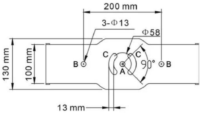
Mounting yoke base
Safety cable attachment
If a secondary attachment is required for reasons of safety (in entertainment venues, onboard marine vessels or in temporary installations, for example), you must install a safety cable:
-
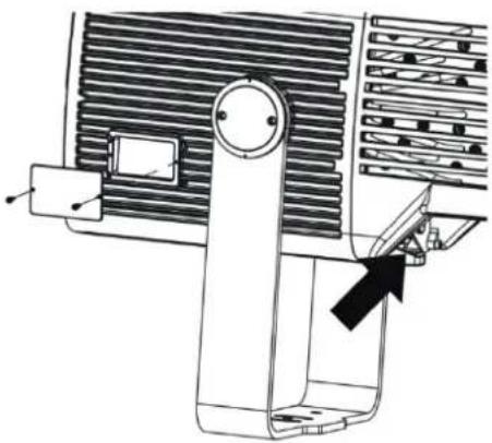
See illustration on right. Loop a safety cable that is approved for the weight of the fixture through the safety cable attachment point (arrowed) in the fixture and attach the safety cable to a secure anchoring point so that the cable will catch the fixture if the primary method of attachment fails.
-
Remove as much slack as possible from the safety cable (by looping it more than once around the anchoring point, for example). Make sure that if the primary method of attachment fails, it will be impossible for the fixture to drop any significant distance before the safety cable catches it.
Adjusting aiming (pan and tilt)

Warning! The fixture can become hot. Wear heat-resistant gloves if you adjust the aim of the fixture when it is (or has recently been) powered on.
Fixture aim adjustment is best carried out after the fixture has been connected to power and in weak light conditions so that the projection from the fixture is clearly visible.
See illustration on right. If you require very precise aiming and setup, we recommend that you order the 'Line it Up' projection setup gobo available from Martin for the Exterior Projection 1000 (see 'Accessories' on page 54) and install it in the gobo wheel while you adjust fixture aim, focus, etc.

To adjust the aim of the fixture:
-
Set the fixture to a gobo with a sharply defined pattern. You can select the image remotely either via DMX or by using the MANUAL TEST menu in the fixture's control panel.
-
Put on heat-resistant gloves.
-
See illustration on right. Loosen the tilt lock Allen (hex) screws (arrowed) on both sides of the yoke slightly, just until you can tilt the fixture in the yoke.
-
See 'Anchoring to a surface or structure' on page 13. In the base of the mounting yoke, loosen the bolts in the center hole A and curved slots C slightly, just until you can rotate the yoke.
-
Pan and tilt the fixture until it is aimed correctly.
-
Using a torque driver, tighten the four tilt lock screws to a torque of 1.8 - 3.5 Nm.
-
In the base of the mounting yoke, tighten the bolts in the center hole A and curved slots C and install bolts in holes B. Check that the fixture will be held securely in all wind and weather conditions.

AC power

Read 'Safety information' on page 5 before connecting the fixture to AC mains power. Lock out power to the entire installation before working on cables and connections.
Electrical installation must be carried out by qualified professionals only.

For protection from dangerous electric shock, the fixture must be grounded (earthed). The AC power distribution system must be fitted with current overload and ground-fault (earth-fault) circuit breakers as well as a means to isolate fixtures from power and lock out power during service.
The Exterior Projection 1000 is supplied in EU and US models. Both models accept AC power at 100-240 V nominal or 277 V nominal at 50 or 60 Hz. Do not connect to power at any other voltage or frequency.
You can connect the Exterior Projection 1000 to either of the following mains power distribution systems:
- Single-phase (live, neutral, ground/earth) system.
- Grounded/earthed three-phase four-wire (three phases, neutral, ground/earth) system.
Do not try to connect to a three-phase three-wire (three phases, ground/earth) system.
There is no power on/off switch. Power is applied to an Exterior Projection 1000 fixture as soon as it is connected to power. Provide a means to disconnect or shut down power to fixtures that is easily accessible and is located close to the fixtures.
Do not use an external dimming system to supply power to the fixture, as this may cause damage to the fixture that is not covered by the product warranty.
Protecting connections from moisture
Moisture can cause corrosion in unprotected cable connections. Moisture can also be sucked along the inside of cables at breaks or cuts in the cable jacket (for example at connection points) and into fixtures because of the vacuum effect of temperature fluctuations inside fixtures. To protect connections and fixtures from moisture, take at least one of the following precautions:
- Locate cable junctions in dry areas (e.g. junction boxes in dry locations).
- Use connectors or junction boxes that are protected to IP67 or higher.
- Fill junction boxes with potting compound to seal the ends of cables and to protect connections from corrosion.
Connecting to AC mains power
The fixture is supplied with a power cable installed ready for connection. See illustration below:

AC power cable
To connect to a single-phase system or to one phase of a three-phase four-wire system:
-
Lock out power to the installation.
-
Connect the conductors in the power cable to the distribution circuit as follows:
a) Connect the green wire (US models) or yellow/green wire (EU models) to ground (earth).
b) Connect the white wire (US models) or blue wire (EU models) to neutral.
c) Connect the black wire (US models) or brown wire (EU models) to live (one phase of a three-phase system).
- Check that all installation work is completed and carry out appropriate tests and safety checks before applying power.
Installing a temporary power plug
It is possible to install a power plug (cord cap) on the power cable for temporary use only. If you need to do this, install a grounding type (earthed) plug with integral cable grip that is rated minimum 277 V, 6 A. Follow the plug manufacturer's instructions and connect the wires in the power cable as shown in the table below:
Live or L Neutral or N
Earth, Ground or

| US system | Black White Green | ||
| EU system | Brown | Blue | Yellow/green |
Control data link
A DMX512 data link is required in order to control the fixture via DMX (and manage fixtures via RDM, if used). Your Martin supplier will be happy to help if you need advice or assistance in planning the link.
Follow these guidelines when creating a DMX data link:
- Use RS-485 data cable designed for exterior use. RS-485 cable has low capacitance and a characteristic impedance of 85 to 150 Ohms. It is electrically shielded and has at least one twisted pair of conductors. The minimum recommended wire size is 0.25 mm 2 (24 AWG) for runs up to 300 meters (1000 ft.) and 0.32 mm 2 (22 AWG) for runs up 500 meters (1640 ft.). A cable run of more than 500 meters requires the use of a splitter-amplifier to boost the DMX signal.
- If independent control of a fixture is required, that fixture must have its own DMX channels. Any fixtures that will always be required to behave identically can have the same DMX address, which means that they will use the same DMX channels.
- 512 DMX channels are available in a single DMX universe. Each time the number of DMX channels required by the fixtures on a data link reaches 512 and you want to add more fixtures, create a new DMX universe on a new data link and connect the additional fixtures to the new link.
- You can connect up to 32 fixtures in a single daisy chain on a DMX data link. Connecting in a daisy chain means that you must connect the DMX data OUT from one fixture to the DMX data IN of the next fixture, creating a single line of fixtures. Do not split the link into branches by creating a Y shape in the cable or at connectors.
- However, you can split a DMX data link into two or more branches if you use an optically isolated DMX splitter-amplifier. To preserve RDM functionality, use an RDM-compatible splitter such as the Martin RDM 5.5 Splitter. Each branch can contain up to 32 fixtures.
- If you reach the limit of 32 fixtures on a DMX data link, you can connect up to 32 additional fixtures if you add a splitter-amplifier such as the Martin RDM 5.5 Splitter to the link in order to boost the data signal. Adding a splitter-amplifier also lets you extend a data link beyond 500 meters (1640 ft.).
- The data link (and each branch of the link if you have created branches with a splitter-amplifier) must be terminated at the end by placing a 120 ohm resistor (available from Martin, P/N 04150308) across the data output hot (+) and data output cold (-) conductors of the last fixture on the link.
- Do not create long parallel runs of AC power and data cables, as these may cause interference on the data link. Even if not required by law, use separate conduits for power and data cables.
- The Exterior Projection 1000's combined data input/output cable does not support the optional second data wire pair that is provided for in the DMX512-A standard. Do not place devices that use the second data pair on the same DMX data link as Exterior Projection 1000 fixtures.
Connecting the data link
Important! Protect all connections and all breaks in cable jackets from moisture (see 'Protecting connections from moisture' on page 16).
Important! Connect the data output from one fixture to the data input of one fixture only. If you connect one data output to more than one data input, you will split the DMX data link into branches which will probably cause data signal integrity problems.
The Exterior Projection 1000 is supplied with a hard-wired 1.8 m (5.9 ft.) shielded cable with 2 pairs of wires for connection to a DMX data link.
The pair of wires with a green sleeve is for data input from the control device or previous device in the daisy chain. The pair of wires with a brown sleeve is for data output (throughput) to the next device in the daisy chain.

Exterior Projection 1000 DMX data cable
Connect the data cable as shown in the table below. Do not connect the shield conductor to ground (earth) or allow it to come into contact with a connector shell, as this may cause interference.
| Input wires(green sleeve) | Output wires(brown sleeve) | Shield | |||
| Wire color white | green white | brown black | |||
| Signal DMX in | + DMX in - DMX out + DMX out - common | ||||
| Male XLR pinout pin 3 pin 2 - | - | pin 1 | |||
| Female XLR pinout | - | - | pin 3 | pin 2 | pin 1 |
Data connection pinouts
Fixture setup

Read 'Safety information' on page 5 before operating the fixture.
Using the control menus
This section explains the fixture settings and utilities that are available using the control panel and display that are located on the side of the fixture.
You can find a full map of the control menus in 'Control menus' on page 31. Some settings and functions are also available via RDM.
Control menu settings are retained when the fixture is powered off.
Navigating in the control menus
To access the control menus, press the MENU button and hold for three seconds.
- To select a menu option or to confirm a selection, press the ENTER button.
- To scroll up and down the items in a menu, use the DOWN ARROW (▼) and UP ARROW (▲) buttons.
- To return to a higher level in the menu structure, press the MENU button.
- To exit all active control menus and return directly to the top level, press and hold the MENU button.
Passwords
The Exterior Projection 1000 onboard control panel is password-protected to discourage tampering. There are two passwords:
- A user password that is set to 123 by default but can be changed to any number from 0 to 999. This password is required to enter the control menus.
- A service password that is factory-set to 111 and cannot be changed. This password can be used to enter the control menus if necessary.
To enter or set a password, use the DOWN ARROW and UP ARROW buttons to scroll to the required number. When the number is displayed, press ENTER to confirm.
Setting a DMX address
The Exterior Projection 1000 uses twenty DMX channels to receive instructions from a DMX controller. The fixture's DMX address, also known as the start channel, is the first of these channels. If a fixture that requires 4 DMX channels has its DMX address set to 1, for example, then it uses channels 1, 2, 3 and 4. The next fixture can have its DMX address set to 5, the next to 9 and so on until all the 512 channels in one DMX universe are allocated.
If you want independent control of a group of fixtures, give each fixture its own DMX address so that each fixture has its own control channels. If you want a group of fixtures of the same type to always behave identically, give all the fixtures the same DMX address so that they all use the same DMX control channels.
You can set a fixture's DMX address using the fixture's control panel or by sending commands from an RDM-compliant DMX controller.
To set the fixture's DMX address from the control panel:
- Press and hold the MENU button to access the control menu.
-
Use UP and DOWN to select DMX ADDRESS from the menu. Press ENTER.
-
The fixture's current DMX address is displayed. Press UP or DOWN to scroll to the DMX address that you want to give to the fixture.
- Press ENTER to store the DMX address in the fixture.
- Press MENU to exit.
Programming a standalone show
You can program a standalone show – a sequence of 'scenes' that run in a loop – in the Exterior Projection 1000. A scene consists of a combination of effects such as gobo selection, gobo movement, color, intensity, etc. You can set the standalone show to run if you are not using a DMX controller or if a signal from a DMX controller is lost. The show can have up to 20 scenes that display for up to 10 minutes each. You can program 'fades' (changes from one scene to the next) so that scenes change immediately or change gradually over a period of up to 120 seconds' duration.
Note: To enable standalone operation, the OFFLINE MODE setting in the FIXTURE CONFIG menu must be set to RUN SHOW. See 'Offline mode – behavior when no DMX or Host signal is received' on page 24. A fixture will only run a standalone show when it is not receiving a DMX signal.
To program a stand-alone show:
- Access the control menu and use UP and DOWN to scroll to PROGRAM SHOW. Press ENTER to select.
- Set the total number of scenes:
a. Select SET SCENE TOTAL and press ENTER.
b. Use UP and DOWN to select from 1 to 20 scenes.
c. Press ENTER.
- Modify the appearance of scenes:
a. Select EDIT SCENE and press ENTER.
b. Select the scene that you want to modify and press ENTER.
c. Select the effect that you want to adjust (Strobe, Dimmer, Cyan, Magenta, Yellow, Color Selection, Gobo Selection, Gobo Ind/Rot, Animation Index, Animation Rotation, Frost, Prism, Prism Rotation, Zoom, Focus) and press ENTER.
d. Press UP or DOWN to scroll to a value. When satisfied, press ENTER to confirm your selection.
e. Repeat steps c) and d) for each effect.
f. Press MENU to go back up one level in the menus and select another scene to modify.
g. When done editing scenes, press MENU again to return to the PROGRAM SHOW menu.
- Set the length of time each scene is displayed before fading to the next scene and set the length of time one scene fades to the next scene:
a. Select SET SHOW TIMES and press ENTER.
b. Select SET HOLD TIME and press ENTER. Press UP or DOWN to scroll to scene duration from 0 to 600 seconds. Press ENTER to confirm your selection.
c. Select SET FADE TIME and press ENTER. Press UP or DOWN to scroll to a scene change fade duration from 0 to 120 seconds. Press ENTER to confirm your selection.
- Press MENU to exit.
Manual control mode
The fixture can be tested, reset and returned to default factory settings manually from the control panel. To enter manual mode:
- Access the control menu and select MANUAL MODE.
- Press ENTER.
Manual test / manual single scene display
The manual test commands let you display a single scene (i.e. a single combination of effects) manually, either for test purposes or to control the fixture without a DMX controller. To set up the scene:
- Select MANUAL TEST and press ENTER.
- Use UP and DOWN to scroll through the fixture's effect controls (Strobe, Dimmer, Cyan, Magenta, Yellow, Color Selection, Gobo Selection, Gobo Ind /Rot, Animation Index, Animation Rotation, Frost, Prism, Prism Rotation, Zoom, Focus).
- Press ENTER to select an effect to adjust.
- Use UP and DOWN to select a value for the effect, and press ENTER to confirm your selection.
- Repeat for each effect you want to control.
- Press MENU to exit.
Any scene that you set in the MANUAL TEST menu is retained in memory when fixture power is cycled off and on. The MANUAL TEST menu therefore lets you set up a permanent single-scene display without DMX control.
Resetting effects
To reset an effect, returning it to its default setting:
- Select RESET FUNCTIONS and press ENTER.
- Select ALL or one of the effects.
- Press ENTER to reset.
- Press MENU to exit.
Returning to factory defaults
To return the fixture to its factory default settings, erasing any settings, standalone scenes, etc. stored in the fixture's memory:
- Select FACTORY DEFAULT and press ENTER.
- Select YES to return to factory defaults or NO to exit.
- Press ENTER to confirm.
- Give the fixture time to return to the factory default settings.
Display settings and user password
The DISPLAY SETTING menu provides options to invert, dim, and turn off the backlit LCD control panel display. It also lets you lock and unlock the display and set a user password.
Display inverse
For easier reading when the fixture is mounted upside down, flip the display as follows:
- Select DISPLAY INVERSE and press ENTER.
- Select YES to invert the display or NO for normal reading.
- Press ENTER to confirm.
Display auto turn off
Important! We strongly recommend that you set the display to turn off automatically after 1 minute in order to maximize the lifetime of the display. AUTO OFF → YES is the factory default setting.
The display can be set to stay on or to turn off 1 minute after the last key press.
To set display behavior:
- Select DISPLAY AUTO OFF and press ENTER.
- Select NO to keep the display illuminated, or YES to have the display turn off automatically after 1 minute.
- Press ENTER to confirm.
Display intensity
To adjust the brightness of the control panel display:
- Select INTENSITY and press ENTER.
- Scroll to a value from 0 to 100%.
- Press ENTER to confirm.
Locking the display
The onboard control panel and display are unlocked by default. If you want to prevent unauthorized tampering, you can lock the control panel. If the control panel is locked, it is impossible to make any changes in the control menus until the service password 111 has been entered to unlock it.
To lock or unlock the control panel and display:
- Select LOCK DISPLAY and press ENTER.
- Select ON to lock the display or select OFF to unlock.
- Press ENTER to confirm.
Setting the user password
Besides the service password 111 which cannot be changed, the Exterior Projection 1000 also has a user password that you can change. The user password is set to 123 by default. To change the user password:
- Select SET PASSWORD and press ENTER.
- Scroll to a value from 0 to 999.
- Press ENTER to confirm.
Fixture status
You can view the following fixture status information in the FIXTURE STATUS menu:
- Current temperature of LED engine.
- Total number of hours the fixture has been in use.
- Total number of hours the LEDs have been powered on.
- Software version currently installed in the fixture.
You can also call up fixture status information from an RDM-compatible controller.
Fixture configuration (including host/client operation)
The FIXTURE CONFIG menu contains additional settings for customizing behavior.
Host/client operation – important guidelines
Fixtures operating in standalone mode can be synchronized in host/client operation if they are all connected to each other on a DMX data link.
In host/client operation, one fixture running a standalone show – the 'host' fixture – sends 'fade' and 'wait' signals to the other fixtures running standalone shows – the 'client' fixtures – so that scene change times in client fixtures are synchronized with the scene change times in the host.
Every time the host changes to its next pre-programmed scene, the client fixtures change to their next pre-programmed scene at the same time.
Note the following:
- Although scene changes in host and client fixtures all occur at the same time, scenes do not have to be identical. You can program different effects in the standalone scenes of different fixtures.
- Each fixture displays its own pre-programmed standalone show until it reaches its last scene, then it starts the show sequence again and continues in a loop. If all fixtures have the same number of scenes in their shows, they will all start shows in synch. If the standalone shows in different fixtures have different numbers of scenes, the fixtures will restart their shows at different times relative to each other.
- If no controller is connected to the first fixture on the link, you can improve the quality of the data signal sent to client fixtures by connecting a DMX termination plug (a plug with a 120 Ohm resistor across data hot and data cold) to the data input of the first fixture.
- DMX and RDM signals will override standalone operation in both the host and the client fixtures. This means that standalone operation is only possible if no DMX signal is present.
- You must set only the first fixture on the link to be the host fixture. Set all the other fixtures as clients. If you set more than one fixture to act as host, fixtures may have unexpected behavior.
Setting up host/client operation
Set up host/client operation as follows:
- Program a standalone show in each fixture as described under 'Programming a standalone show' on page 21.
- On each fixture, access the control menu and select FIXTURE CONFIG. Press ENTER.
- Check that all fixtures are set to CLIENT. On the first fixture on the link – and only on this fixture – select HOST and press ENTER. Press MENU to return to the FIXTURE CONFIG menu.
- On each fixture, scroll to OFFLINE MODE and press ENTER. Then select RUN SHOW and press ENTER. Finally, press and hold MENU to exit the control menus.
- Fixtures will now run standalone shows synchronized with the host fixture's standalone shows whenever the fixtures are powered on and not receiving a DMX control signal.
Offline mode – behavior when no DMX or Host signal is received
There are three options for setting how a fixture behaves in offline mode, i.e. when it is not receiving a control signal from either a DMX controller or a host fixture:
• RUN SHOW: Fixture executes its standalone show (fixture must be set to HOST).
- If the fixture is set to HOST and it does not receive a control signal, the fixture will execute the scenes in its pre-programmed standalone show (see 'Programming a standalone show' on page 21). It will also send a signal to any fixtures that are connected to it and set to CLIENT instructing them to run their standalone shows.
- If the fixture is set to CLIENT and it does not receive a control signal, it will black out until it receives a control signal.
- DMX LAST STATE: Fixture holds and displays the last received DMX command (fixture must be set to HOST).
- If the fixture is set to HOST and it does not receive a control signal, it will continue to obey the last DMX command that it received.
- If the fixture is set to CLIENT and it does not receive a control signal, it will black out until it receives a control signal.
- BLACK OUT (default): Fixture blacks out.
- If the fixture is set to HOST and it does not receive a control signal, it will black out until it receives a control signal.
- If the fixture is set to CLIENT, it will always black out if it does not receive a control signal.
The three options listed above also determine the fixture's behavior if the fixture is receiving a control signal but that signal is suddenly lost.
To set a fixture's offline mode behavior:
- Access the control menu and scroll to FIXTURE CONFIG. Press ENTER.
- Scroll to HOST/CLIENT and press ENTER. If you are going to set the fixture to RUN SHOW or DMX LAST STATE, scroll to HOST and press ENTER to confirm. Press MENU to go back up one level.
- Scroll to OFFLINE MODE and press ENTER. Press UP or DOWN to select RUN SHOW, DMX LAST STATE or BLACK OUT. Press ENTER to confirm.
Setting effect offsets
You should normally never need to change the Fixture Offsets setting. We recommend that you change the setting with guidance from Martin Service only.
You can adjust the home position of each effect by setting an offset in the FIXTURE OFFSET menu. Adjustments are held in memory when the fixture is powered off and on.
Offsets can be used to match multiple fixtures after they have been installed (if precise gobo alignment is required, for example).
To reduce the risk of unauthorized tampering with the fixture, you must enter the user password (factory default = 123) before you can access the FIXTURE OFFSET menu.
Setup via RDM
The Exterior Projection 1000 is compatible with RDM (Remote Device Management). Using an RDM-compliant DMX controller, you can communicate with all the fixtures on a data link without needing to access the fixture's control panels or connect to each fixture individually. RDM lets you set the DMX addresses of all the fixtures on the link, carry out basic fixture configuration and retrieve basic fixture data.
See Remote Device Management (RDM) on page 43.
Effects
Strobe / shutter
The strobe / shutter effect provides instant open and blackout as well as variable speed regular and random strobe effects.
Electronic dimming
Overall intensity can be adjusted 0-100%. 16-bit dimming resolution is available using two DMX channels.
CMY color mixing
CMY color mixing available on three DMX channels allows fine color adjustment.
Color wheel
The color wheel contains the 7 dichroic color filters listed below plus an open (white) position.
Colors can be selected in full position steps or continuously scrolled for split colors. The color wheel can be rotated with variable speed and direction. It can also be set to display random colors at slow, medium and fast speeds. The color wheel is shown below viewed from the LED side (rear of the fixture):

Color wheel
Slot 1: Deep Red
Slot 5: Qgean
Slot 2: Light Blue
Slot 6: CTB
Slot 3: Primary Green
Slot 7: Violet
Slot 4: CTO
As an alternative to the above colors, Martin can supply custom color filters made to special order. Please consult your Martin supplier for details.
Gobos
The fixture contains a rotating gobo wheel with the seven rotating glass gobos shown below installed as standard. The gobo wheel below is viewed from the front glass side (front of the fixture):
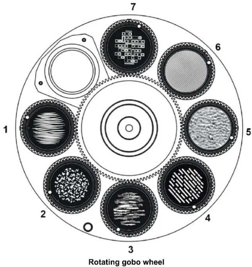
Gobo 1: Grass Lines Gobo 5: Ripple Texture Glass
Gobo 2: Organic Delight Gobo 6: Lined Effect Glass
Gobo 3: Brush It Gobo 7: Sequence It
Gobo 4: Light Lines
The gobos can be set to indexed positions and rotated continuously with variable speed and direction.
To project a gobo, select the gobo and action type (indexed angle or rotation) on channel 8, then adjust the indexed angle or direction and speed of rotation on channels 9 and 10 until you obtain the projection you want. Using two channels for adjustment gives 16-bit control.
Custom gobos
Gobos are user-replaceable. You can replace them with custom gobos made to your own design provided that the gobos meet the quality and specifications of the Martin gobos supplied with the fixture (see 'Gobos' on page 53).
If you replace one of the standard gobos with a custom gobo, we recommend that you glue a gobo ring with a key onto the gobo (see photos below). The key fits into a keyway in the goboholder and prevents the gobo from moving in the goboholder and losing its correct orientation over time.
Gobo rings can be ordered in a set of 10 as an accessory from your Martin supplier. Ask for P/N MAR-91611851.
The ring must be glued to the gobo using a silicone adhesive sealant that bonds to glass and metals and that is suitable for use in temperatures from -55° C to 200° C continuous operation. See page 38 for instructions on replacing rotating gobos.


Gobo indexing angles and precise gobo indexing
Mechanical tolerances mean that there can be small changes in the indexing angles (i.e. rotational angles) of gobos when you rotate them or change gobos and then return to the initial indexing angle.
From firmware version 1.7.0 (available early 2020), a 'Precise gobo indexing' mode is available on the fixture settings DMX channel 20. This mode returns gobos more accurately to their original position after a move. If you require the tightest possible gobo indexing angle repeatability and the fixture is running an earlier firmware version, we recommend that you update to firmware v. 1.7.0 or later and enable 'Precise gobo indexing'.
In ‘Precise gobo indexing’ mode, the fixture always moves gobos to their programmed angles from a counterclockwise direction (as seen when looking at the projection). If you enable ‘Precise gobo indexing’, you should also always move gobos to indexing angles from a counterclockwise direction while you are programming a show on a DMX controller or programming a stand-alone show as described under ‘Programming a standalone show’ on page 21. If you overshoot the desired angle, do not fix the problem by moving the gobo back to the desired angle in a clockwise direction. Instead, move the gobo back past the desired angle in a clockwise direction, then move it to the desired angle from a counterclockwise direction again.
Note that you do not need to have 'Precise gobo indexing' mode selected during programming. In fact, it might be easier to disable this mode during programming and then enable it in the final cue.
Note also that slow fading from one gobo indexing angle to another is slightly less smooth when 'Precise gobo indexing' mode is enabled. If you want to compensate for this, use short fades or snap to indexed angles, or program a blackout cue prior to the indexed position.
No matter how carefully we engineer and manufacture Martin products, all lighting fixtures are subject to mechanical tolerances. These will often cause very small changes in the indexing angles (i.e. rotational angles) of gobos if you rotate or change gobos and then you return to the initial gobo indexing angle. To reduce the visibility of any change in indexing angle, we recommend that you avoid programming very tight gobo mapping in multiple fixtures. For example, avoid aligning a vertical or horizontal line in gobo projections from two or more fixtures.
The offsets (changes in rotational angle of the gobo projection) that apply to the Exterior Projection 1000 are as follows:
• Maximum offset: 0.02 rad (1.15° or 30 mm offset at a beam diameter of 300 cm)
- Typical offset at individual gobo indexing or after fixture reset: < 0.0067 rad (less than 0.4° or 10 mm offset at a beam diameter of 300 cm)
- Typical offset at change between gobos: < 0.01 rad (less than 0.6° or 15 mm offset at a beam diameter of 300 cm
Animation effect
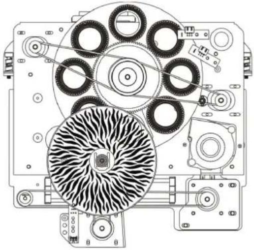
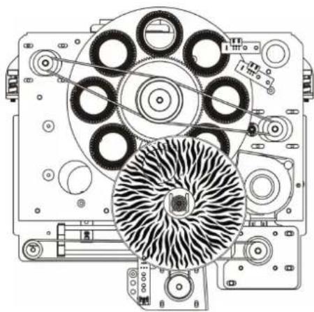
The gobo animation effect is designed to be combined with a rotating gobo and color filter to create a moving image of flames, grass blowing in the wind, water, etc.

Animation effect
Adjust the speed and direction of the gobo rotation, the speed and direction of the animation effect and fixture focus to give the most realistic animation.
You can adjust the position of the animation wheel on a separate DMX channel. This lets you modify the angle of the animation effect.
In projections where animation and prism effects are combined with CMY color mixing, color fringing will be visible around sharp edges, especially on less saturated colors. The fringing is unavoidable with this combination of effects, but it is not unattractive and it gives depth to gobos.
Animation Horizontal 45°

Animation Horizontal 90°


Animation Horizontal 135°

Animation Horizontal 156°

Prism
The fixture has one 4-facet linear rotating and one 3-facet radial rotating prism. Either prism can be deployed to obtain rotating split beam effects. Each prism can be set to an indexed position or rotated with variable speed and direction.
Frost
The frost filter softens the light output, giving a diffuse beam. You can adjust the level of diffuser applied.
Focus
The motorized focus lets you adjust the sharpness of projections from the controller. Gobo animation effects, for example, can be most effective if they are slightly out of focus.
The minimum distance at which you can obtain sharp focus is 5 m (16.4 ft.) between the fixture and projection surface.
Zoom
The motorized zoom let you adjust the beam angle from 10° - 44° .
Operation
Thermal conditions
The Exterior Projection 1000 is designed for use in ambient temperatures between -30° C ( -22° F) and 45° C ( 113° F). For instant wake-up with no warm-up mode, we recommend that you keep power applied constantly in ambient temperatures below 0° C ( 32° F).
If the fixture's temperature rises above its normal operating range, it regulates its light output in order to protect components from heat damage. As the ambient temperature nears 45°C (113°F) and if the fixture is exposed to strong sunlight, for example, output intensity will be reduced.
Projection data
When projecting a gobo with an image of maximum size at a perpendicular surface (i.e. tilt angle 0° relative to the surface), you can obtain the following image sizes and light intensity in the projection:
Narrow zoom setting (10°)
| Distance to projection surface | 10 m(33 ft.) | 20 m(65.6 ft.) | 30 m(98 ft.) | 40 m(131 ft.) | 50 m(164 ft.) |
| Projection diameter in meters (ft.) | 1.5 m(5.0 ft.) | 3.0 m(10.0 ft.) | 4.5 m(14.9 ft.) | 6.1 m(19.9 ft.) | 7.6 m(24.9 ft.) |
| Center illuminance in lux | 7310 1828 812 457 292 | ||||
| Center illuminance in candela | 679 170 75 42 27 | ||||
Projection data, gobo with maximum image size, narrow zoom (10°)
Medium zoom setting (16°)
| Distance to projection surface | 10 m(33 ft.) | 20 m(65.6 ft.) | 30 m(98 ft.) | 40 m(131 ft.) | 50 m(164 ft.) |
| Projection diameter in meters (ft.) | 2.4 m(8.0 ft.) | 4.9 m(16.0 ft.) | 7.3 m(24.0 ft.) | 9.7 m(32.0 ft.) | 12.2 m(40.0 ft.) |
| Center illuminance in lux | 3110 778 346 194 124 | ||||
| Center illuminance in candela | 289 72 32 18 12 | ||||
Projection data, gobo with maximum image size, medium zoom (16°)
Wide zoom setting (44°)
| Distance to projection surface | 10 m(33 ft.) | 20 m(65.6 ft.) | 30 m(98 ft.) | 40 m(131 ft.) | 50 m(164 ft.) |
| Projection diameter in meters (ft.) | 7.0 m(23 ft.) | 14.0 m(46.0 ft.) | 21.0 m(68.9 ft.) | 28.0 m(91.9 ft.) | 35.0 m(114.9 ft.) |
| Center illuminance in lux | 420 105 47 26 17 | ||||
| Center illuminance in candela | 39 10 4 2 2 | ||||
Projection data, gobo with maximum image size, wide zoom (44°)
Service and maintenance

Read 'Safety information' on page 5 before servicing the fixture.
Important! Opening the fixture can allow moisture to enter and cause condensation on the front glass. Read ‘Managing humidity’ below and follow the guidelines in this user manual carefully.
Refer any service or repair operation not described in this manual to an authorized Martin service technician. Do not try to carry out such an operation yourself, as doing so may present a health or safety risk. It may also cause damage or malfunction, and it may void your product warranty.
Installation, on-site service and maintenance can be provided worldwide by the Martin Global Service organization and its approved agents, giving owners access to Martin's expertise and product knowledge in a partnership that will ensure the highest level of performance throughout the product's lifetime. Please contact your Martin supplier for details.
Optical components have fragile coatings and are exposed to very high temperatures. Handle and store components with care. Wear cotton gloves while handling them. Keep them perfectly clean and free of oil and grease to reduce the risk of heat damage.
Firmware
The Exterior Projection 1000 accepts firmware (fixture software) updates via the DMX/RDM link if you use an uploader tool such as the Martin Companion application running on a Windows PC. Connect the PC to the DMX/RDM link via a suitable USB-to-DMX hardware interface such as the Martin Companion Cable, P/N 91616091. See the Martin website at www.martin.com for details of the firmware upload options available.
The information given in this user manual covers firmware version 1.7.0. If a fixture is running an earlier version of the firmware, the fixture may not behave exactly as described in this user manual. Bear in mind also that, if we release a new version of the firmware in the future, the later firmware may not contain any changes that require an update to this user manual.
The latest firmware for all Martin products, with details of changes between firmware versions, is available on the Martin website at www.martin.com. The Martin website also gives details of recommended firmware upload tools. Your Martin supplier will be glad to help if you wish to upload firmware to a Martin product and need assistance.
Cleaning
Regular cleaning is essential for fixture life and performance. Buildup of dust and dirt degrades the fixture's light output and cooling ability.
Cleaning schedules will vary greatly depending on the operating environment. It is therefore impossible to specify precise cleaning intervals for the Exterior Projection 1000. Inspect fixtures within their first few weeks of operation to see whether cleaning is necessary. Check again at frequent intervals. This procedure will allow you to assess cleaning requirements in your particular situation. If in doubt, consult your Martin dealer about a suitable maintenance schedule.
Do not use products that contain solvents, abrasives or caustic agents for cleaning, as they can cause surface damage to the fixture. The aluminum housing and front glass can be cleaned with mild detergents such as those for washing cars.
To clean the housing and front glass:
- Isolate the fixture from AC power and allow the fixture to cool for 20 minutes.
- Visually check that the silicone seals and the power and data cables are in good condition. If any seal or cable shows signs of damage, cracking or loss of water resistance, stop cleaning the fixture and contact a Martin authorized service technician for replacement.
-
If seals are in good condition, rinse off loose dirt with a hose or low-pressure water spray.
-
Wash the aluminum housing and front glass using warm water with a little mild detergent and a soft brush or sponge. Do not use abrasive cleaners.
- Rinse with clean water and wipe dry.
Managing humidity
Martin Exterior fixtures are IP66-rated and are designed to resist water and moisture in environments with widely varying climate, temperature and humidity conditions. But if fixtures are not managed correctly during installation and service, water and moisture can enter, leading to humidity and condensation inside the fixtures. Maximize the performance and service life of your product by following the precautions in this section.
General
- Carry out service during low-humidly weather conditions (or indoors if possible). Check that fixtures are dry and free of moist air before closing them.
- Tighten cover screws exactly as directed in this manual and using a torque driver.
- Make sure that all threads are clean and dry. Do not apply lubricant to threads before assembly. While lubricant may make disassembly easier during future service, it means that tightening screws to the specified torque will compress seals too much.
- Air and water can be sucked along cables and into fixtures. A cracked or porous cable jacket can allow water into the cable. Replace any cable that is not in perfect condition. Make sure that cables from fixtures open into dry areas (e.g. junction boxes in dry locations).
- Do not clean fixtures with high-pressure water jets or immerse them.
Seals and sealing surfaces
The fixture must be sealed effectively. Covers have silicone seals that will withstand rain and water splashing but will not withstand immersion or high-pressure water jets. Reinstall covers and seals carefully if you have removed them.
- Make sure that seals and sealing surfaces are perfectly clean, dry and in perfect condition before installing a cover. If you need to clean seals, use water and a soft cloth only. Replace any seal that shows signs of aging, damage, cracking, stretching or deformation. Replacement seals are available from Martin.
- Reinstall seals in exactly their original position.
- Install seals so that they closely follow the profile of the metal parts they are installed on. When you run your finger around the sealing surface after you have installed a cover, you should not be able to feel any places where the seal sticks out or sinks into the gap between the sealing surfaces.
- Do not use liquid gasket or any other type of sealant on sealing surfaces or seals.
Pressure relief valves
A valve with a gas-permeable membrane on the back of the fixture (see 'Fixture overview' on page 11) equalizes pressure by allowing air to pass through it when the fixture heats up and cools down, but at the same time it acts as a barrier to water in liquid form. The expulsion of warm air (with a slightly higher water vapor content) and intake of cool air (with a slightly lower water vapor content) prevents humidity buildup over time, provided that the valve works correctly and the fixture is correctly sealed.
Valves become blocked over time as the micropores in the membrane fill with particles. If a valve becomes blocked by dirt or water, excess pressure can damage seals or cause air and even water to be sucked into the fixture along cables. Valves cannot be cleaned and must be replaced if they show any signs of contamination or if they are not in perfect condition.
To obtain the maximum service life from your fixture, follow these guidelines:
- Do not allow water to collect on or near pressure relief valves. Do not install a fixture with the valve membrane horizontal so that water can pool on it.
- Replace a valve with a new item if it shows any signs of contamination or is not in perfect condition.
- Replace valves after an extended period of use. Intervals for valve replacement depend on the installation environment.
- Consult your Martin dealer about a suitable valve replacement schedule.
- Contact Martin Service if a valve requires replacement.
Removing and reinstalling the top cover
Important! Open the fixture in dry weather conditions only. Use the fixture's Evaporation Mode and a new silica gel desiccant bag when you close the fixture to reduce humidity inside the fixture.
Access to optical components is made easy by a cover on the top of the fixture.
Removing the top cover
To remove the top cover:
- Disconnect the fixture from power and allow it to cool for at least 60 minutes.
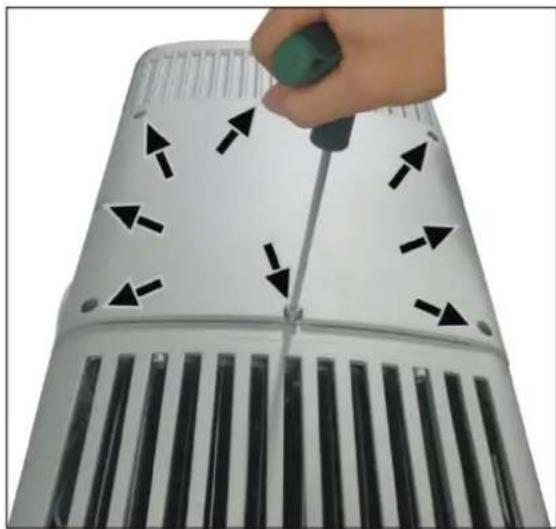
- See illustration on right. Use a 5 mm Allen key (hex wrench) to remove the eight top cover screws (arrowed). Lift the top cover off the fixture. For ease of access – and if it is safe to do so – you can unclip the safety cable and remove the cover completely from the fixture.
Reinstalling the top cover
To reinstall the top cover:
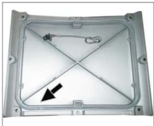
- See illustration on right. Check the silicone seal in the top cover. If it is not in perfect condition, replace it with a new item from Martin.
-
See illustration on right. If you unclipped the top cover safety cable, reattach it with its carabiner hook (arrowed) so that it will catch the top cover and prevent it from falling.
-
Place the top cover loosely over the top of the fixture so that air can enter and leave the fixture but debris cannot enter.
-
Obtain a silica gel desiccant bag (P/N 37220000) from Martin. Do not remove the silica gel bag from its sealed moisture-proof bag until you are ready to install it as described below.

-
See illustration on right. Open the Service → Evaporation Mode control menu and select PASSWORD. Scroll to the user password (default = 123) and press ENTER.
-
Select COVER OPEN and press ENTER.
-
Select EVAPORATION ON to set the fixture to Evaporation Mode. This allows warm, humid air to leave the fixture and dry air to enter the fixture. WAIT will appear in the display.
-
After approx. 15 minutes the display will stop showing WAIT and start showing CLOSE COVER. Press ENTER.

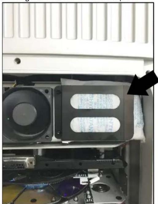
- See illustration on right. Remove the silica gel desiccant bag from its sealed moisture-proof
bag. Move the top cover to one side for access, if necessary, then install the silica gel bag under the clip (arrowed) in the top of the fixture as shown.
-
Check that the top cover safety cable is correctly installed.
-
Reinstall the eight top cover screws by first inserting them finger-tight. Then use a torque driver and cross-tighten the screws in a diagonal pattern, increasing torque gradually in stages until you reach a torque of 1.9 – 3.5 Nm.
Replacing a rotating gobo
Gobos are user-replaceable, and you can replace them with custom gobos made to your own design.
Gobos 1 – 4 and gobo 7 are printed/coated glass and share the same specifications, but gobos 5 and 6 are textured glass and have different specifications to the others. See 'Gobos' on page35. When replacing the textured glass gobos in goboholder 5 and 6 with standard glass gobos, you must use the long spring.
See illustration below. The goboholders have magnets (arrowed) that the fixture uses to recognize the position of the gobo wheel and gobos. If you replace gobos, install gobos and goboholders in their original orientation, using the magnet as reference.

The rotating gobos in the Exterior Projection 1000 are installed in goboholders that clip into the rotating gobo wheel.
Keep gobos perfectly clean and free of oil and grease from your fingers. Put on clean, lint-free gloves while handling gobos.
To replace a gobo:
-
Remove the top cover as described under 'Removing and reinstalling the top cover' earlier in this chapter.
-
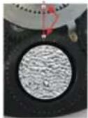
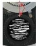
See illustrations below. Position the alignment mark (arrowed) in each goboholder at a reference point such as the midpoint between the end of the motor mounting plate and multi-connector. Remove and reinstall goboholders with alignment marks in the same position so that you keep gobos in the same orientation.

GOBO 1
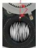
GOBO 5
GOBO 2

GOBO 6

GOBO 3
GOBO 7

GOBO 4

- See illustration below. Pull the goboholder away from the gobo wheel, then lift it up out of the wheel.
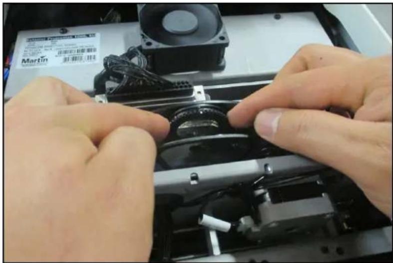
- See illustration on right. Place the goboholder on a clean, flat work surface with the teeth facing downwards. The gobo is held in place in the goboholder by a spring. Taking care to avoid scratching or applying pressure to the gobo, lever the end of the spring out, remove the spring and then lift the gobo out of the goboholder.

- See illustration below. Wearing clean gloves, hold the gobo with the dark side facing up. Match up the alignment marks (arrowed) in the gobo and goboholder. Lay the new gobo flat in the goboholder.

Gobos 5 and 6 only
Gobos 5 and 6 are textured glass and require a thrust washer. See illustration below. Place the black thrust washer (arrowed) over the gobo before you go on to the next step.
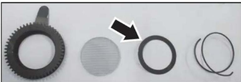
- See illustration below. Note the end of the gobo retaining spring with the bend (arrowed) that is used for levering the spring out of the goboholder. Making sure that the bend in the spring is at the top (as shown below), closest to you, press the spring down into the goboholder until the spring clips into its recess in the goboholder. Check that the spring is secure and that the gobo is still sitting flat in the goboholder.

- Hold the goboholder up to the rotating gobo wheel in its original position. Rotate it until the alignment mark in the goboholder lines up with the reference point as shown in Step 3.
- See illustrations below. Push the goboholder into position, sliding the tongue that sticks out from the goboholder into position (arrowed) behind the gobo activation cog, pressing against the gobo wheel.


-
Check that the goboholder is held securely. Rotate the whole gobo wheel with your finger and check that the goboholder rotates in the wheel while you rotate the gobo wheel. If the goboholder does not rotate, it is not correctly installed and its teeth are probably not engaged correctly in the teeth in the gobo wheel. Lift the goboholder out of the gobo wheel and reinstall it correctly.
-
Reinstall the top cover as described earlier in this chapter.
Installing a glare shield accessory
A glare shield is available from Martin as an optional accessory for the Exterior Projection 1000 (see 'Accessories' on page 54). The shield reduces stray light and is also recommended to help protect the fixture from damage caused by the sun shining on the front of the fixture. The glare shield can be installed in seconds.
To install a glare shield:
- See illustration below. Remove the plugs from the holes (arrowed) for the six front accessory mounting screws.

- Six 3 mm Allen (hex) screws are supplied with the glare shield. Fasten the glare shield securely to the fixture using the six screws. Use a torque driver to tighten the screws to a torque of 0.7 - 1.1 Nm .
Remote Device Management (RDM)
The Exterior Projection 1000 features Remote Device Management (RDM) capability. RDM lets you get information from the fixture and change settings in the fixture remotely over the DMX data link.
To communicate with the fixture via RDM, use an RDM-compatible DMX controller.
Before you can communicate with fixtures, you must send a scan command ('Disc Unique Branch') from the RDM controller to detect the devices on the data link. For other details of communication with fixtures, see the RDM-compatible DMX controller's user manual.
RDM commands are normally referred to as Parameter IDs or PIDs. The Exterior Projection 1000 responds to the following Parameter IDs:
Device discovery
| Parameter ID |
| DISC_UNIQUE_BRANCH |
| DISC_MUTE |
| DISC_UN_MUTE |
Device management
| Parameter ID GET SET | ||
| COMMS_STATUS | √ | |
| QUEUED_MESSAGE | √ | |
| STATUS_MESSAGES | √ | |
| STATUS_ID_DESCRIPTION | √ | |
| CLEAR_STATUS_ID | √ | |
| SUPPORTED_PARAMETERS | √ | |
| PARAMETER_DESCRIPTION | √ | |
| DEVICE_INFO | √ | |
| DEVICE_MODEL_DESCRIPTION | √ | |
| MANUFACTURER_LABEL | √ | |
| DEVICE_LABEL | √ | √ |
| FACTORY_DEFAULTS | √ | √ |
| SOFTWARE_VERSION_LABEL | √ | |
| DMX_PERSONALITY | √ | √ |
| DMX_PERSONALITY_DESCRIPTION | √ | |
| DMX_START_ADDRESS | √ | √ |
| SLOT_DESCRIPTION | √ | |
| SENSOR_DEFINITION | √ | |
| SENSOR_VALUE | √ √ | |
| DEVICE HOURS | √ √ | |
| LAMP_HOURS | √ √ | |
| DEVICE_POWER_CYCLES | √ √ | |
| IDENTIFY DEVICE | √ | √ |
| RESET DEVICE | √ | |
The commands that execute the PIDs in the table above are displayed differently on different RDM controllers.
The Exterior Projection 1000 sends warnings and error message codes via RDM if you send a command from the RDM controller. See 'Warnings and error messages' on page 50 for a list of possible codes.
DMX protocol
| Channel Value Function | Fade Status | Default Value | ||
| 1 | 0 - 1920 - 4950 - 200201 - 210211 - 255 | StrobeShutter closedShutter openStrobe (slow → fast)Shutter openRandom strobe (slow → fast) | Snap 30 | |
| 2 | 0 - 65335 | DimmerClosed → open | Fade 0 | |
| 3 | ||||
| 4 | 0 - 255 | Cyan0 → 100% | Fade 0 | |
| 5 | 0 - 255 | Magenta0 → 100% | Fade 0 | |
| 6 | 0 - 255 | Yellow0 → 100% | Fade 0 | |
| 7 | 01224364860728496108120132144156168180192-200 | Color selectionContinuousOpenSplit open/Color 1Color 1Split Color 1/Color 2Color 2Split Color 2/Color 3Color 3Split Color 3/Color 4Color 4Split Color 4/Color 5Color 5Split Color 5/Color 6Color 6Split Color 6/Color 7Color 7Split Color 7/OpenOpenSteppedSlot 1Slot 2Slot 3Slot 4Slot 5Slot 6Slot 7Open | Snap 0 | |
| 8 | Gobo selectionIndexingOpen goboGobo 1 indexingGobo 2 indexingGobo 3 indexingGobo 4 indexingGobo 5 indexingGobo 6 indexingGobo 7 indexingRotationGobo 1 rotationGobo 2 rotationGobo 3 rotationGobo 4 rotationGobo 5 rotationGobo 6 rotationGobo 7 rotationOpen gobo | Snap 0 | ||
| 9 | 0 - 655350 - 600 (2,88)601 - 32130(125,130)32131 - 32895(128,127)32896 - 64425(251,169)64426 - 65535(255,255) | Gobo indexed positionIf indexing is selected on channel 8Indexed position, 0° Index at 32768Gobo rotation direction and speedIf rotation is selected on channel 8No rotation (gobo indexed at 0°)Rotation CW fast → CW slowNo rotation (gobo stops at current position)Rotation CCW slow → CCW fastNo rotation (gobo indexed at 90°) | Fade 32768 | |
| 10 | ||||
| 11 | 0 - 255 | Animation indexingIndexed position 45° - 156° | Fade 0 | |
| 12 | 0 - 23 - 126127 - 129130 - 253254 - 255 | Animation rotationStopCW fast → slowStop (wheel stops at current position)CCW slow → fastStop | Fade 0 | |
| 13 | 0 -255 | FrostNo diffuser → full diffuser | Fade 0 | |
| 14 | 0 - 56 - 1011 - 1516 - 2021 - 2526 - 255 | PrismOpen3-facet prism indexingLinear prism indexing3-facet prism rotationLinear prism rotationNo function | Snap 0 | |
| 15 | 0 – 255 | Prism indexed positionIf channel 14 set to DMX value 6-15Indexed position (0° index at 128) | Fade 128 | |
| 0 – 23 – 126127 – 129130 – 253254 – 255 | Prism rotationIf channel 14 set to DMX value 16-25No rotation (prism indexed at 0°)Rotating CW Fast → CW SlowNo rotation (prism stops at current position)Rotating CCW Slow to CCW FastNo rotation (prism indexed at 45°) | |||
| 16 | 0 – 65535 | ZoomWide → narrow | Fade 32768 | |
| 17 | ||||
| 18 | 0 – 65535 | FocusFar → near | Fade 32768 | |
| 19 | ||||
| 20 | 0-910-1415-2930-3435-3940-4445-4950-5455-5960-6465-6970-255 | Fixture control/settingsNo functionReset fixtureNo functionPrecise gobo indexing ONPrecise gobo indexing OFF (default)Parameter shortcuts = ON (default)Parameter shortcuts = OFFAuto-blackout = ONAuto-blackout = OFF (default)Illuminate display on fixtureTurn off display on fixtureNo function | Snap 0 | |
Control menus
To access the control menus, press the MENU button and hold for three seconds. Use the UP ▲ and DOWN ▼ buttons to navigate the menus. Select menu options using the ENTER button. Exit menus using the MENU button.
| DMX Address | 1~XXX Set fixture's DMX address | ||||
| Program show | Set scene total 1-20 | Set total number of scenes in standalone show (default = 20) | |||
| Edit scene Scene 1~20 | Strobe | Set value or percentage for each effect in scene | |||
| Dimmer | |||||
| Cyan | |||||
| Etc... | |||||
| Set show times | Set fade time 0~120s | Default 0.0 seconds | |||
| Set hold time 0~600s | Default 4.0 seconds | ||||
| Manual mode | Manual test | Strobe 0-255 | Manually control all fixture's effects | ||
| Dimmer 0-100% | |||||
| Cyan 0-255 | |||||
| Etc... Etc... | |||||
| Reset functions | All | No | Reset all effects | ||
| Yes | |||||
| Color/CMY | No | Reset color wheel and CMY | |||
| Yes | |||||
| Gobo | No | Reset gobo wheel | |||
| Yes | |||||
| PrismFrostFocusZoom | No | Reset prism, frost, focus and zoom | |||
| Yes | |||||
| Animation | No | Reset gobo animation wheel | |||
| Yes | |||||
| Factory default | Yes/No | Return fixture to factory default settings | |||
| Display setting | Inverse | On/Off | Flip readout in display panel through 180° | ||
| Display auto off | No/Yes(1 minute) | Display panel sleeps after 1 minute | |||
| Intensity | 0%-100% | Adjust display panel intensity | |||
| Lock display | On | Activate display locking (if display is locked, hold Menu key pressed for 3 seconds, then enter service password (111) to unlock) | |||
| Off | |||||
| Set password | 0...999 | Set user password (default = 123) | |||
| Fixture Config | Host/Client Host/Client | Fixture acts as host or client in host/client operationImportant: Set only one fixture to be host! | |||
| Offline mode | Run show | When no DMX signal is present, fixture runs standalone show | |||
| DMX last state | When no DMX signal is present, fixture displays the last effect it was displaying before the DMX signal stopped | ||||
| Black out | When no DMX signal is present, fixture blacks out | ||||
| Service | Fixture status | LED Temperature Temperature of LED engine in °C | |||
| Power-on Hours | Number of hours fixture has been powered on since manufacture | ||||
| Lamp Hours | Number of hours light output has been activated since manufacture (or since counter last reset).Press Enter, then use service password (123) to access option to reset lamp hours to zero | ||||
| Software Version V x.x | x | Currently installed software (firmware) version | |||
| Fixture offset | Cyan -128~127 | Note: For use by Martin Service!Enter user password (default = 123) or service password (111) for access to effect offsets. Then set an offset in each effect's home position. | |||
| Magenta -128~127 | |||||
| Yellow -128~127 | |||||
| Color Selection -128~127 | |||||
| Etc... ... | |||||
| Evaporation mode | Password 0 ... 999 | Enter user password (default = 123) or service password (111) to put fixture into Evaporation Mode. To clear humidity, open top cover slightly, then press Enter. When message to close cover appears in display, close top cover, then press Enter. | |||
Warnings and error messages
The Exterior Projection 1000 monitors its own operation and is capable of self-diagnosis. If an operating parameter such as ambient temperature is exceeded or if an error occurs, the fixture displays a warning or error message in its onboard LCD display.
If the fixture displays a warning or error message, it can also send a four-character code to an RDM controller. You may need to use a command to retrieve these codes from the fixture.
The following table gives the meaning of the warning and error message codes in RDM:
| Message in display RDM code Notes | ||
| Environment temp out of range | 8003 Ambient temperature exceeded | |
| Err Animation 901B Animation system error | ||
| Err Animation Rot 901C Animation wheel rotation error | ||
| Err Focus 901D Focus sensor error | ||
| Err Zoom 901E Zoom error | ||
| Err Frost 907F Frost error | ||
| Err Color Wheel | 9015 Color wheel error | |
| Err Gobo Wheel | 9017 Gobo wheel error | |
| Err Gobo ind/rot | 9018 Gobo indexing/rotation error | |
| Err Cyan | 9022 Cyan error | |
| Err Magenta | 9023 Magenta error | |
| Err Yellow | 9024 Yellow error | |
| Err 3_Facet_Prism | 9028 3-facet prism error | |
| Err Prism Rot | 9029 Prism rotation error | |
| CMY Fan 1 | 9056 CMY cooling fan 1 not running | |
| PCBA Fan | 9057 PCBA cooling fan not running | |
| PSU Fan | 9059 Internal PSU fan error | |
| CMY Fan 2 | 905A CMY cooling fan 2 not running | |
| Err Line Prism | 9062 Linear prism error | |
| Gobo Wheel Fan | 90AE | Gobo wheel cooling fan not running |
Troubleshooting
This section provides some suggestions for solving possible problems:
| Symptom | Potential cause | Remedies |
| No light from fixture Power supply | ply issue such as faulty connector or damaged cable. | Ensure that mains supply is connected and supplying power to the fixture.Check all power connections and cables. |
| Reduced light output | Fixture may be close to maximum operating temperature and automatically reducing output to protect from overheating. | Check that maximum ambient temperature (45°C) has not been exceeded.Ensure that fixture is clean and that there is free airflow around fixture, especially around grills at back of fixture. |
| Fixture does not respond correctly to DMX control | Incorrect DMX setup.Fault in the DMX network due to connector or cable damage or potential interference from proximity to a high voltage installation.Internal fault. | Check DMX addressing.Check all DMX cables and connections.Ensure that DMX link is terminated.Attempt to control fixture with another DMX control device.Move or shield DMX link if it is close to an unshielded high-voltage installation.Contact your Martin authorized distributor or service center for assistance. |
| Condensation visible on inside of front glass | Humidity inside fixture. Condensation inside the fixture is normal in some atmospheric conditions. The fixture will gradually expel humidity via its Gore-Tex pressure relief valve as it cycles on and off.If required, you can remove excessive humidity by following the directions given in ‘Removing and reinstalling the top cover’ starting on page 36. | |
Specifications
Physical
Length (head horizontal) 702 mm (27.7 in.)
Width 417 mm (16.5 in.)
Height (head horizontal)....618 mm (24.4 in.)
Height (head vertical)....771 mm (30.4 in.)
Weight 50 kg (110 lbs.)
All figures include mounting yoke

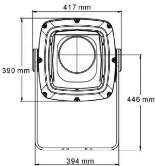

Dynamic Effects
Color mixing.....CMY independently variable 0-100%
Color wheel....7 interchangeable colors plus open
Rotating gobos 7 rotating gobos plus open, indexing, variable rotation
Gobo animation wheel..... Indexing, continuous rotation with variable angle, speed and direction
Zoom .... Motorized, 10° - 44° (cutoff angles)
Focus....Motorized, variable, 3 m (9.8 ft.) to infinity
Prism ...... Prism wheel with 2 interchangeable prisms, prism rotation and indexing
Frost filter....Motorized, variable
Dimming ...... Electronic, 0-100% constantly variable
Shutter......Electronic, strobe and pulse effects, instant open and blackout
Control and Programming
Control options ...... DMX, RDM, stand-alone
Configuration, addressing and status......Onboard control panel with OLED display or via RDM
8-bit control.....CMY, color selection, gobo selection, prism, frost, animation
16-bit control......Gobo indexing and rotation, zoom, focus and intensity
DMX channels 20
DMX compliance ...... USITT DMX512-A
RDM compliance ANSI/ESTA E1.20
Optics
Light source 440 W white light LED engine
CRI (Color Rendering Index)....72
Color temperature 6500 K (±250 K)
LED lifetime 20 000 hours (to >70% luminous output)*
LED manufacturer .... Appotronics
*Figure obtained under manufacturer's test conditions
Photometric Data
Cut-off angle 10° - 44°
Luminous intensity:
Zoom angle Total output Center peak
| 10° | 11 500 lumens 731 000 cd |
| 16° | 15 000 lumens 311 000 cd |
| 40° | 16 800 lumens 42 000 cd |
Construction

Housing Cast aluminum
Finish....Hard-anodized, white or metallic grey lacquered
Front glass....5 mm (0.2 in.) anti-reflection coated tempered glass
Ingress protection....IP 66
Impact resistance IK08 (with control panel / display cover plate installed)
Corrosion resistance ....C5-M (very high corrosivity / marine, ISO 12944)
EPA (Effective Projected Area 0.28m 4 )
RoHS compliant
Gobos
Suitable material....Metal or borosilicate glass, coatings heat-resistant to 450°C (842°F)
Gobo diameter.... 30.0 mm +0/-0.3 mm (1.2 in. +0/-0.02 in.)
Maximum image diameter....26 mm (1.02 in.)
Gobo thickness, minimum 1.1 mm ±0.1 mm (0.045 ±0.004 in.)
Gobo thickness, maximum 3.0 mm ±0.3 mm (0.118 in. ± 0.012 in.)*
*Gobos thicker than 2.5 mm require a shorter spring in the goboholder
Installation
Mounting....Adjustable yoke
Suitable for wet locations. Do not immerse in water.
Orientation.....Any (sides must be kept vertical)
Minimum distance to illuminated surfaces 0.5 m (20 in.)
Connections
Power cable entry.... IP66 cable gland
Power connection....1.8 m (5.9 ft.) cable tail with bare ends
Power cable type....EU models: H07RN-F 450/700 V, ∅ 10 mm
US models: SJTW 14AWG, 300 V, ∅ 9.3 mm (0.37 in.)
Data cable entry IP66 cable gland
Data connection 1.8 m (5.9 ft.) combined input + output cable tail with bare ends
Electrical
AC power....100-120/200-277 V nominal, 50/60 Hz
Power supply....Auto-ranging electronic switch-mode
Typical half-cycle RMS inrush current....15.5 A
Surge protection 4 kV
Idle power (zero intensity, no effects applied)....75 W
Typical Power and Current
120 V, 60 Hz....645 W, 5.5 A, PF 0.98
230 V, 50 Hz....635 W, 2.9 A, PF 0.95
277 V, 60 Hz....635 W, 2.6 A, PF 0.90
Figures are typical, not maximum. Measurements made at nominal voltage with all LEDs at full intensity. Allow for a deviation of +/- 10%. PF = Power Factor.
Thermal
Cooling ...... Convection, internal forced air
Total heat dissipation (calculated)....2350 BTU/hr.
Maximum surface temperature....85°C (185°F)
Maximum ambient temperature (Ta max.)....45° C (113° F)*
Minimum ambient temperature (Ta min.)....-30° C (-22° F)**
*Above this temperature the fixture regulates output to protect from overheating.
**For instant wake-up with no warm-up mode, leave power applied constantly in ambient temperatures below 0°C ( 32°F ).
Approvals


Global CB Certification/IECEE ....IEC 60598-2-5 (IEC 60598-1)
EU safety...... EN 60598-2-1, EN 60598-2-5 (EN 60598-1), EN 62471, EN 62493
EU EMC......EN 55015, EN 55032, EN 55103-2, EN 61000-3-2, EN 61000-3-3,
EN 61000-4-2, EN 61000-4-3, EN 61000-4-4, EN 61547
US safety....ANSI/UL 1598
US EMC....CFR 47 Part 15 Class A
Canadian EMC ICES-003 Class A, NMB 3-5 Class A
Australia/NZ....RCM
Included Items
Silica gel desiccant bag.... P/N 37220000
Two gobo retaining springs, extra length, for use with non-textured gobos
Accessories
Glare Shield, Exterior Projection 1000 P/N 91611768
'Line it Up' Projection Setup Gobo for Exterior Projection 1000 P/N 91616075
Gobo Ring, Outer Diameter 30 mm, Set of 10....P/N MAR-91611851
Protection Spring for Exterior Projection 1000 (use during transport) P/N 91611097
Related Items
Martin Companion software suite.... Free download from www.martin.com
Martin Companion Cable USB/DMX hardware interface P/N 91616091
Martin RDM 5.5 Splitter P/N 90758150
Spare Parts
Silica Gel Desiccant Bag in sealed foil pack P/N 37220000
Exterior Projection 1000 Goboholder with Magnet (incl. washer + short spring).... P/N 50482185
Exterior Projection 1000 Goboholder with Magnet (incl. washer + long spring)..... P/N 50482186
Ordering Information
EU models
Exterior Projection 1000, EU, Aluminum P/N 90512000
Exterior Projection 1000, EU, White P/N 90512015
US models
Exterior Projection 1000, US, Aluminum P/N 90512005
Exterior Projection 1000, US, White P/N 90512010
Specifications subject to change without notice. Please see the Martin website at www.martin.com for latest specifications.

Disposing of this product
Martin products are supplied in compliance with Directive 2012/19/EC of the European Parliament and of the Council of the European Union on WEEE (Waste Electrical and Electronic Equipment), where applicable.
Help preserve the environment! Ensure that this product is recycled at the end of its life. Your supplier can give details of local arrangements for the disposal of Martin products.
Notes
Notes
Notes
Notes
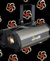
- EXTERIOR PROJECTION 1000 USER MANUAL
- IMPORTANT! REMOVE TRANSPORT PROTECTION BEFORE USE
- DIMENSIONS
- TABLE OF CONTENTS
- SAFETY INFORMATION
- WARNING
- READ THE SAFETY PRECAUTIONS IN THIS MANUAL BEFORE INSTALLING, OPERATING OR SERVICING THIS PRODUCT
- TECHNICAL SUPPORT
- USER DOCUMENTATION
- PROTECTION FROM ELECTRIC SHOCK
- PROTECTION FROM BURNS AND FIRE
- PROTECTION FROM EYE INJURY
- PROTECTION FROM INJURY
- INTRODUCTION
- BEFORE USING FOR THE FIRST TIME
- TRANSPORTING THE FIXTURE
- FIXTURE OVERVIEW
- PHYSICAL INSTALLATION
- PROTECTION FROM THE SUN
- COOLING
- PROTECTION FROM MOISTURE
- AVOIDING GALVANIC CORROSION
- MOUNTING THE FIXTURE
- INSTALLING ON A RIGGING TRUSS
- ANCHORING TO A SURFACE OR STRUCTURE
- SAFETY CABLE ATTACHMENT
- ADJUSTING AIMING (PAN AND TILT)
- AC POWER
- READ 'SAFETY INFORMATION' ON PAGE 5 BEFORE CONNECTING THE FIXTURE TO AC MAINS POWER. LOCK OUT POWER TO THE ENTIRE INSTALLATION BEFORE WORKING ON CABLES AND CONNECTIONS
- PROTECTING CONNECTIONS FROM MOISTURE
- CONNECTING TO AC MAINS POWER
- INSTALLING A TEMPORARY POWER PLUG
- CONTROL DATA LINK
- CONNECTING THE DATA LINK
- FIXTURE SETUP
- USING THE CONTROL MENUS
- NAVIGATING IN THE CONTROL MENUS
- PASSWORDS
- SETTING A DMX ADDRESS
- PROGRAMMING A STANDALONE SHOW
- MANUAL CONTROL MODE
- MANUAL TEST / MANUAL SINGLE SCENE DISPLAY
- RESETTING EFFECTS
- RETURNING TO FACTORY DEFAULTS
- DISPLAY SETTINGS AND USER PASSWORD
- DISPLAY INVERSE
- DISPLAY AUTO TURN OFF
- DISPLAY INTENSITY
- LOCKING THE DISPLAY
- SETTING THE USER PASSWORD
- FIXTURE STATUS
- FIXTURE CONFIGURATION (INCLUDING HOST/CLIENT OPERATION)
- HOST/CLIENT OPERATION – IMPORTANT GUIDELINES
- SETTING UP HOST/CLIENT OPERATION
- OFFLINE MODE – BEHAVIOR WHEN NO DMX OR HOST SIGNAL IS RECEIVED
- SETTING EFFECT OFFSETS
- SETUP VIA RDM
- EFFECTS
- STROBE / SHUTTER
- ELECTRONIC DIMMING
- CMY COLOR MIXING
- COLOR WHEEL
- GOBOS
- CUSTOM GOBOS
- GOBO INDEXING ANGLES AND PRECISE GOBO INDEXING
- ANIMATION EFFECT
- ANIMATION HORIZONTAL 156°
- PRISM
- FROST
- FOCUS
- ZOOM
- OPERATION
- THERMAL CONDITIONS
- PROJECTION DATA
- SERVICE AND MAINTENANCE
- FIRMWARE
- CLEANING
- MANAGING HUMIDITY
- GENERAL
- SEALS AND SEALING SURFACES
- PRESSURE RELIEF VALVES
- REMOVING AND REINSTALLING THE TOP COVER
- REMOVING THE TOP COVER
- REINSTALLING THE TOP COVER
- REPLACING A ROTATING GOBO
- GOBOS 5 AND 6 ONLY
- INSTALLING A GLARE SHIELD ACCESSORY
- REMOTE DEVICE MANAGEMENT (RDM)
- CONTROL MENUS
- WARNINGS AND ERROR MESSAGES
- TROUBLESHOOTING
- SPECIFICATIONS
- PHYSICAL
- DYNAMIC EFFECTS
- CONTROL AND PROGRAMMING
- OPTICS
- PHOTOMETRIC DATA
- CONSTRUCTION
- INSTALLATION
- CONNECTIONS
- ELECTRICAL
- TYPICAL POWER AND CURRENT
- THERMAL
- APPROVALS
- INCLUDED ITEMS
- ACCESSORIES
- RELATED ITEMS
- SPARE PARTS
- ORDERING INFORMATION
- EU MODELS
- US MODELS
- DISPOSING OF THIS PRODUCT
Brand : MARTIN
Model : Exterior Projection 1000
Category : Lighting