99-8725B - Car stereo Metra - Free user manual and instructions
Find the device manual for free 99-8725B Metra in PDF.

| Product Type | Car Stereo Installation Kit |
| Model | 99-8725B |
| Brand | Metra |
| Compatible Vehicle | Select Chrysler, Dodge, Jeep, and Ram models (2008-2012) |
| Material | High-grade ABS plastic |
| Color | Black (textured finish) |
| Dimensions (L x H x D) | 7.0 x 4.5 x 1.0 inches |
| Weight | 0.6 lbs |
| Radio Size Accepted | Single DIN or Double DIN (with included trim ring) |
| Included Items | Dash kit, mounting brackets, screws, and installation instructions |
| Installation Difficulty | Moderate (DIY-friendly with basic tools) |
| Maintenance | Wipe with a dry cloth; avoid harsh chemicals |
Frequently Asked Questions - 99-8725B Metra
User questions about 99-8725B Metra
0 question about this device. Answer the ones you know or ask your own.
Ask a new question about this device
Download the instructions for your Car stereo in PDF format for free! Find your manual 99-8725B - Metra and take your electronic device back in hand. On this page are published all the documents necessary for the use of your device. 99-8725B by Metra.
USER MANUAL 99-8725B Metra
natural_image
Interior view of a car dashboard with air filters, steering wheel, and digital display (no visible text or symbols)Mercedes C Class 2012-2015
KIT FEATURES
• ISO DIN radio provision with pocket
• ISO DDIN radio provision
- Includes parts to relocate the hazard switch panel
- Painted matte black
KIT COMPONENTS
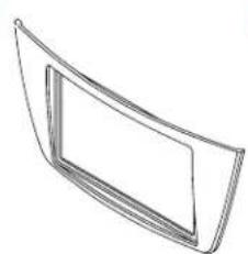
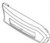
A) Radio trim panel B) Radio brackets C) Hazard switch housing D) Hazard switch bracket E) Hazard switch housing spacer F)
• G) (12) #8 x 3/8" Phillips screws • H) (1) #8 x 1 Phillips screw
A
natural_image
Simple line drawing of a curved panel or frame with no text or symbols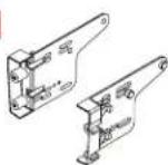

E

F

G
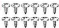

TABLE OF CONTENTS
Dash Disassembly....2-3
Kit Preparation 4-5
Kit Assembly
-ISO DIN radio provision with pocket 6
-ISO DIN radio provision with pocket 7
WIRING & ANTENNA CONNECTIONS (sold separately)
Wiring Harness: TBA
Antenna Adapter: 40-EU56
Steering wheel control interface: ASWC-1 Pocket
TOOLS REQUIRED
- Panel removal tool • Phillips screwdriver
- Torx T20 screwdriver - Cutting tool
CAUTION! All accessories, switches, climate controls panels, and especially air bag indicator lights must be connected before cycling the ignition. Also, do not remove the factory radio with the key in the on position, or while the vehicle is running.
DASH DISASSEMBLY
Radio removal
- Unclip, unplug, and removethe dashboard trim panel abovether radio. This panel also includes the center a/cvents. (Figure A)
- Unscrew(2)TorxT20screwsonthe topoftheradio,justhalfway(abouta halfinch),thenpushthescrewsdown toreleasetheradio.Pulltheradiout, thenunplug.(FigureB)

natural_image
Interior view of a car dashboard and steering wheel (no text or symbols visible)(FigureA)(FigureC)
Display screen removal
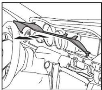
- Unclipandremovethelowertrimfrom thespeedometercluster.(FigureC)
- Unclipandremovetheuppertrimfrom thespeedometercluster.(FigureD)
Continuedonthenextpage

natural_image
Technical line drawing of a mechanical component with no visible text or symbols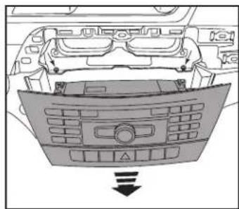
natural_image
Top-down view of a car dashboard with control panel and directional arrow (no text or symbols)(FigureB)(FigureD)
natural_image
Technical line drawing of a mechanical component with no visible text or symbolsDASH DISASSEMBLY (CONT.)
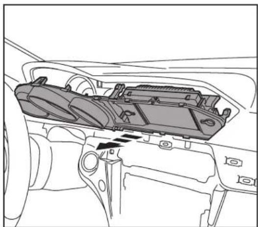
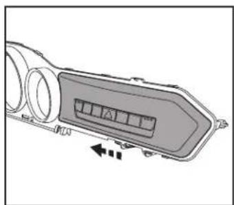
- Removethedisplayscreentrimpanels totheleftandrightofthescreenby pushinginwardstowardthescreen.This willaidinremovingthespeedometer trimplateinthenextstep.(FigureE)
- Unclipandremovethespeedometer trimplate. Thispanelisheldonbyclips atthetop, andhingesonthebottom. Thistrimplate will also include the displayscreen. Unplugthedisplay screentocompletelyremovethe trimplate. (FigureF)
ContinuetoKitPreparation

natural_image
Line drawing of a car interior showing dashboard, air vent, and camera module (no text or symbols)(FigureE)(FigureF)
natural_image
Technical line drawing of a car interior showing internal components and a directional arrow (no text or symbols)KIT PREPARATION
- Unclipandremovethedisplayscreen fromthespeedometertrimplate. (FigureA)
- Cutthespeedometertrimplateas shown.(FigureB)
- Remove(4)TorxT20screwssecuringthe hazardswitchtotheradio,thenremove theswitch.
- Placethehazardswitchintothehazard switchhousing.
Continuedonthenextpage
natural_image
Technical illustration of a heat exchanger or cooling unit with cooling fins and cooling fins (no text or symbols)(FigureA)

text_image
Removeshadedarea(FigureB)
KIT PREPARATION (CONT.)
- Securethe hazardswitchbracket tothe hazardswitchhousing usingthe(4) #8x3/8"Phillipsscrewsprovided.This willsecurethehazardswitchinplace. (FigureC)
- Slidethehazardassemblyontothe speedometertrimplate.(FigureD)
- Placethe hazardousswitchhousingspacer ontothespeedometertrimplate,then securetheentireassemblytothetrim plateusingthe(1)#8x1Phillipsscrew provided.(FigureE)
- Routethehazardswitchwiringharness tothedisplayscreenarea.
- Connect the hazard switch harness to the hazard switch, then reassemble the top portion of the dash in reverse order of disassembly, steps 3-6 (skip step 5).
natural_image
Technical line drawing of a mechanical component with internal parts and alignment lines (no text or symbols)(FigureC)(FigureD)(FigureE)
natural_image
Diagram of a vehicle air intake manifold with directional arrows indicating flow or movement (no text or symbols)
natural_image
Technical line drawing of a mechanical component with a close-up detail showing a small component (no text or symbols)ContinuetoKitAssembly
KIT ASSEMBLY
ISO DIN radio provision with pocket
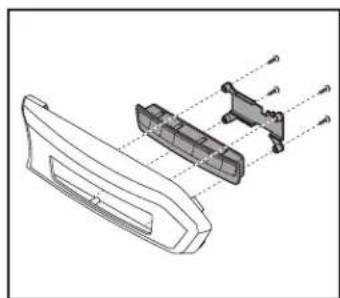
- Securethe radiobrackets tothe radio trimpanel usingthe(4)#8x3/8" Phillipsscrewsprovided.(FigureA).
- Slidethe pocket into the bracket/panel assembly, then secure it using the (4) #8x3/8" Phillipsscrews provided. (FigureB)
- RemovethemetalDINsleeveandtrim ringfromtheaftermarketradio.
- Slidetheradiointothebracket/pocket assembly, thensecureitusing the screwssuppliedwiththeradio. (FigureC)
natural_image
Technical line drawing of a mechanical bracket assembly (no text or symbols)(FigureA)
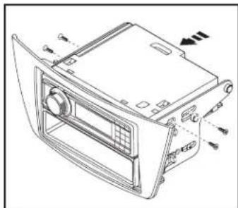
- Locatethefactorywiringharnessand antennaconnectorinthedashand completeallnecessaryconnectionstotheradio.Metrarecommendsusing thepropermatingadapterfromMetra and/orAxxess.Testtheradioforproper operation.
- Reassemblethedashinreverse orderofdisassemblytocompletethe installation.
natural_image
Technical line drawing of a device rear panel with control panel and ventilation slots (no text or symbols)(FigureC)

natural_image
Technical line drawing of a car front panel assembly (no text or symbols)(FigureB)
KIT ASSEMBLY
ISO DDIN radio provision
-
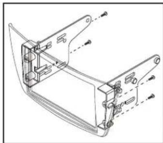
Securethe radiobrackets tothe radio trimpanel usingthe(4)#8x3/8" Phillipsscrewsprovided.(FigureA).
-
Slidethe radio into the bracket/panel assembly, then secure it using the screw supply with the radio. (Figure B)
-
Locatethefactorywiringharnessand antennaconnectorinthedashand completeallnecessaryconnectionstotheradio.Metrarecommendsusing thepropermatingadapterfromMetra and/orAxxess.Testtheradioforproper operation.
-
Reassemblethedashinreverse orderofdisassemblytocompletethe installation.

natural_image
Technical line drawing of a mechanical bracket assembly (no text or symbols)(FigureA)(FigureB)

natural_image
Technical line drawing of a device casing with mounting brackets and control panel (no text or symbols)IMPORTANT
If you are having difficulties with the installation of this product, please call our Tech Support line at 1-800-253-TECH. Before doing so, look over the instructions a second time, and make sure the installation was performed exactly as the instructions are stated. Please have the vehicle apart and ready to perform troubleshooting steps before calling.

KNOWLEDGE IS POWER
Enhance your installation and fabrication skills by supplying in the most recognized and supported
mobile electronics school in our industry.
Log onto www.installennstitute.com or call
800-354-6782 for more information and take steps toward a better tomorrow.

Metra recommends MECP certified technicians

natural_image
Interior view of a modern car dashboard with air condition meters and control panel (no visible text or symbols)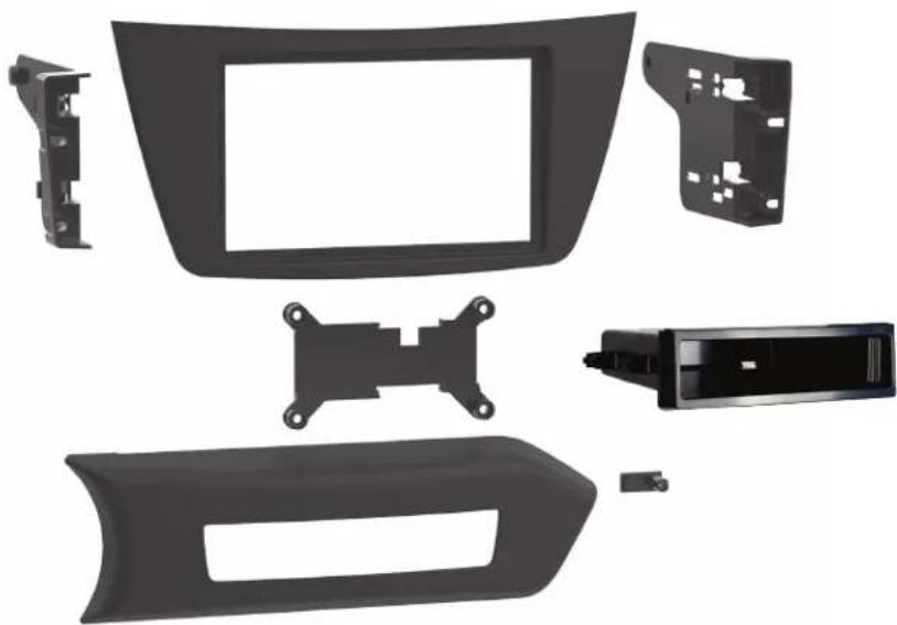
natural_image
Exploded view of a car dashboard frame with plastic components and mounting brackets (no text or symbols visible)HARDWARE INCLUDED

natural_image
Illustration of a row of ten identical screw fasteners (no text or symbols)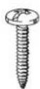
Mercedes-Benz C-Class 2012-2015
D ISO DDIN radio provision
S ISO DIN radio provision with pocket
P Painted matte black
This kit provides the ability to install an ISO DIN radio with pocket, as well as an ISO DDIN aftermarket radio. Painted matte black to match the original dash appearance.
KIT COMPONENTS
- Radio trim panel
- Radio brackets
- Hazard switch housing
- Hazard switch bracket
• Hazard switch housing spacer - Pocket
• (12) #8 x 3/8" Phillips screws
• (1) #8 x 1" Phillips screw
WIRING & ANTENNA CONNECTIONS
(sold separately)
- Wiring Harness: TBA
- Antenna Adapter: 40-EU56
• Steering wheel control interface: ASWC-1
SALES 800-221-0932