
TAZ SideKick 289 - 3D Printer LulzBot - Free user manual and instructions
Find the device manual for free TAZ SideKick 289 LulzBot in PDF.


| Product Type | 3D Printer - Fused Filament Fabrication (FFF) |
| Model | TAZ SideKick 289 |
| Brand | LulzBot |
| Build Volume | 280 x 280 x 250 mm (11 x 11 x 9.8 in) |
| Filament Diameter | 1.75 mm or 2.85 mm (depending on Tool Head) |
| Nozzle Diameter | 0.5 mm (standard, other sizes available) |
| Print Bed | OctoGrab™ Magnetic Flexible Bed or Glass/PEI |
| Bed Leveling | Automatic with BLTouch sensor (9-point probing) |
| Display | Graphical LCD (gLCD) controller (optional) |
| Connectivity | USB, SD card |
| Power Supply | 110/240 VAC, 50/60 Hz, auto-switching |
| Weight | 11.3 kg (25 lbs) |
| Dimensions | 498 x 470 x 551 mm (19.6 x 18.5 x 21.7 in) |
| Supported Materials | PLA, ABS, PETG, TPU, Nylon, PC, HIPS, and more |
| Software | Cura LulzBot Edition (included on SD card, free download) |
| Warranty | 1 year limited, extension available |
| Safety Features | Thermal runaway protection, automatic shutoff, CA Prop 65 warning |
| Maintenance | Clean build plate with isopropyl alcohol, firmware updates via Cura, belt tension adjustment, periodic cleaning of rods |
| Spare Parts & Repairability | Tool heads, nozzles, build surfaces, belts, motors available at LulzBot.com; open source hardware enables user repairs |
| General Information | Manufactured in USA, open source (GPLv3/CC BY-SA 4.0), USB/serial connection, supports optional filament runout sensor |
Frequently Asked Questions - TAZ SideKick 289 LulzBot
User questions about TAZ SideKick 289 LulzBot
0 question about this device. Answer the ones you know or ask your own.
Ask a new question about this device
Download the instructions for your 3D Printer in PDF format for free! Find your manual TAZ SideKick 289 - LulzBot and take your electronic device back in hand. On this page are published all the documents necessary for the use of your device. TAZ SideKick 289 by LulzBot.
USER MANUAL TAZ SideKick 289 LulzBot
natural_image
Abstract black decorative swirl pattern on white background (no text or symbols)Meet your new SideKick.
LulzBot TAZ SideKick User Guide
v.1.2-020922
By LulzBot
CC BY-SA 4.0 International 📄ulzBot 2022
Permission is granted to copy, distribute and/or modify this document under the terms of the Creative Commons Attribution 4.0 International Public License (CC BY-SA 4.0).
LulzBot ^ is a Registered Trademark of FAME 3D, LLC.
Cloning LulzBot Products
We publish our hardware designs and software packages under the GNU General Public License (GPLv3) and/or the Creative Commons (CC BY-SA 4.0). In non-legalese, this means that you are free to use, reproduce, sell, or modify our designs in any way you see fit, as long as you retain this same license for your projects using our work. For those wanting to use our hardware designs and/or software packages, we require you:
-
Contact us with your intent to clone.
-
Label the product as a LulzBot clone.
It must be clear that it is not a product from our factory.
Email information to support@LulzBot.com
Published by LulzBot
1001 25th St N,
Fargo, ND 58102 USA
For more information call +1-701-809-0800 or visit
www.LulzBot.com
CONTENT
Introduction
Meet Your SideKick
Safety
Simple Set Up Guide
Unpacking
What's in the Box?
Assembly
Slicer Installation & Set Up
Preparing SideKick to Print
Starting Your First Print
Tool Heads & Accessories
Technical Specifications
Maintenance
Troubleshooting
Warranty & Support

natural_image
Abstract gray swirl design with no text or symbols01
Introduction

Read Chapter 3 - Safety completely before beginning to use your SideKick 3D Printer.
If you have any questions or concerns, contact LulzBot customer support at www.LulzBot.com/Support Support@LulzBot.com +1-701-809-0800
What is 3D printing? - 3D printing is the revolutionary process of creating a physical 3D object from a digital file!
The term 3D printing covers several processes and technologies for the production of three dimensional parts using different materials. There are many types of 3D printing such as FFF, SLS, SLA, and more. Some methods use plastic or metal powders, light sensitive liquid resins, or plastic mono-filament. Your TAZ SideKick is a Fused Filament Fabrication (FFF) style printer, so we will focus on that method of 3D printing. The FFF method uses a long strand of plastic mono-filament that is melted and cooled in layers to construct a new object.
What all of the processes in 3D printing have in common is how the part is produced layer by layer in an additive process. This process is different from more traditional methods of production where material is subtracted from a block of material or the molding and casting processes where molten material is poured or forced into a hollowed out mold. Because of this, 3D printing is also referred to as additive manufacturing.
The process of 3D printing is not a new technology. In fact, 3D printing has been around since the 1980s, but additive manufacturing is a constantly evolving field, and 3D printing has come a long way since it's invention. Your journey to creating a print begins with a digital 3D model, which you can create yourself or download predesigned files from other 3D modelers.
The 3D modeler (An engineer, artist, or even YOU!) imagines a three dimensional shape that is then drawn using computer software that can create three dimensional objects, also known as Computer-aided design or CAD. The file from the CAD software is uploaded into another program called a "slicer" that turns the data from the drawing into a complex set of instructions called Gcode. This is the language the 3D printer uses to control the motors that move its axes. The printer uses a plastic filament that runs through a heated block that melts the plastic as one motor pushes it through a small nozzle. Other motors and belts move that nozzle around a print bed while the plastic is being extruded to create a shape on the print bed. After each layer is finished, the Tool Head moves up one layer and starts the process all over again until you have a completed 3D object on your printer. The process can take anywhere from minutes to days, depending on which materials you use as well as the size and complexity of the 3D model.
LulzBot was an early pioneer in the desktop 3D printing industry. When it comes to printers, supplies, materials, and parts, our online catalog is a one-stop shop for all your 3D printing needs. LulzBot represents what 3D printing is all about: getting the job done consistently and reliably.
The first LulzBot AO100 printer was launched in 2011. The LulzBot TAZ 1 printer was first launched in 2013, and with input from our user community, LulzBot printers have been evolving ever since. LulzBot printers are manufactured in the USA utilizing some of the best quality components available and offers US based customer support and convenient replacement parts!
We're excited to be at the forefront of the evolution, and we invite you to join in the movement. Learn everything you need to know about our machines by visiting www.LulzBot.com, our social media channels, or the official LulzBot forum at https://forum.lulzbot.com.
If you get stuck as you go through this User Guide, explore the forum or contact Support@LulzBot.com.

Attention: The applications, documentation, and source files included within this manual may have been updated since packaging this LulzBot product. Get the latest features, improved performance, and even more filament and Tool Head compatibility by finding the latest downloads at www.LulzBot.com.
www.LulzBot.com/Support | Support@LulzBot.com | +1-701-809-0800 ext 2
LulzBot TAZ SideKick™ - A 3D printer that is faster, simpler, and ready to print out of the box with free software. This new printer allows users to select color and build volume and add options now or later such as Tool Head, build surface, and electronics. Print with the same wide variety of materials and enjoy the features of the award-winning line of LulzBOT3D printers.
Congratulations!
Every hero has a loyal SideKick on their journey to change the world.

natural_image
Four green and black 3D printer machines on a wooden surface, no visible text or symbolsWelcome to the LulzBot Community
Thank you for choosing the LulzBot® TAZ SideKick™ Personal Desktop 3D Printer. This User Guide will familiarize you with the proper use and operation of your LulzBot® TAZ SideKick™. By the time you finish, you will be familiar with 3D printing on your new SideKick.

natural_image
Abstract gray swirl design with no text or symbols02
Meet Your SideKick
2-1 SideKick Key Components
Printer Anatomy
Filament Guide Tube
Belt Tension Adjustment Knob
Filament Runout Sensor (optional)
Tool Head (SK175 shown)
Filament Holder
AC Power Port (back)
Aluminum Frame
Adjustable Leveling Feet

natural_image
3D printer assembly with LULZ80T and SnatRico branding, no visible text or symbols on the device itself.Belt Tension Adjustment Knob
Graphical LCD (gLCD) Controller
SD Card Slot
X-Axis Gantry
USB Port (back)
ANTCLABS BLTouch (Tool Head Mount)
Electronics Enclosure
Power Switch
Print Bed (OctoGrab™ shown)
Belt Tension Adjustment Knob
Y-Axis Assembly
gLCD Controller (If equipped)

Cartesian Coordinate System
The LulzBot TAZ SideKick can move on three linear axes: X, Y, and Z.

NOTE: Due to the customizable nature of the SideKick 3D printer, the appearance of some components in this user guide may vary from your customized configuration.

natural_image
3D diagram of a LULZBOT robotic platform with colored arrows indicating motion or movement (no text or symbols)Nozzle Set Temp (°C)
Nozzle Current Temp (°C)
Print Complete %
Printer Message

Bed Set Temp (°C)
Bed Current Temp (°C)
X,Y, & Z Coordinates
Print Time Elapsed
gLCD Controller Knob
OctoGrab™ Print Bed Shown
Tool Head Key Components 2-2
Tool Head Anatomy
Filament Guide Tube Holder
Extruder Idler
Drive Gear
Extruder Idler Adjustment Knob
Extruder Heat Sink Fan
Part Cooling Fan
Blower Fan Shroud

natural_image
Cross-sectional diagram of a mechanical device with internal components and a central display (no visible text or symbols)SK285 Tool Head Shown

Your LulzBot TAZ SideKick automatically calibrates before each print using a touch sensor to probe the print bed in multiple locations and by leveling the X-axis gantry. These features ensure the highest quality printing possible without the need for manual calibration.

NOTE: The Tool Head may vary depending on the configuration of your SideKick.
Many of the features of the other Tool Heads in the Universal Mounting System are similar to the one pictured.
More information on Tool Heads can be found in Chapter 11, Tool Heads & Accessories.
natural_image
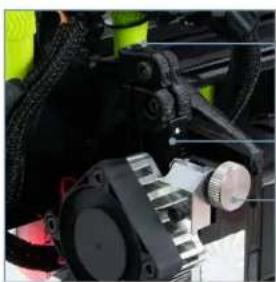
Close-up of mechanical components with no visible text or symbolsSK285 Tool Head Shown
Filament Path
Extruder Idler
Extruder Idler Adjustment Knob

natural_image
Close-up of a mechanical component with labeled parts, no visible text or symbolsSK285 Tool Head Shown
Blower Fan Shroud
Extruder Heater Cartridge
Extruder Heater Block
Extruder Nozzle
Bed leveling Sensor

natural_image
Abstract gray swirl design with no text or symbols03
Safety
3-1 Safety

\*CA Prop 65
WARNING: This product contains one or more chemicals known to the State of California to cause cancer and birth defects or other reproductive harm.
This warning is the result of a law passed in California in 1986 known as the California Safe Drinking Water and Toxic Enforcement Act of 1986, commonly referred to as "Proposition 65."
This warning does not mean that LulzBot products will necessarily cause cancer or reproductive harm. Furthermore, a Proposition 65 warning does not mean a product is in violation of any product-safety standards or requirements. To the contrary, the California government has clarified that "The fact that a product bears a Proposition 65 warning does not mean by itself that the product is unsafe." The California government has also explained, "You could think of Proposition 65 more as a 'right to know' law than a pure product safety law."
See http://oehha.ca.gov/prop65/background/p65plain.html
LulzBot 3D printers are not harmful when used as designed. We provide the warning as a result of this California law known as Proposition 65.


INJURY HAZARD
Warning: The 3D Printer includes moving parts that may cause injury. Take care to never put your fingers near any moving parts including belts, pulleys, or gears. Tie back long hair, clothing, or jewelry that can get caught in the moving parts of the printer.
Caution: When removing the print model from the Glass/PEI build surface, it may be necessary to carefully scrape the printed model off the surface of the build platform using a flat bladed putty knife. Try to reduce the angle between the putty knife and the PEI surface. Make sure that the blade of the putty knife is away from yourself and take care that your fingers and any part of your body are not in the direction of the blade. Note: Damage to print surface due to part removal is not covered under warranty.
BURN HAZARD
Warning: The 3D Printer generates high temperatures. Always allow the 3D Printer extruder and print surface to cool down before you touch them. The Hot End on the Tool Head can take up to 20 minutes to cool down completely. Extruded molten plastic can stick to your skin and cause severe burns.
Caution: The 3D Printer melts plastic during printing. Plastic odors and particles may be emitted during this operation. Make sure to set up the 3D Printer in a well-ventilated area.
Caution: Always allow the print surface to cool before removing a print. Additionally, always allow both the Hot End and print surface to cool before changing the Tool Head.
ELECTRIC SHOCK HAZARD
Warning: There is a risk of shock. Never open the electronics case when the printer is powered on. Before removing the electronics case cover, always power down the printer and completely unplug the printer. Allow the printer to discharge for one minute. Do not place the printer on carpet. Static discharge can damage components.
Caution: Power down the printer and allow the Tool Head to cool before disconnecting or connecting a Tool Head.
Caution: The socket outlet must be located near the printer and must be easily accessible.
Caution: In case of emergency, disconnect the 3D Printer from the socket outlet.
Safety 3-1

FIRE HAZARD
Warning: Never place flammable materials or liquids on or near the printer when it is in operation. Liquid acetone, alcohol, or other chemicals may release vapors that are extremely flammable.
Caution: Dust generation and accumulation should be minimized.

AGE WARNING
Caution: Children under 12 should be supervised by an adult over 18. Beware of choking hazards around small children.

MODIFICATION NOTICE
Warning: At LulzBot we respect your freedom to modify your LulzBot Desktop 3D Printer. However, any modifications or attempted repairs that cause damage are not covered under the LulzBot Limited Warranty.
Cloning LulzBot Products:
We publish our hardware designs and software packages under the GNU General Public License (GPLv3) and/or the Creative Commons (CC BY-SA 4.0). In non-legalese, this means that you are free to use, reproduce, sell, or modify our designs in any way you see fit, as long as you retain this same license for your projects using our work. For those wanting to use our hardware designs and/or software packages, we require you:
- Contact us with your intent to clone.
- Label the product as a LulzBot clone. It must be clear that it is not a product from our factory.
- Note that "LulzBot" is a registered trademark and requires permission for use.
Questions? Contact Customer Support by emailing Support@LulzBot.com.
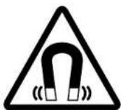
MAGNETIC HAZARD
Warning: To hold the Tool Head in position when the printer is off, the X Axis of the printer contains strong magnets which can be harmful to pacemaker wearers and others with medical implants. Keep tools and metal objects away. To avoid damage, keep magnetic memory media such as computer disks, credit cards, and tapes away from the magnets. Models equipped with the OctoGrab™ Magnetic Flexible bed also contain multiple strong magnets.
Safety 15
3-2 Safety

Follow all safety rules in this section and observe all cautions and warnings in this guide.
To ensure safety, please exercise caution when operating your SideKick.
POWER SUPPLY
The printer must be plugged into a power outlet that is close to the printer and easily accessible before use. Make sure that in an emergency, the power supply can be quickly shut off from the printer. Only use properly rated extension cords when necessary.
Before you plug your SideKick in for the first time, verify that the printer power supply is set to your correct AC line voltage. Check that the 110VAC or 240VAC switch is set to the correct voltage for your location.
If you have any questions about your power outlet, check with a qualified electrician.
OVERALL PROVISIONS
All information in this user manual ("Manual") is subject to change at any time without notice and is provided for convenience purposes only. LulzBot and our respective affiliates and suppliers ("LulzBot") reserves the right to modify or revise this Manual in its sole discretion and at any time and makes no commitment to provide any such changes, updates, enhancements, or other additions to this Manual in a timely manner or at all. Contact the LulzBot Customer Support Team for up-to-date information.
DISCLAIMERS
LulzBot does not warrant the accuracy or completeness of the information, products, or services provided by or through this Manual and assumes no responsibility for any typographical, technical, or other inaccuracies in this Manual, which is provided "as is" and without any express or implied warranties of any kind, including warranties of merchantability, fitness for a particular purpose, or non-infringement of intellectual property. In connection with your use of this Manual, LulzBot shall not be liable to you for any damages whatsoever, be they direct, economic, commercial, special, consequential, incidental, exemplary, or indirect damages, even if LulzBot has been advised of the possibility of such damages, including without limitation, loss of business revenue or earnings, lost data, or lost profits. LulzBot assumes no responsibility, nor will be liable, for any damages to, or any viruses or malware that may infect, your computer, telecommunication equipment, or other property caused by or arising from your downloading of any information or materials related to this Manual. The foregoing exclusions do not apply to the extent prohibited by law; please refer to your local laws for any such prohibitions. LulzBot makes no warranties to those defined as "consumers" in the Magnuson-Moss Warranty-Federal Trade Commission Improvement Act.
Safety 3-2
INTENDED USE
LulzBot 3D printers are designed and built for Fused Filament Fabrication. While we strive to create printers with the highest quality and dimensional accuracy, the end user remains responsible to validate the application of printed objects for intended use. Critical applications in regulated fields such as aeronautics and medical devices should give extra care to qualify the end use of printed parts.
THIRD-PARTY MATERIALS
The LulzBot Open Filament System allows users to choose the material that best fits their application. Print profiles for LulzBot tested materials are pre-loaded into Cura LE. LulzBot makes every effort to support the materials listed in Cura LE and materials customers purchase at www.LulzBot.com.
Third-party manufacturers of material not sold on LulzBot.com or without profiles included in Cura LE can contribute appropriate print profiles and safety data sheets to the user for each specific material they manufacture. LulzBot cannot be responsible for any adverse effects from the use or performance of these third-party materials.
Material issues or resulting Tool Head damage are not covered by LulzBot customer support or your Warranty. Material questions and concerns should be directed to the material manufacturer.
SOURCE FILES
This product runs with free software because we support your right to see how it works, make modifications, and share your modifications with others. Find the source files online at gitlab.com/lulzbot3d. See the Technical Specifications section in Chapter 12, for more information on open source hardware.

natural_image
Abstract gray swirl design with no text or symbols04
Simple Set Up Guide
4-1 Simple Set Up Guide

Experienced users can use this Simple Set Up Guide to walk through 10 easy steps to prepare the TAZ SideKick for printing.
Every step includes a reference to the chapter in this PDF User Guide that contains more detailed instructions on each process.
New users can find more detailed instructions beginning in Chapter 5, Unpacking.
If you don't find the answers in this User Guide, contact LulzBot support at Support@LulzBot.com to talk to a friendly LulzBot Customer Support Team Member.

Unpack - Remove your SideKick from the packaging material and remove all of the orange shipping fasteners from the printer. For more details, see Chapter 5, Unpacking.
natural_image
Close-up of hands installing or adjusting a device component with visible internal components (no text or symbols)
Assembly - Mount the Y-Axis to the printer frame. Swing out and secure the electronics enclosure and gLCD control panel (if equipped) and mount the Tool Head (if equipped). Open the spool mount and connect the filament guide tube. For more details, see Chapter 7, Assembly.

natural_image
3D-printed LULZOOT robotic device with articulated arms and a small display panel (no visible text or symbols)
Slicer Installation - Install Cura LulzBot Edition (LE) on your desktop computer following the installation prompts. Cura LE is included on the SD card that came with your SideKick. The most current version of Cura LE can be downloaded from www.LulzBot.com/cura. For more details, see Chapter 8, Slicer Installation & Set Up

Simple Set Up Guide 4-1
4-104 Add Printer - Launch Cura LE. Go to Settings>Printer>Add Printer. Select the LulzBot TAZ SideKick model and select the Tool Head installed on your printer. Click Add Printer. Click Finish on the next menu. Cura LE is now ready for use with your LulzBot TAZ SideKick. For more details, see Chapter 8, Slicer Installation & Set Up

4-1.05 Load File to Print - Load your first file from the included SD card. Select Open File in Cura LE and choose OctopusRev06.stl from the included SD card. In the Prepare sidebar in Cura LE, confirm that PolyLite PLA is selected for material and Standard is selected. For more details, see Chapter 8, Slicer Installation & Set Up.

natural_image
3D modeling software interface showing a wireframe model of a green gemstone on a white base, with no visible text or symbols.4-1.06 Connect Printer - Plug the USB cable into your computer and the top of the electronics enclosure on the back of the printer. Plug in the AC power cable at the back of the printer and plug it in to an AC outlet. Turn the printer on using the red power switch on the lower right front of the printer. For more details, see Chapter 9, Preparing SideKick to Print

natural_image
Close-up of a hand holding a black 3D printer with attached cable, no visible text or symbols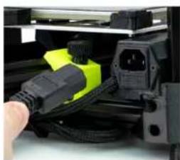
natural_image
Close-up of a black electronic device with a yellow connector being inserted, showing wiring and ports (no visible text or symbols)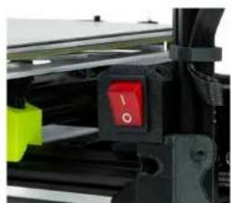
natural_image
Close-up of a black mechanical device with a red indicator light and yellow tag (no visible text or symbols)4-1 Simple Set Up Guide
4-107 Load Filament - Load the included PLA sample of filament. Ensure the filament is the correct diameter (1.75mm or 2.85mm) for the Tool Head you have installed on your SideKick. For more details, see Chapter 9, Preparing SideKick to Print

natural_image
Close-up of a hand holding a black mechanical device with green and yellow components (no visible text or symbols)
Adjusting Z-offset WITHOUT the gLCD Controller:
Your LulzBot SideKick 3D printer has the ability to change the first layer height (Z offset) directly through Cura. From the Monitor tab, click Console. In the lower right hand corner of the Printer Control Window in Cura, enter the following commands, then click Send Command. (The green text explains the command, do not enter it.)
• M851 Reports your current Z offset
• M851 ZXXX Updates your Z-offset to XXX
• M500 Save new offset
To decrease the Z-offset between your nozzle tip and the print surface (decreasing the gap,) subtract from your current offset when changing XXX. To increase the Z-offset between the nozzle tip and the print surface (increasing the gap,) add to your current offset when changing XXX. When updating your offset, be sure to make small changes between prints.
We recommend making changes using small, 0.1 mm increments at a time.
22 Simple Set Up Guide
4-108 Start Print - In Cura LE, click the Monitor button. Click Connect. Click Start Print. Your TAZ SideKick will automatically prepare itself for 3D printing. For more details, see Chapter 10, Starting Your First Print.

natural_image
3D CAD model of a mechanical part with a green gemstone on a base, displayed in a design software interface (no text or symbols on the model itself)4-109 Check Level and Z-offset - Before each print, your SideKick will conduct a bed-leveling sequence. Using the gLCD controller (if equipped). Go to Configuration>Advanced Settings>Z Offset. Adjust the Z-offset to achieve optimum bed adhesion. For more details, see Chapter 10, Starting Your First Print.
The default Z-offset is -0.62

natural_image
Close-up of a yellow 3D-printed device with a glowing octopus-shaped component on a grid floor, no visible text or symbols.Simple Set Up Guide 4-1
4-1.10
Print Part - Your SideKick will now print your part. When the part is complete, the printer will move the bed to rear the of the machine to cool. Once the print bed is cool, it will move the print bed to the front. You can then remove your print. For more details, see Chapter 10, Starting Your First Print.

natural_image
Yellow octopus-shaped object with five legs, enclosed in a green hexagon on a tiled surface (no text or symbols)
natural_image
Abstract gray swirl design with no text or symbols05
Unpacking
5-1 Unpacking

RETAIN ALL PACKING MATERIALS.
In the event that warranty service is needed, the SideKick 3D printer MUST be shipped in its original packaging to ensure safe delivery. Keep ALL packing materials that came with your SideKick. The orange shipping fasteners, packing foam, and box.
Shipping the printer without using the original packaging can result in damage to the printer that is not covered by the warranty, see Chapter 15, Warranty & Support.

natural_image
3D rendered black mechanical component with internal structural framework (no text or symbols)

With the box on a sturdy surface, carefully open the top of the box marked "OPEN HERE".


Remove the accessory bags from the packing material and set aside for later use.

natural_image
Open cardboard box containing various electronic components and a green ring, no visible text or symbols.
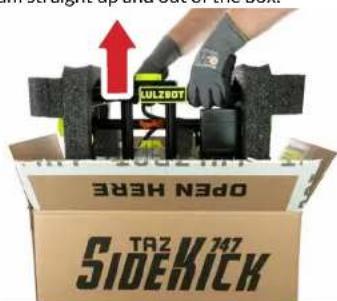
Firmly grasp the printer frame and lift the printer and packing foam straight up and out of the box. This may require two people.
Unpacking 5-1
5-104 Set the printer and packing foam upright on a sturdy surface.

natural_image
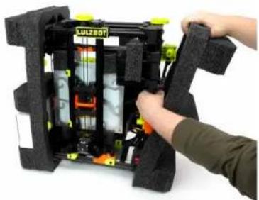
Interior view of a mechanical or electronic device with visible components and mounting brackets (no readable text or symbols)5-1.05 Remove the accessory box from the lower foam pocket and set aside for later use. While supporting the printer frame with one hand, pull the packing foam from all sides of the printer.
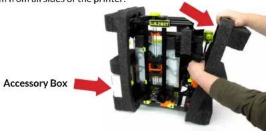
5-106 Set the unpacked printer upright on a sturdy surface. You are now ready to begin the quick process of assembling your SideKick!

natural_image
Interior view of a black industrial machine with yellow safety tags and internal components (no visible text or symbols)
IF YOUR SIDEKICK IS DAMAGED OR IS NOT WORKING PROPERLY, DO NOT RETURN TO THE STORE OR RETAILER.
If you have an issue with your printer or with the performance of this product please contact LulzBot at:
Web: www.LulzBot.com/Support Email: Support@LulzBot.com Phone: +1-701-809-0800

Before beginning the assembly process, take a moment to familiarize yourself with the key components of your new SideKick 3D printer in Chapter 2, Meet Your SideKick.

In Chapter 6, What's in the Box? We will verify all the items you unpacked.

natural_image
Abstract gray swirl design with no text or symbols06
What's in the Box?
6-1 Printer & Y-Axis
SideKick Printer Frame

natural_image
3D-printed LULZBOT robotic frame with black frame, yellow control knobs, and orange actuators (no visible text or symbols)SideKick Y-Axis Carriage

30 What's In The Box?
Standard & Optional Items 6-1
Standard Items
Filament Guide Tube

natural_image
Black power cord with attached plug, labeled 'Power Cord' (no other text or symbols)
USB Cable
SD Card

natural_image
Yellow circular object with a red card labeled 'i-Verkurs' and a small label, no readable text or symbols on the object itself.Filament Sample
Allen Key Set (13pc)

Small Items Bag

Optional Items
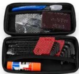
Deluxe Tool Kit (optional)
natural_image
Open black-and-white photo of a medical kit case with tools and a blue mesh cover (no visible text or symbols)Contents of Deluxe Tool Kit

natural_image
Assorted tools and materials including pliers, scissors, and a paintbrush (no visible text or labels)Filament Runout Sensor (optional)

natural_image
Close-up of a black plastic electrical connector with a cable (no visible text or symbols)
NOTE: Due to the customizable nature of the SideKick 3D printer, the appearance of some components in this user guide may vary from your customized configuration.

natural_image
Abstract gray swirl design with no text or symbols07
Assembly
7-1 Electronics Enclosure Assembly

NOTE: The color and appearance of some components may vary depending on the configuration of your SideKick.

Do NOT force the enclosure beyond 90° or you may damage the mounting hinge.

Locate the clips on the electronics enclosure at the back of the printer. Lift the retaining clips to free the enclosure. Rotate the electronics enclosure 90° until it rests on the support bracket.


Once the electronics enclosure is in place, secure it by replacing the two retaining clips.


NOTE: Depending on the configuration you selected, your SideKick may not be equipped with a gLCD controller.

Do NOT force the gLCD controller beyond the backstop, you may damage the mounting hinge.

Rotate the gLCD controller (if equipped) out of the frame and to the right until it rests on the adjustable back stop.

natural_image
Close-up of a black mechanical component with a red circle highlighting a specific area, no visible text or symbols.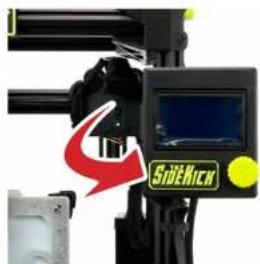

natural_image
Close-up of a black mechanical device with yellow connectors and a red arrow pointing to a component (no visible text or symbols)34 Assembly
Y-Axis Assembly 7-2
7-2.01 Locate and remove the four (4) thumbscrews on the bottom front side of the printer. Turn these counterclockwise to remove. Retain these for use in steps 7-2.06 and 7-2.07.

natural_image
3D printer assembly view showing internal components and a red circular annotation (no readable text or symbols)7-2.02 Holding the Y-Axis assembly at the top, slide it straight up a couple inches, then lower it at a slight angle while slightly rotating it to remove it from the printer. Two (2) orange spacer rings should be removed from the bottom Y-axis mount.

natural_image
Two 3D printer models with green and red arrows indicating process flow, no visible text or symbols on the devices themselves.7-2.03 Gently place the Y-Axis assembly face down on a soft, clean surface. Remove the orange shipping bracket on the bottom of the Y-Axis assembly by pulling it up and away from the assembly.

natural_image
Person assembling a mechanical assembly with a red component on a black frame (no visible text or symbols)
Take care to not damage the printer or Y-Axis during this process
7-2 Y-Axis Assembly

Save all the orange shipping fasteners with the other packaging materials!
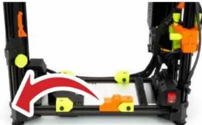
7-204 Locate and remove the orange shipping block on the front bottom rail of the frame. Slide to the left and pull the block up and away from the extrusion.
natural_image
3D printer assembly with orange and yellow components, showing a red arrow indicating motion (no text or symbols)
Do not over-tighten the Y-Axis thumbscrews. Damage to the Y-Axis mounting bracket can occur.
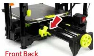
7-2.05 Locate the small bag containing four (4) Y-Axis clamps and one (1) black connector retaining clip. Set the retaining clip aside for use in step 7-2.10. Two (2) of the Y-Axis clamps and two (2) thumbscrews (from step 7-2.01) should be placed on front and back left frame mounting brackets as shown with the holes aligned and the angled side facing the center of the printer. Tighten the thumbscrews clockwise. At this point, don't fully tighten the Y-Axis clamps. Leave them loose.

7-2.06 Attach the Y-Axis assembly to the printer frame with the belt tension knob facing forward and the print bed facing upward. Align the Y-Axis mounting guides with the left Y-Axis frame rail using the two Y-Axis clamps you installed in step 7-2.05. The rear mounting guide aligns with the back of the rear clamp, while the front mounting guide aligns with the front clamp.
natural_image
3D printer front view with yellow wheels and a red arrow indicating a component (no text or symbols on the device itself)
natural_image
Close-up of a 3D printer with black frame and green clamps, showing mechanical components and a red arrow indicating motion (no text or symbols)Y-Axis Assembly 7-2
7-2.07 Manually slide the print bed to the front. Place one (1) thumbscrew you removed in step 7-2.01 and one (1) Y-Axis clamp from the small bag on the right rear frame mounting bracket. Place the Y-Axis clamps with the holes aligned and the angled side facing the center of the printer. Tighten both the rear thumbscrews by turning both clockwise and then finger tight.

natural_image
3D printer with LULBOT branding and red arrows indicating motion or movement (no readable text beyond branding)7-2.08 Manually slide the print bed to the back. Place one (1) thumbscrew you removed in step 7-2.01 and one (1) Y-Axis clamp from the small bag on the right front frame mounting bracket. Place the Y-Axis clamps with the holes aligned and the angled side facing the center of the printer. Tighten both the front thumbscrews by turning both clockwise and then finger tight.

natural_image
Close-up of a 3D printer with red arrows indicating motion or movement, showing no visible text or symbols on the device itself.7-2 Y-Axis Assembly
7-2.09 Locate the wire harness coming from the back of the electronics enclosure. Securely plug the small connector and large heater bed connector into to the print bed connection at the back of the print bed.

natural_image
Close-up of a hand holding a small electronic component with a red arrow pointing to it, next to a grid-patterned surface (no text or symbols visible)7-2.10 Locate the small black power clip in the small bag. Insert the two posts on the retaining clip into the two holes on top of the print bed connector.

Secure electrical connections are important. Ensure that the connector is seated firmly and that you use the connector clip to lock the connection.

natural_image
Close-up of hands installing a component on a car chassis with a grid pattern (no visible text or symbols)7-21 Locate the Y-Axis stepper motor connector at the back of the Y-Axis assembly. Plug the Y-Axis stepper motor connector into the stepper motor and slide the flexible cover over it to protect the connection.

natural_image
Close-up of a 3D printer with black frame and yellow clamps, no visible text or symbols
natural_image
Close-up of a mechanical component with a red circle highlighting a specific area, showing no visible text or symbols.Tool Head Assembly 7-3
7-3.01 If you configured your SideKick with a Tool Head, look for the orange shipping fastener on the right side of the printer frame. As you support the Tool Head, turn the two (2) top thumbscrews counterclockwise. Remove the Tool Head, the two (2) thumbscrews and set aside for later use in step 7-3.05 and 7-3.06.

natural_image
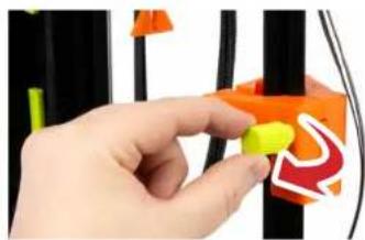
Close-up of a hand holding a yellow and green mechanical device with orange components (no visible text or symbols)7-3.02 The orange Tool Head mount has a green thumbscrew on the side that must be turned counterclockwise to remove it. Set the thumbscrew aside for use in step 7-3.07. Remove all orange Tool Head shipping parts from the frame, taking care not to damage the gLCD wires (if equipped).
natural_image
Hand placing a yellow object into an orange and red abstract shape against black vertical lines (no text or symbols visible)7-3.03 Before continuing, take the orange belt clips off the X and Z-Axis and remove the orange cover from the BL Touch on the bottom of the X-Axis carriage. Make sure ALL orange shipping fasteners are removed from the 3D printer before proceeding to the next step.

natural_image
Close-up of a hand holding an orange tool next to a black 3D printer (no text or symbols visible)
NOTE: The actual Tool Head on your printer may vary from the one pictured in the instructions, depending on the configuration of your SideKick.
Because of the unique LulzBot Universal Mounting System, these instructions will be the same for any of the Tool Heads selected with the SideKick.
More information on Tool Heads can be found in Chapter 11, Tool Heads & Accessories.

VERIFY THAT ALL ORANGE SHIPPING FASTENERS HAVE BEEN REMOVED FROM THE PRINTER BEFORE CONTINUING.
Save all of the orange shipping fasteners with the other packaging materials!

Assembly
7-3 Tool Head Assembly

VERIFY THAT ALL ORANGE SHIPPING FASTENERS HAVE BEEN REMOVED FROM THE PRINTER BEFORE CONTINUING.
Save all of the orange shipping fasteners with the other packaging materials!

natural_image
Abstract orange geometric shapes on white background, no text or symbols present
Locate the Tool Head mount on the X-Axis at the top right of the 3D printer. Slide the Tool Head mount to the center of the X-Axis gantry.

natural_image
Hand holding a black mechanical component with a red arrow pointing to a component (no visible text or symbols)
Line up the Tool Head on the X-Axis mount.

natural_image
Close-up of a hand holding a black mechanical device with green and red directional arrows indicating motion (no text or symbols visible)
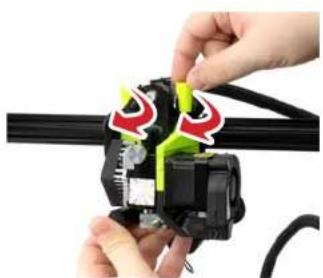
Using one hand to support the Tool Head, insert the two short thumbscrews from step 7-3.01 into the top of the Tool Head and turn clockwise until finger tight.
natural_image
Close-up of hands installing a mechanical component with red and green markings (no visible text or symbols)Tool Head Assembly 7-3
7-3.07 Locate the long Tool Head Mount thumbscrew from step 7-3.02. There is a small hole in the back of the Tool Head Mount above the BLTouch. Insert the screw into the hole and turn clockwise until finger tight.

natural_image
Close-up of two hands installing a mechanical component with wires and a yellow-green knob, showing a red arrow indicating motion (no text or symbols present)7-3.08 With the printer power switch in the OFF position, locate the Tool Head wiring harness and Tool Head mount connector at the top of the Tool Head. Plug the Tool Head wiring harness into the Tool Head mount connector. Slip the black flexible loop over the post of the nearest thumbscrew.

natural_image
Close-up of hands connecting a black cable to a green robotic device, showing red directional arrows (no text or symbols)7-3.09 With the Tool Head securely mounted and the connector fastened, your SideKick is almost ready to start printing!

natural_image
Close-up of a black LULZBOT robotic arm with visible wiring and mechanical components (no text or symbols)7-4 Spool Mount Assembly
7-4.01 Locate the built in spool mount on the left side of the printer frame.

natural_image
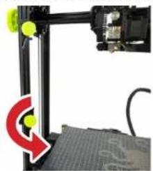
Mechanical assembly with green and yellow components, no visible text or symbols7-4.02 Loosen the thumbscrew by turning it counterclockwise - DO NOT remove it. Rotate the arm down 90°. Retighten the thumbscrew by turning clockwise.
natural_image
Close-up of a mechanical assembly with a red curved arrow pointing to a green circular component (no text or symbols visible)
natural_image
Close-up of a mechanical clamp or bracket with green and yellow components, showing a red arrow indicating motion (no text or symbols visible)
natural_image
Close-up of a mechanical clamp or bracket with yellow components and a red curved arrow indicating motion (no text or symbols)
Do not force the spool arm back beyond it's 5° of free movement or damage may occur.
7-4.03 The arm has approximately 5° of movement front to back to accommodate different sizes of material spools without interfering in the print area. Adjust to your preference.

natural_image
Close-up of a 3D printer assembly with green and black components, no visible text or symbols42 Assembly
Guide Tube Assembly 7-5
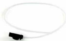
7-5.01 Obtain the clear filament guide tube from the accessory bag you removed from the printer packaging earlier. Your SideKick should have the correct diameter guide tube for the Tool Head you selected.
natural_image
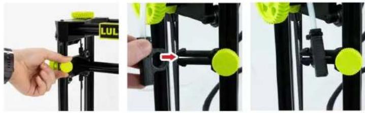
Simple line drawing of a black connector attached to a white cable (no text or symbols)7-5.02 Locate the built in guide tube holder on the left side of the printer frame (above the Spool Mount). Loosen the thumbscrew by turning it counterclockwise - DO NOT remove it. Rotate the guide tube holder down 90°. Retighten the thumbscrew by turning clockwise. Attach the filament guide tube to the guide tube holder.
natural_image
Three-panel image showing a hand adjusting a green LUL component on a black frame, with no visible text or symbols.7-5.03 Locate the free end of the filament guide tube and run it over the top of the 3D printer, placing it near the Tool Head on your SideKick. Do not insert it into the Tool Head yet. We will finish installing this in a later step.

natural_image
Close-up of mechanical components with no visible text or symbols
The filament guide tube is a critical part of the Tool Head assembly. Failure to install the filament guide tube can have a detrimental effect on print quality.
See Chapter 14, Troubleshooting, Lines on side of print.

If your SideKick is equipped with the optional Filament Runout Sensor more information can be found in Chapter 11, Tool Heads & Accessories.

Set your SideKick aside and grab your computer. For the next step in Chapter 8, Slicer Installation & Set Up, we will take a few moments to install and set up Cura LE before starting your first print.
Assembly

natural_image
Abstract gray swirl design with no text or symbols08
Slicer Installation & Set Up
8-1 Slicer Installation

A slicer is a computer program that takes a three-dimensional model (typically STL/OBJ/etc) and determines the 3D printer tool-path based on the options selected. The slicing engine uses the nozzle diameter, movement speeds, layer height, and other variables to determine the coordinates where it needs to move, and the rates at which it will do so. This information is exported out of the program as a plain-text .gcode file and loaded to the printer.
There are several slicers available, but we recommend that new users start with Cura LulzBot Edition for their first SideKick printing experience.

The LulzBot TAZ SideKick is compatible with Cura LulzBot Edition version 3.6.25 and later. If you have an older version of Cura LulzBot Edition installed, you will need to download the latest version at www.LulzBot.com/Cura in order to use your LulzBot TAZ SideKick.
There may be later versions of Cura LulzBot Edition available with added features and functionality. We recommend checking for updates regularly.

Cura LulzBot Edition is the recommended software to control your LulzBot TAZ SideKick. It includes built-in support for compatible materials optimized for use with the TAZ SideKick. Find installation instructions, troubleshooting information, and more at www.LulzBot.com/Cura.
Already have Cura LulzBot Edition? Update now to get additional material support and new slicing profiles. Expert help and advice is available at www.LulzBot.com/Support.

Launch Cura LulzBot Edition. The Add Printer menu will automatically appear. Select the correct LulzBot TAZ SideKick model and select the Tool Head installed on your printer, then click Add Printer. Existing users should select the Settings drop-down menu, Printer, then Add Printer. On the next menu that appears, click Finish to complete the printer setup. Cura LulzBot Edition is now ready for use with your LulzBot TAZ SideKick.


New firmware is continuously being developed to add new functionality and ensure your LulzBot TAZ SideKick is creating the best quality prints. With the printer powered on, the USB cable connected between your printer and a computer with Cura LulzBot Edition installed, update the printer firmware by clicking the Settings drop-down menu and selecting Printer, then Manage Printers. With LulzBot TAZ SideKick highlighted, click Upgrade Firmware and follow the prompts to install the latest firmware.
Slicer Installation 8-1
B-1.04 The first print model, OctopusRev06.stl, will automatically load onto Cura LulzBot Edition's virtual print bed the first time you run Cura LulzBot Edition with your LulzBot TAZ SideKick.
8-1.05 In the Prepare sidebar on the right side of the screen, confirm that PolyLite PLA (Polymaker) is selected for Material and Standard is selected for the Profile to be used for printing.
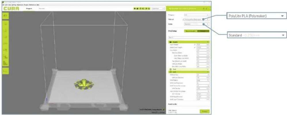

If the first print model is not present in the virtual print bed, you can download it from https://gitlab.com/lulzbot3d/printers/taz-sidekick/-/tree/master/sample_prints/Octopus or from the included SD card, and then load it onto the virtual print bed using the Open File button in the main Cura interface.

Filament is the term for the materials your LulzBot TAZ SideKick uses to 3D print objects. The included sample filament, PLA, is made from natural renewable resources. PLA and other types of filament can be purchased at www.LulzBot.com/filament.

Now that you have Cura LE installed, we will move on to the next step in Chapter 9, Preparing SideKick to Print in which we power on and load filament in your SideKick to prepare for the first print.
Slicer Installation & Set Up 47
Attribution: The OctopusRev06 model by Aleph Objects, Inc is licensed under CC BY-SA 4.0 and derived from work by yeoldebrian.

natural_image
Abstract gray swirl design with no text or symbols09
Preparing SideKick to Print
9-1 Preparing to Print

During the printer startup cycle, the X-axis will move to the top of the frame and make contact with the left and right stops in order to level the X-axis. Make sure the print area is free of obstructions. This process also completes before each print.

Verify that the power switch on the front of the TAZ SideKick is in the OFF position.

natural_image
Close-up of a mechanical control panel with a red indicator light and black components (no visible text or symbols)
Plug in the included USB cable, connecting the TAZ SideKick to a computer.

natural_image
Close-up of a hand holding a black 3D printer cable with a gold connector (no visible text or symbols)
Verify that the power supply is set to your correct AC line voltage before you plug your SideKick in for the first time. Check that the 110VAC or 240VAC switch is set to the correct voltage.

Plug in the AC power cord.

natural_image
Close-up of a mechanical assembly with yellow and black components, no visible text or symbols
Flip the red power switch to the ON position to turn on the TAZ SideKick. (Switch will illuminate red when powered on.)

natural_image
Close-up of a red toggle switch with '1' and '0' labels, mounted on a black mechanical component (no readable text or symbols beyond the labels)Preparing to Print 9-1
9-1.05 Your TAZ SideKick will now power on. Printers equipped with the gLCD screen will start up with the LulzBot and Marlin splash screens before the Home Screen as the printer prepares itself to operate.
9-1.06a Changing Filament WITH the gLCD Controller:
Press in on the gLCD Control Knob to access the main menu on the gLCD Controller. Turn the knob clockwise to scroll down to Change Filament and then press in on the gLCD Control Knob to select. In the next menu, scroll to select Change Filament. In the next menu, scroll to select Preheat PLA and press the gLCD Control Knob to select. The screen will display Print Paused, then Filament Change. Follow the screen prompts to complete the filament change process.

flowchart
graph LR
    A["Motion"] --> B["Main"]
    B --> C["Change Filament"]
    C --> D["Load Filament"]
    D --> E["Unload Filament"]
    E --> F["Preheat FLA"]
    F --> G["Preheat ABS"]
    G --> H["Preheat Customs"]
    H --> I["PIFLMENT CHANGE"]
    I --> J["Hozzle heating"]
    J --> K["Please wait..."]
    K --> L["Hoseler: 11.5/190"]
9-1.06b Changing Filament WITHOUT the gLCD Controller:
From Cura LE, click on the Monitor button at the top of the main Cura interface. This will change the sidebar on the right side of the screen to show printer information and controls.

Click the Connect button under Manual Control to connect to the LulzBot TAZ SideKick. Once connected, the top status bar will change from USB device available to Connected via USB and the current hot end and print bed temperatures will be displayed in Cura LE.

flowchart
graph LR
    A["Select transformer"] --> B["Extrusion amount: 5"]
    C["Select temperature: 200"] --> D["Heat bed"]
    E["Select transformer"] --> F["Extrusion amount: 1"]
    G["Select temperature: 200"] --> H["Heat bed"]
    I["Select transformer"] --> J["Extrusion amount: 1"]
    K["Select temperature: 200"] --> L["Heat bed"]
    M["Extrusion amount: 1"] --> N["Exit"]
    O["Exit"] --> P["Exit"]
Enter 190 (for Polylite PLA) into the Select Temperature field and click Heat Extruder to raise the hot end temperature to 190^ C. Once the printer has reached temperature, you can remove any remaining filament by clicking the Retract button several times to back the filament out of the Tool Head.

Your LulzBot TAZ SideKick was tested for quality assurance before being packaged. You will need to remove the remaining filament left in the tool head from this process before loading new filament for your next print. Follow these steps below to remove or change the filament.
9-1 Preparing to Print

HOT SURFACE BURN HAZARD. CONTACT MAY CAUSE BURNS. DO NOT TOUCH THE HOT END.
The hot end on the extruder is now heating up to 190°C (374°F) and can burn your skin if you touch it.
9-1.07
Once the hot end reaches the target filament removal temperature, the filament will automatically begin to retract. Once the filament stops moving, pinch the idler and pull out the remaining filament strand.

natural_image
Close-up of a 3D printer's internal components with black and green parts, no visible text or symbols
natural_image
Close-up of a mechanical assembly with visible components and wiring (no text or symbols)

The filament holder may need to be adjusted to accommodate larger spools of filament. Loosen the thumbscrew (without removing it) and move the filament holder arm into the appropriate position and re-tighten the thumbscrew.
9-1.08
Locate the included sample coil of filament from the accessory bag that came with your printer. We strongly recommend using the included PLA sample filament for your first print.
9-1.09
Feed the included PLA sample filament into and through the filament guide tube. Continue pushing the filament by hand completely through the guide tube until it exits at the filament guide tube holder near the top of the extruder.

If your SideKick is equipped with the optional Filament Runout Sensor you can find more information in Chapter 11, Tool Heads & Accessories. The optional Filament Runout Sensor replaces the base of the Filament Guide Tube.

natural_image
Close-up of a robotic arm with green and red directional arrows indicating movement or force (no text or symbols visible)52 Preparing SideKick to Print
Preparing to Print 9-1
9-1.10
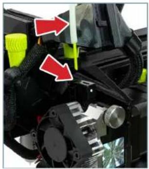
Locate the filament guide tube holder and extruder idler on the tool head where the loaded filament was removed during step 9-1.07. Filament feeds down this path and into the hot end for printing.
SK175, SK285, SE, HE, SL, HS and HS+ Tool Heads
H175 Tool Head M175 Tool Head
natural_image
Close-up of a mechanical component with red arrows pointing to features, no visible text or symbols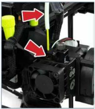
natural_image
Close-up of a mechanical device with red arrows pointing to components, no visible text or symbols
natural_image
Close-up of a Bono Tech. robotic device with red arrows indicating motion or force directions (no readable text or symbols)9-1.11
Straighten the filament slightly and while pinching the filament guide tube holder/Extruder idler, feed the filament into the extruder. The idler may need to be loosened for filament to be inserted properly. Once the filament is in place, adjust the idler to the ideal tension shown in step 9-2.01 a, 9-2.01 b or 9-2.01 c (depending on Tool Head model).
SK175, SK285, SE, HE, SL, HS and HS+ Tool Heads H175 Tool Head M175 Tool Head

natural_image
Close-up of a hand holding a black mechanical component with a red circle highlighting a specific part (no text or symbols visible)
natural_image
Close-up of a hand using a screwdriver to adjust a CPU socket (no text or symbols visible)
natural_image
Close-up of a hand adjusting a BOND TESH device component with a red circle highlighting a small component (no text or symbols visible)
Make sure you have the correct diameter filament for the Tool Head you have selected.

The hot end is still heated to 190°C (374°F) and can burn your skin.

The filament must be inserted past the extruder hob gear in the Tool Head for filament to extrude properly. If there is resistance while pushing filament through the idler, trimming the filament at a 45° angle may help.


More information on Tool Heads can be found in Chapter 11, Tool Heads & Accessories.
9-1 Preparing to Print

Regardless of style of Tool Head you have installed, having the idler tension too loose or too tight will cause issues with print quality and potentially cause jamming in the extruder.

After removing filament, a small residual amount remains in the hot end that needs to be cleared out through the process of purging as detailed above. This purging process helps to remove any residual material left in the hot end.

Now that you have filament loaded, we will move on to the next step in Chapter 10, Starting Your First Print.
54 Preparing SideKick to Print
9-1.12a Purge/Advance Filament WITH the gLCD Controller:
With the PLA in place, press the gLCD control knob to begin the purging process. Let the filament advance until it extrudes smoothly as shown. If the filament stops advancing and filament is not extruding from the nozzle, select Purge More, otherwise select Continue to return to the Main Menu.

9-1/2b Purge/Advance Filament WITHOUT the gLCD Controller:
From Cura LE, click on the Monitor button at the top of the main Cura interface. This will change the sidebar on the right side of the screen to show printer information and controls.

Click the Connect button under Manual Control to connect to the LulzBot TAZ SideKick. Once connected, the top status bar will change from USB device available to Connected via USB and the current hot end and print bed temperatures will be displayed in Cura LE.

Enter 190 (for Polylite PLA) into the Select Temperature field and click Heat Extruder to raise the hot end temperature to 190^ C. Once the printer has reached temperature, load new filament and click the Extrude button a few times to purge any leftover filament. Repeat as needed until you see consistent and repeatable extrusion. Now you are ready to print. If you need to make any further adjustments to your model or profile settings, you will need to navigate back to the Print Setup button at the top-right corner of the screen.

Return to the Main Menu. Scroll down and select Temperature. Once in the Temperature menu, scroll to select Cool down.
Tool Head Tension 9-2
9-20a Tension setting guide for LulzBot Titan Aero based Tool Heads. (SK175, SK285, SE, HE, SL, HS and HS+)

Clockwise - Loosen

Counterclockwise - Tighten

9-20b Tension setting guide for LulzBot M175 Tool Head. 1. Turn the Idler Adjustment Knob clockwise until finger-tight. 2. Turn counterclockwise 1-2 full turns for PLA and other hard filament. 3-4 full turns for NinjaFlex, Nylon, and other flexible filament.

1. Clockwise - Until Finger Tight.
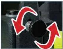
2. Counterclockwise - 1-4 full turns depending on filament being printed.
9-2.01c Tension setting guide for the H175 Tool Head. The idler tension can be set to nominal (see photo below) for the most common filament types including PLA, PETG, ABS, ASA, PC, and HIPS. With harder filament, you may need to tighten the idler tension. NinjaFlex, Nylon, and other flexible filament may require tension to be decreased.

Clockwise - Tighten
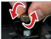
Counterclockwise - Loosen

Nominal tension setting.

During printing, the extruder idler holds filament against the extruder hob gear which pushes filament down into the hot end. Correct idler tension is important for to keep filament flowing properly during the printing process.
9-201 a - On Titan Aero based LuizBot Tool Heads, the idler tension can be seen by looking at the tool head from above. Rotating the idler adjustment knob CLOCKWISE will LOOSEN the idler. Rotating the idler adjustment knob COUNTERCLOCKWISE will TIGHTEN the idler.
9-2.01 b - On the M175 Tool Head, rotating the idler adjustment knob CLOCKWISE will TIGHTEN the idler. Rotating the idler adjustment knob COUNTERCLOCKWISE will LOOSEN the idler.
9-1.01 c - On the H175 Tool Head, rotating the idler adjustment knob CLOCKWISE will TIGHTEN the idler. Rotating the idler adjustment knob COUNTERCLOCKWISE will LOOSEN the idler.

Do not force the filament tension knob tight. Using excessive force will damage the laser sintered nylon that holds the metal insert in place.
Preparing SideKick to Print

natural_image
Abstract gray swirl design with no text or symbols10
Starting Your First Print
10-1 Starting Your First Print

If you need to make changes to your model, use the Prepare sidebar at the top left corner of Cura. Once changes are made, Cura will automatically begin implementing the changes, also known as re-slicing.

The X-Axis gantry may shift after your 3D printer is powered off. Every time the LulzBot TAZ SideKick powers on, it will attempt to auto-home. Verify that the X-axis and print bed are clear before turning your machine on. Failure to do so could result in damage to the printer or other equipment.

Your LulzBot TAZ SideKick can be operated without a USB tether to a computer IF EQUIPPED with the gLCD and included SD card. Once models are sliced and a .gcode file is saved they may also be saved to the included SD card by clicking Save to Removable Drive in the lower right corner of Cura. Once saved, models may be printed directly from the SD card by plugging it into the slot located on the left side of the gLCD, selecting Print from Media in the Main Menu, and selecting the model you would like to print.

Your 3D printer is now ready to print! Click on the Monitor button at the top of the main Cura interface. This will change the sidebar on the right side of the screen to show printer information and controls.


Before starting a print, check that your printer is ready. The hot end is still hot, use caution:
- Confirm that all packaging and orange clips have been removed from your LulzBot TAZ SideKick.
- Verify that the 3D printer is in a well-ventilated area, on a flat and level surface, and has 30cm (12in) clearance in all directions.
Starting Your First Print 10-1
10-1.02 Click the Connect button under Manual Control to connect to the LulzBot TAZ SideKick.
10-LO3 Once connected, the top status bar will change from USB device available to Connected via USB and the current hot end and print bed temperatures will be displayed.
10-1.04 Click Start Print at the bottom of the Monitor sidebar to start your first 3D print.

10-1.05 Your 3D printer will first move the tool head to the bottom left corner of the build area. The Tool Head nozzle and build plate surface will begin heating to the temperatures that are set in Cura. The printer will start a multiple point probing sequence to get an accurate mesh map of the build plate surface.
289 Models - 9-point probing
747 Models - 16-point probing

natural_image
Close-up of a red laser beam interacting with a black surface, no visible text or symbols
*Always watch your LulzBot TAZ SideKick start the printing process to visually ensure proper functionality. Always monitor that the material is adhering to the print bed and the printer is functioning normally before allowing the printer to continue printing. Printers should not be left unattended while printing.

There is a small length of PLA filament remaining in the hot end after your first sample print. You can remove the remaining filament by following the steps in Chapter 9, Preparing to Print.
Use this process whenever changing the filament to ensure a clean switch between different filaments and to avoid extrusion issues due to print temperature differences.
When using a filament other than PLA for future prints, there may be a difference in the temperature required for purging the residual filament in the hot end and printing with the new filament.
When changing filament, choose a temperature that splits the difference between the two required printing temperatures. The chart on page 68 lists printing temperatures for some of the most popular filaments available for your LulzBot TAZ SideKick.
10-1 Starting Your First Print

Having the correct Z-offset leads to a perfect first layer for consistent print quality, excellent part adhesion, and part release.
The Z-offset is the distance from when the BL touch probe contacts the print bed surface (defined as "zero") to the tip of the hot end nozzle.
This number will always be a negative value - the closer your Z-offset is to zero, the further away from the print surface the hot end nozzle will be.
Default Z-offset is -0.62

IMPORTANT: Running the nozzle too close will damage the PEI surface on both the glass and flexible beds. Damage due to improper Z-offset is not covered under warranty.

Verifying and Adjusting Z-offset WITH the gLCD Controller:
Now that the printer has an accurate mesh of the build plate surface, we need to check the Z-axis offset calibration (or Z-offset for short). The Z-offset has been set during the factory calibration of your printer, but it is a good idea to check your Z-offset on a regular basis.
Finding your Z-offset using the gLCD Controller.
During printing, from the Main menu, select Tune.
From idle, Main menu, Configuration, Probe Z-offset.

flowchart
graph LR
    A["Info Screen"] --> B["Main Advanced Settings"]
    B --> C["Probe Z Offset"]
    C --> D["Probe Z Offset: -1.100"]
Adjust the Z-offset by turning the knob counter-clockwise to raise the value, or clockwise to lower it. The Z-offset is a negative number, with zero being identified by the BL touch. A larger negative (farther from zero) Z-offset value brings the hot end nozzle closer to the print surface. A smaller negative (closer to zero) Z-offset will move the hot end nozzle away from the print surface. When you have restored your Z-offset to the original or adjusted value, select the value and it will bring you back to the Tune menu. We recommend making changes using small, 0.1 mm increments at a time.

Verifying and Adjusting Z-offset WITHOUT the gLCD Controller:
From the Cura LE Monitor tab, click the Connect button under Manual Control to connect to the LulzBot TAZ SideKick. Once connected, the top status bar will change from USB device available to Connected via USB and the current hot end and print bed temperatures will be displayed in Cura LE.

flowchart
graph LR
    A["Connect"] --> B["Console"]
    B --> C["Position"]
    C --> D["Extrusion"]
    D --> E["X/Y"]
    E --> F["Move length: 1"]
    F --> G["Select extruder: 1"]
    G --> H["Extrusion amount: 1"]
    H --> I["Extrude: Retrsc"]
    I --> J["Select temperature: 100"]

    C --> K["MBSI"]
    K --> L["show c"]
    L --> M["show debug message"]
    M --> N["Send Command: Loss"]

    N --> O["Printer control"]
    O --> P["> [17x40:44"] MBSI
< [17x40:46] Probe Offset X 6.25 Y50.00 Z 1.10]
Click Console. In the lower right hand corner of the Printer Control Window in Cura, enter the following commands, then click Send Command. (The green text explains the command, do not enter it.)
• M851 Reports your current Z offset
- M851 ZXXX Updates your Z-offset to XXX. (XXX represents the new Z offset value.)
• M500 Save new offset
To decrease the Z-offset between your nozzle tip and the print surface (decreasing the gap), subtract from your current offset when changing XXX. To increase the Z-offset between the nozzle tip and the print surface (increasing the gap), add to your current offset when changing XXX. When updating your offset, be sure to make small changes between prints. We recommend making changes using small, 0.1 mm increments at a time.
Starting Your First Print 10-1
10-1.07 After your LulzBot TAZ SideKick is finished 3D printing, the tool head and print bed will automatically move into the cooling position with the tool head in the top left of the build area and the print bed fully in the back position.
10-1.08 Once finished cooling to the proper removal temperature, the tool head will move to the top right and the print bed will move to the forward position. Once the print bed has stopped moving, remove your first print by following the instructions for the bed option included on your TAZ SideKick:
Glass/PEI Bed Option
Gently slide a thin flexible object under each side and then under the center of the print until it separates from the bed.

natural_image
Close-up of a robotic device with a yellow pixelated object on a grid surface, no visible text or symbols.OctoGrab™ Flexible Bed Option
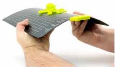
Remove the flex bed from the magnetic base. Gently twist the flex plate until the print "pops" off the print surface. Place the flex bed back on the printer for the next print.
natural_image
Hands holding a gray cutting board with yellow plastic components (no text or symbols visible)10-1.09 Congratulations! Your first 3D print is complete, your TAZ SideKick is ready to go to work!

natural_image
Yellow octopus-shaped object with six legs, enclosed in a yellow hexagon on a grid background (no text or symbols)
Your print bed is now cooling. Do not attempt to remove your 3D printed object before the print bed moves forward. Attempting to do so could either burn your skin on the hot end or print bed, damage your printer or print bed surface, or damage your 3D printed object.

When the print is finished, the X-Axis gantry will travel to the top of the printer and hold itself in place using magnets in the frame.

If using a sharp object on the Glass/PEI bed, exercise caution when using it. The blade can cut, gouge, or cause other damage to the print surface. Caution should also be exercised to avoid causing personal injury during the print removal process. Avoid prying prints up and away from the bed.

Congratulations! You have completed your first print on your TAZ SideKick!
For more projects, ideas, and ready-to-print models visit download.lulzbot.com/3D_Models/.

natural_image
Abstract gray swirl design with no text or symbols11
Tool Heads & Accessories
11-1 Tool Head Information
Why a variety of Tool Heads?
At LulzBot we produce a collection of Tool Heads for a variety of operations. Selecting the right Tool Head for the job is the first step to 3D printing perfect parts!
The Tool Head on a LulzBot 3D printer is the part that extrudes the plastic filament in a molten form and deposits it on a printing platform by adding successive layers on top of each other. The Tool Head is made of many distinct parts including a motor to drive the plastic filament (the cold end) and a nozzle to extrude the plastic (the hot end).
The cold end is the upper portion of the Tool Head. No heat is ever applied to this part of the Tool Head. The cold end consists of the motor and hob gear, pushing the solid strand of 3D printer filament into the hot end.
The hot end is where filament transitions from a solid to molten and then is extruded onto the print bed. The heat break, in combination with the heat sink and fan, prevents the filament from melting too soon by maintaining a thermal boundary where filament first begins to encounter elevated temperatures. Below that, an electric heater cartridge heats up a metal heater block which transfers heat to the nozzle. Nozzles come in different diameters that effect the resolution of the 3D print. Small nozzle diameters of 0.25mm to 0.5mm provide complex detail, but are limited on the volume of filament they can extrude quickly. Larger nozzle diameters of 0.8mm all the way up to 1.20mm and even 2.00mm lose some detail in exchange for speed.
The material the nozzles are made from are directly related to the material you are printing. Brass and coated copper nozzles are perfect for soft, everyday printing of non-abrasive filaments. PLA, ABS, TPU, HIPS, Nylon, etc. Hardened Steel nozzles come into play when you need additional wear resistance from filled or abrasive materials like glow-in-the-dark, bio, glass, metal, or carbon fiber filled filament.
Along with these nozzle diameter and material variations, each Tool Head is fine tuned to the specific purpose of the unit. Large heater blocks and bigger diameter nozzles require longer melt zones and hotter heater cartridges to properly maintain optimal temperature. Motors and gearing ratios can be different for the force and speed at which material can be fed through the extruder. It's not just a simple nozzle diameter difference from Tool Head to Tool Head.
The LulzBot Universal Mounting System allows users to change to the SK175, SK285, SL, SE, HE, HS, HS+, M175, and H175 Tool Heads based on application. Tool heads with the Universal Mounting System can be used interchangeably between the Mini 2, TAZ Workhorse, TAZ Pro line, and SideKick 3D printers. The older LulzBot Mini 1 and TAZ 5/6 generation of printers can be upgraded to the Universal Mounting System with the use of a LulzBot Universal Mounting System Adapter giving added longevity to those trusted printing platforms.
The real advantage to buying Tool Heads from a reputable source, like LulzBot, is we can provide you with some expertise and insight. Our support team is comprised of users who 3D print almost every day. They can give you some recommendations on which Tool Head will be the best fit for your application and help solve challenges, should they arise.
That means you can get the quality Tool Head you need, get some insight from other users, and know it's coming from a company that stands behind its products.
Tool Head Information 11-1
LulzBot Universal Mounting System Tool Head Line
The ability to change Tool Heads based on your printing needs gives you the ability to rapidly change the print speed and quality from your TAZ SideKick. Below you will find a description of each of the Tool Heads currently in the LulzBot product line. Visit shop.lulzbot.com/tool-heads for updates and additions to our ever expanding line of Tool Heads.
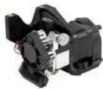
SK175 Tool Head | 1.75 mm | Single Extruder | 0.5 mm
The SK175 (SideKick 1.75mm filament) is an excellent budget-friendly option for beginners to 3D printing. The brass nozzle works well with materials like PLA or PETg and has excellent heat transfer. Designed specifically for the TAZ SideKick, the SK175 features an open fan shroud for easy viewing of your first layer and can be easily swapped out later for a higher end Tool Head thanks to LulzBot's Universal Tool Head Mounting system. (Only compatible with TAZ SideKick)

SK285 Tool Head | 2.85 mm | Single Extruder | 0.5 mm
The SK285 (SideKick 2.85mm filament) is an excellent budget-friendly option for beginners to 3D printing. The brass nozzle works well with materials like PLA or PETg and has excellent heat transfer. Designed specifically for the TAZ SideKick, the SK285 features an open fan shroud for easy viewing of your first layer and can be easily swapped out later for a higher end Tool Head thanks to LulzBot's Universal Tool Head Mounting system. (Only compatible with TAZ SideKick)

SL Tool Head | 2.85 mm | Single Extruder | 0.25 mm
The SL (Small Layer) is our highest detail Tool Head. Capable of producing layers down to 50 microns, or 1/30th the thickness of a penny, the SL is excellent for producing incredibly detailed prints. Perfect for making jewelry, dental models, tabletop figurines, or applications where layer resolution is paramount. Note: The SL Tool Head is intended for advanced users. The micro nozzle size requires some practice in order to be successful. Not recommended for Wood or Metal filled filaments.
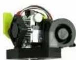
SE Tool Head | 2.85 mm | Single Extruder | 0.5 mm
The SE (Single Extruder) Tool Head is our most versatile and reliable model. Its tried and true design and construction have been standard on the Mini 2 and TAZ Workhorse for years. This Tool Head allows you to print in a wide variety of materials and temperatures from flexible TPU filaments to ABS and PLA. With its 0.5mm nozzle, you are able to complete your prints faster than other 3D printer brands making it an excellent solution in the industrial production setting.

HE Tool Head | 2.85 mm | Single Extruder | 0.5 mm
The HE (Hardened Edition) Tool Head is optimized for use with industrial grade materials and filaments with high abrasive properties or carbon fiber reinforcement. With its hardened steel drive gear and nozzle, this Tool Head is made to run tough materials over and over without wearing out. The 0.5mm nozzle affords a high degree of precision for printing. Hardened Steel nozzles generally require higher temperature when printing than traditional nozzles.
11-1 Tool Head Information

HS Tool Head | 2.85 mm | Single Extruder | 0.8 mm
The HS (Hardened Steel) Tool Head is optimized for use with industrial grade materials and filaments with high abrasive properties or carbon fiber reinforcement. With its hardened steel drive gear and nozzle, this Tool Head is made to run tough materials over and over without wearing out. The 0.8mm nozzle makes the creation of high strength jigs and fixtures fast and cost effective. Hardened Steel nozzles generally require higher temperature when printing than traditional nozzles.

HS+ Tool Head | 2.85 mm | Single Extruder | 1.20 mm
The HS+ (Hardened Steel +) is our largest layer Tool Head optimized for speed and use with industrial grade materials and filaments with high abrasive properties or carbon fiber reinforcement. The 1.2mm nozzle makes the fabrication of high strength, high speed parts obtainable with an extrusion rate of up to 205 grams per hour. Hardened Steel nozzles generally require higher temperature when printing than traditional nozzles.

H175 Tool Head | 1.75 mm | Single Extruder | 0.5 mm
The H175 (Hemera 1.75mm) features state-of-the-art components and design for an amazing hassle-free 3D printing experience. Designed for use with 1.75mm filaments and utilizing genuine E3D components, this Tool Head has been shown to reduce jams, produce accurate prints, and have the smallest Tool Head footprint in our lineup. The true Dual Drive allows for excellent control when printing with flexible materials.

M175 Tool Head | 1.75 mm | Single Extruder | 0.5 mm
The M175 (Mosquito 1.75mm) features state-of-the-art components and design for an amazing hassle-free 3D printing experience. Designed for use with 1.75mm filaments and utilizing American made components from Slice Engineering, this Tool Head has been shown to reduce jams, produce accurate prints, and utilize the highest wattage heater cartridge in our lineup for fast heat up times. The true Dual Drive allows for excellent control when printing with flexible materials.

natural_image
Collection of eight black industrial motors with visible internal components and mounting brackets (no text or symbols)Tool Head Removal 11-2
11-2.01 From the Main menu, select Motion, Park Nozzle. Turn the printer power switch to the OFF position, Locate the Tool Head on the X-axis. Slip the black flexible loop off the post of the thumbscrew. Unplug the Tool Head wiring harness from the Tool Head mount connector.

natural_image
Close-up of a black mechanical device mounted on a metal frame, labeled 'LULZBOT' (no other text or symbols visible)
natural_image
Close-up of a green and black robotic device with a red arrow indicating a joint or adjustment (no visible text or symbols)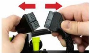
natural_image
Close-up of hands connecting black and green connectors with red directional arrows indicating movement (no text or symbols)11-2.02 Next, remove the thumbscrew on the rear of the Tool Head Mount by turning counterclockwise.

natural_image
Close-up of a hand inserting a yellow ball into a black mechanical component with a red arrow indicating direction (no text or symbols visible)11-2.03 Supporting the Tool Head, turn the two top thumbscrews counterclockwise to remove. Set the Tool Head aside in a safe location for later use.
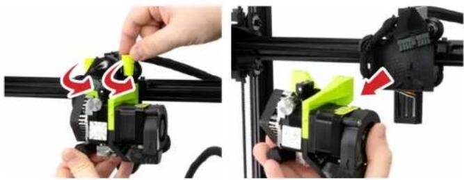
natural_image
Two-step industrial assembly process showing hand tool application on a black rail bar, with green and red arrows indicating motion direction (no text or symbols)
HOT SURFACE BURN HAZARD. CONTACT MAY CAUSE BURNS. DO NOT TOUCH THE HOT END.
Allow the Tool Head to cool to room temperature before removing. The hot end on the extruder can heat up beyond 180°C (356°F) and can burn your skin if you touch it.

NOTE: The Tool Head pictured may vary depending on the configuration of your SideKick.
Because of the unique LulzBot Universal Mounting System, these instructions will be the same for any of the Tool Heads selected with the SideKick.

Do not let the Tool Head fall during this process. Damage to the Tool Head and/or Print Bed can occur.
11-3 Tool Head Installation

NOTE: The Tool Head pictured may vary depending on the configuration of your SideKick.
Because of the unique LulzBot Universal Mounting System, these instructions will be the same for any of the Tool Heads selected with the SideKick.
11-3.01
Locate the Tool Head mount on the X-Axis at the top right of the 3D printer. Slide the Tool Head mount to the center of the X-Axis gantry. Line up the Tool Head on the mount. Supporting the Tool Head, insert and turn the two top thumbscrews clockwise to tighten.
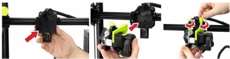
natural_image
Three-panel image showing a hand operating a 3D printer with green and red adjustment arrows (no text or symbols visible)11-3.02
Next, there is a small hole in the back of the Tool Head Mount above the BLTouch. Insert the thumbscrew into the hole and turn clockwise until finger tight.

natural_image
Close-up of a hand inserting a small electronic component into a device, showing wiring and color change (no text or symbols visible)11-3.03
With the printer power switch in the OFF position. At the top of the Tool Head locate the Tool Head wiring harness and Tool Head mount connector. Plug the Tool Head wiring harness into the Tool Head mount connector. Slip the black flexible loop over the post of the nearest thumbscrew.

natural_image
Three-panel image showing a hand holding a black cable connector, a green 3D-printed device with red arrows indicating assembly, and a LULZBOT-branded mechanical assembly (no readable text or symbols)Tool Head Installation 11-3
11-3.04 Once the new Tool Head is mounted on the printer, flip the red power switch to the ON position to turn on the TAZ SideKick. (Switch will illuminate red when powered on.)

natural_image
Close-up of a red toggle switch with 'O' and 'I' symbols, mounted on a vehicle (no readable text or labels)11-3.05 Your TAZ SideKick will now power on. Printers equipped with the gLCD screen will start up with the LulzBot and Marlin splash screens before the Home Screen as the printer prepares itself to operate.
11-3.06 From the Home Screen, scroll to select Tool Heads, then scroll to [select Tool Head installed].

N-307 Your TAZ SideKick now has the correct firmware installed to print with your selected Tool Head and is ready to print!

natural_image
Close-up of a black LULZBOT mechanical assembly mounted on a metal frame (no visible text or symbols)
Changing the Tool Head WITHOUT the gLCD Controller:
To change the Tool Head you will need to access the printer using Cura LE on your computer.
Connect your SideKick 3D printer to your computer using the USB cable.
Open Cura LulzBot Edition.
Cura LulzBot Edition is available from LulzBot.com/Cura.
In the top right-hand menu, Select the Settings drop-down arrow > Printer > Add Printer
Select LulzBot SideKick, [tool head being installed], and click Add Printer.
Select Finish.
Select Manage Printers
Confirm that the LulzBot SideKick [tool head installed] is selected, and click Upgrade Firmware.
Select Automatically Update Firmware.
The Update EEPROM checkbox should be checked by default.
Close any dialog windows after the firmware has been updated.
11-4 Filament Information
Filament Quality
LulzBot is happy to offer users an open filament model. This means that you have access to the most extensive selection of 3D printing materials. Regardless of what type of filament you print with, using high-quality material is important to your final print results.
Taking all the factors of 3D printing into consideration is important when looking at the cost of a project. A higher overall cost results from the combination of wasted filament and lost time when a print fails.
Selecting filament produced by good manufacturers is critical to obtaining high-quality prints with efficient use of time on your LulzBot 3D printer. LulzBot takes the guesswork out of the equation for you. We evaluate every material we carry, so you get the highest quality material every time you buy filament from us. Shop our full range of materials at https://shop.lulzbot.com/filament
Filament Selection
Your LulzBot TAZ SideKick Desktop 3D Printer is capable of printing advanced and expert level filament materials including: PLA, ABS, ASA, PETg, Nylon, TPU, PC-ABS, Polycarbonate, and more. LulzBot offers users the option to print with both filament diameter standards, 1.75mm or 2.85mm depending on the Tool Head selected. In addition, new materials are frequently being added to our catalog, each thoroughly tested to develop the profiles included in Cura LulzBot Edition.
Filament Temperature Guide
| Filament | Purging Temperature (°C) | Part Removal Temperature (°C) | Print Bed Preparation (See maintenance section for more information) |
| ABS, ASA, HIPS 220 50 Isopropyl alcohol wipe | |||
| PLA 180 45 Isopropyl alcohol wipe | |||
| PETg 220 50 Bed adhesive | |||
| Bridge, PCTPE, Nylon 910 220 50 Bed adhesive | |||
| Ninjaflex, PolyFlex, TPU 200 Fully Cooled Plain Glass or Bed adhesive | |||
| PA-CF 220 50 Isopropyl alcohol wipe | |||
| PolyCast 180 45 Isopropyl alcohol wipe |
Contact the filament manufacturer for more details on materials without profiles included in Cura LE.
Graphical LCD Controller 11-5
Graphical LCD Controller (gLCD)
More than just a "screen", the Graphical LCD Controller, or gLCD, allows you to print with the LulzBot TAZ SideKick printer without needing to have a computer connected or using host software such as Cura LulzBot Edition. This will allow for more efficient space in the workspace and free up a computer for other tasks.
The gLCD Controller features a fully functional printer interface equipped with a rotary encoder and an SD card slot for tether-less, mobile printing.
The gLCD Controller is perfect for normal day to day printing and will be used in the majority of your print jobs. However, in some instances, you will want to use Cura instead of the gLCD. A few examples of when you would want to plug the USB cable back in and use Cura:
- A number of manual movements are required to perform calibration checks. Because of this it is easier and faster to make the required manual movements within Cura. Calibration checks can be done with the gLCD, but require a number of repetitive menu selections.
- Cura is the preferred printer host software, as the inclusion of quick print profiles, the combination of slicing engine, and printer host communications allows for easy all-in-one use.


NOTE: LulzBot recommends only using SD cards 32GB or smaller with the TAZ SideKick gLCD Controller.

Because the LulzBot TAZ SideKick can be controlled by the gLCD and by host software, caution is advised when connecting to the printer through USB as the print can be interrupted when connecting or disconnecting the USB cable.
A general rule is: once you have started a print with either the gLCD, Cura, or another printer host, for the rest of the print use only that controller.
When printing with the gLCD, never try to connect through USB in the Cura host software; wait until the print is complete, and then connect in Cura.
Tool Heads & Accessories
11-6 Print Bed/Adjustable Feet

Glass/PEI Print Bed
The Glass/PEI print bed surface comes standard on the TAZ SideKick. It features a PEI (Polyetherimide) sheet laminated to a borosilicate glass plate and PCB bed heater in a modular system that provides improved ease-of-maintenance, increased versatility, and better heat uniformity across the bed surface.
The Glass/PEI print bed is effectively two surfaces in one. Depending on the filament in use, print on PEI or flip the surface over to print directly on plain glass or experiment with other print substrates. Keep a spare Glass/PEI Print bed on hand to increase up time when your PEI surface needs maintenance or replacement. This system ensures your LulzBot SideKick is going strong for years to come.

natural_image
Close-up of a LULZ BOT solar panel with grid pattern and mechanical components (no readable text or symbols)Octograb™ Magnetic Bed Option
The OctoGrab™ Magnetic Bed system surface configuration is an optional print surface for the TAZ SideKick. Enjoy the convenience of removing prints easily from our OctoGrab™ Magnetic Bed system! High temperature neodymium magnets pressed into a 6061 aluminum plate, spring steel top sheet, and laminate sheets of PEI and Polycarbonate come together to make the LulzBot OctoGrab Magnetic Bed!
These rare earth neodymium magnets do not lose magnetism, even after long or high temperature print jobs. Instead of struggling to remove parts directly from your 3D printer, you can now quickly remove the entire OctoGrab™ spring steel PEI sheet from the print bed along with your finished 3D printed part. Take your magnetic OctoGrab™ spring steel print surface and the finished part to a comfortable work area, bend the flexible OctoGrab™ spring steel bed in any direction, and your 3D print should release from the smooth PEI surface with ease.
The replaceable spring steel sheet has a layer of polycarbonate film on the back and a smooth sheet of PEI on the top printing surface. The PEI sheets are comparable to LulzBot's original glass/PEI printing surface but offer a stronger grip of 3D prints to the 3D printing bed during printing and even easier release of finished 3D prints.

natural_image
Close-up of a black mechanical component with a red circular button labeled 'O' (no text or symbols beyond the label)Adjustable Leveling Feet
The TAZ SideKick is equipped with two threaded leveling feet for easy adjustments.
The front feet of the printer frame can be adjusted by turning clockwise or counterclockwise to assist in leveling the printer. When raising or lowering the adjustable foot, you're not leveling the printer. You are adjusting the printer to a surface that's not level. The desired outcome when raising or lowering an adjustable foot is to stop the printer from rocking.
Filament Runout Sensor 11-7
Filament Runout Sensor Option
Your TAZ SideKick 3D Printer is capable of utilizing a Filament Runout Sensor. This sensor can be installed from the factory using the online configurator, or it can be purchased as an additional part later.
When installed, the Filament Runout Sensor will automatically detect when your printer is running out of filament. The sensor will send the printer a signal to pause the print until the filament can be changed manually. This can prevent failures on prints when you aren't certain if you have enough filament to complete the job.
If the Filament Runout Sensor option was not selected when the Taz SideKick was originally configured, you can order one by contacting LulzBot. Installation is simple using the instructions provided at https://ohai.lulzbot.com.
Filament Runout Sensor Option Installation
11-7.01 Locate the built in guide tube holder on the left side of the printer frame (above the Spool Mount). Loosen the thumbscrew by turning it counterclockwise - DO NOT remove it. Rotate the guide tube holder down 90°. Retighten the thumbscrew by turning clockwise. Snap the Filament Runout Sensor on to the guide tube holder.

natural_image
Close-up of a hand holding a black cable with a red arrow pointing to a green and yellow mechanical component (no text or symbols visible)11-7.02 Remove the Filament Guide Tube from the stock bracket. Next, insert the Filament Guide Tube into the exit end of the Filament Runout Sensor. Return to step 7-5.03 to finish set up and installation.

natural_image
Close-up of a hand holding a small object with a red arrow pointing to a black mechanical component (no visible text or symbols)
natural_image
Close-up of a black plastic electrical connector with a cable (no visible text or symbols)Your TAZ SideKick will print without the optional Filament Runout Sensor, however you will need to make sure that there is enough filament to finish the print or manually pause the printer and do a filament change mid print.
The filament guide tube is a critical part of the Tool Head assembly. Failure to install the filament guide tube can have a detrimental effect on print quality.
With the Filament Runout Sensor installed, only feed filament into the sensor in the direction shown. Failure to do so may damage the sensor.
Tool Heads & Accessories

natural_image
Abstract gray swirl design with no text or symbols12
Technical Specifications
What is Open Source Hardware?
All LulzBot 3D hardware designs and software packages are published under the GNU General Public License (GPLv3) and/or the Creative Commons (CC BY-SA 4.0). That means our products are completely open source, empowering users to modify them independently and even adapt them to their own particular needs. Users can then share those modifications with the entire LulzBot community to improve everyones experience. Open source hardware provides people the freedom to manage their technology while sharing knowledge and encouraging commerce through the direct exchange of designs. The software is also open source and it continues to keep growing through the contributions of users worldwide.
Open source hardware is all about allowing others to build on and improve existing hardware. A worldwide community of makers including students, hobbyists, artists, programmers, and professionals, has gathered around the LulzBot 3D printing platform. Their contributions have added up to an incredible amount of accessible knowledge that can be of enormous help to novices and experts alike. By directly communicating with customers, communities, and developers, LulzBot can access innovative input from outside the company to improve our products to better fit your needs.
Opens source is a participative development practice. Designers get inspired by each other and build on top of each other's work in an evolutionary process. Ideally, the collaborative nature of the open source environment is not a one way street, but rather an exchange in both directions. The license allows modifications and derivatives to be created by anyone. These altruistic improvements on the original design are shared with the original licensee and eventually implemented back into the final product. Much of the innovation throughout history has been due to individuals building on preexisting ideas and sharing the results. Therefore, in open source, the end customer has the potential to improve the product not just for themselves, but for everyone.
Openness of resources is a must to allow the community to reuse, develop, and improve open-source designs. We maintain all of our resources on a publicly available source code repository called Gitlab. This makes it easier to track changes to the files. It also makes it easier for people like you to send improvements back to LulzBot. If you have design modifications that you think will improve the product for yourself or others, submit them to the LulzBot GitLab at https://gitlab.com/lulzbot3d.
Open source works best when information about modifications and design improvements are shared in both directions, from manufacturer to customer and customer back to manufacturer. Please consider sharing your ideas with us on our GitLab.
FEATURES
Build Volume
Available in two build volume sizes to meet your printing needs. The 289 and larger 747 give you the space you need to be productive.
Tool Head

Choose from any of the Universal Mount Tool Heads from LulzBot. Tool Heads install easily by hand on the TAZ SideKick thanks to a unique design that uses large thumbscrews.
Build Platform

Choose from the PEI coated borosilicate glass print surface or the OctoGrab™ removable magnetic flex bed for frustration free print removal.
Automatic Bed Leveling
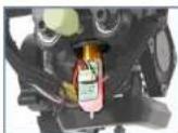
Every TAZ SideKick features a genuine ANTCLABS BLTouch* which provides state of the art automatic mesh bed leveling.
Belt Drive System

With its high precision belt drive in all axes, the TAZ SideKick is able to print freely at a variety of layer height resolutions. This eliminates the Z banding or Z wobble issues that can arise from lead screw machines.
Open Source Advantage
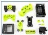
Over 50% of the parts on the TAZ SideKick are 3D printed and open source, allowing the user to replace or service their machine in the field with ease.
| 289 | 747 |
| Build Volume | |
| 6^3/_6 × 6^3/_6 × 7^1/_6 162 x 162 x 181 mm | 9" × 9" × 9^1/_4" 231 x 231 x 248 mm |
| Operating Footprint | |
| 22" × 25" × 24" × 28" | |
| Net Weight | |
| 18.92lb 20.35lb | |
| Bed Leveling | |
| Genuine ANTCLABS BLTouch® | |
| Filament Feed | |
| Direct Drive | |
| Print Head | |
| LulzBot Universal Mounting System(Compatible with all LulzBot Universal Mounting System Single Extruder Tool Heads) | |
| Filament Diameter (configured option) | |
| 1.75mm or 2.85mm*Dependent on Tool Head selected.LulzBot Open Filament System:Compatible with most high-quality materials; ABS, PLA, ASA, PETg, TPU, PC, PP, Nylon, metal fill, bio fill, carbon fiber/glass composites and more. | |
| XYZ Motion & Resolution | |
| Motion: Belt Driven Resolution: 10, 10, <5μ | |
| Ambient Operating Temperature | |
| 5^ C to 32^ C (41°F to 113°F) | |
| Build Plate (configured option) | |
| Glass/PEI Bed - Heated borosilicate glass with PEI surfaceMaximum print surface temperature: Up to 110^ C (230°F) .OctoGrabTM Removable Magnetic Bed - Heated magnetic flexible spring steel with PEI surface, PC undersideMaximum print surface temperature: Up to 110^ C (230°F) | |
| Power | |
| Single Phase, 100VAC - 240VAC, 50/60Hz, Auto-switching MEAN WELL RSP-150-24, 24VDC, 150W, 21A | Single Phase, 100VAC - 240VAC, 50/60Hz, Auto-switching MEAN WELL LRS-350-24, 24VDC, 350W, 14.6A |
| Slicing Software | |
| Cura LulzBot Edition - Version 3.6.25 or newer | |
| Operating System | |
| Windows, GNU/Linux | |
| Firmware | |
| Marlin | |
| Supported File Types | |
| .stl, .obj, .x3d, .3mf, .png, .jpg | |
| Warranty | |
| Includes one-year factory warranty.Optional one, two, and, three-year extended warranties available. | |

natural_image
Abstract gray swirl design with no text or symbols13
Maintenance
13-1 Maintaining SideKick
Preventive Maintenance
Very little maintenance is required to keep your LulzBot TAZ SideKick 3D printer running. Depending on your rate of use, you will want to perform a quick check of your printer every 2 to 4 weeks. The following maintenance guidelines will keep your printer printing quality parts.
Your SideKick is built to last, however, should any of the common wear parts on your SideKick happen to fail, LulzBot provides a complete selection of replacement parts at https://shop.lulzbot.com.
Cleaning & Inspection
With regular use, dust and debris can collect underneath the printer and may cause interference with the Y-axis motion. Check for debris in the belt pulleys that may interfere with smooth movement. Clean and dust the area underneath and surrounding the printer daily to prevent this. Make sure that the hot end and print bed are at room temperature before beginning any cleaning or maintenance unless otherwise noted.
All electrical cables and connectors should be checked for damage and whether they're tightly connected. Pay special attention to the hot end and heated bed connectors, as these take up higher current, thus posing a potential fire hazard.
Look for signs of wear or physical damage. Check roller wheels, fans, belts, and all moving parts for wear. Ensure all bolts, screws, and belts are not loose.
Inspect the frame and look for play between components.
Print Bed Care
Your SideKick print bed does not require manual bed leveling. Prior to each print, the SideKick will automatically level the bed using the built in Bed Leveling Sensor. Inspect the Bed Leveling Sensor on a regular basis.
The following procedure applies to both the Glass/PEI and PEI coated OctoGrab™ print beds:
Between prints or when you notice prints not adhering to the print bed, wipe down the bed using a lint free cloth and a 50/50 mix of water and isopropyl alcohol to clean the surface of any dust or oils from touching the PEI. If you want to really help bed adhesion, you can take a green or red Scotch-Brite™ pad and add a little of the 50/50 mix of water and isopropyl alcohol to the PEI and lightly scuff the PEI surface. Then wipe the bed using a lint free cloth and a 50/50 mix of water and isopropyl alcohol to clean the surface of any dust or oils.
Maintaining SideKick 13-1
Tool Head Care
Make sure the Filament Guide Tube is attached and functioning properly. The Filament Guide Tube is a critical part of the Tool Head assembly. Maintain the Filament Guide Tube to maximize final print quality.
Every 2-4 weeks carefully clean your hot end cooling fans. Gently blow any dust away with short bursts from a can of compressed air.
Running a high quality cleaning filament through the printer every few prints, when changing materials, or when you start to notice issues in printing can help prevent clogs and jams.
Over time, you may also experience an accumulation of melted material on the nozzles and heater blocks. It can be cleaned by heating the hot end up to 205°C (401°F) and then carefully wiping the affected areas using a maroon 7447 Scotch-Brite™ 320 grit general purpose scrubbing pad. Use caution when cleaning the heater block while it is heated to melting temperature.
SK175, SK285, SE, HE, SL, HS, HS+ Tool Heads:
Using a dental pick or similar tool, clean the filament debris out of the extruder hob gear on the tool head. Dirty extruder gears can produce squeaking noises caused by filament dust or can cause inconsistent filament extrusion resulting in poor print quality. Use compressed air to clear any residual filament from the tool head. Reset the tool head tension as described in Chapter 9 (section 9-1.10 a) after reassembly.
M175 Tool Head:
While the dual drive gears of the M175 extruder usually remain clean, you should inspect the drive gears from time to time by turning the filament tension knob all the way out (counterclockwise) and removing it from the quick release lever. The quick release lever will open, exposing the dual drive hob gears. Use compressed air to clear any residual filament from the tool head and reassemble. Reset the tool head tension as described in Chapter 9 (section 9-1.10 b) after reassembly.
Axis & Guide Checks
The rollers of each axis should slide along the aluminum extrusion profile easily, friction-free, and without any play. All axes should move freely when the power to the machine is off.
The rollers may catch and accumulate some dust. For optimal print results, periodically clean the rollers by following these steps:
Take a lint free damp cloth and place it on the roller you're going to clean. Turn the roller to clean all dust from it. After cleaning all rollers. Also wipe down the aluminum extrusions they run on.
If you notice that rollers have signs of wear, dents, or other damage, replacements are available at https://shop.lulzbot.com.

HOT SURFACE BURN HAZARD. CONTACT MAY CAUSE BURN. DO NOT TOUCH THE HOT END.
The hot end on the extruder can quickly heat up beyond 180°C (356°F) and can burn your skin if you touch it.

The filament guide tube is a critical part of the Tool Head assembly. Failure to install the filament guide tube can have a detrimental effect on print quality.
13-1 Maintaining SideKick
Belt Tension Adjustment
Tensioning belts doesn't have to be done often, but over long periods of use or after moving of the printer repeatedly, you may need to re-tighten the belts on your 3D printer. Pluck the four belts to check their tension. They should resonate like a guitar string. The tension of the belts should be similar.
If belts are too loose, the belts can slack and will not respond well to sudden changes in speed and direction, with degrading print surface quality becoming noticeable. If belts are too tight, motors will be stressed and can overheat.
For the Z-axis, using the gear knobs on the top of the printer frame: To loosen the belt, turn the gear counterclockwise to loosen tension on the belt. To tighten the belt, turn the gear clockwise.
For the X-axis, using the gear knobs on the left and right side of the printer gantry: To loosen the belt, turn the gear counterclockwise to loosen tension on the belt. To tighten the belt, turn the gear clockwise.
The Y-axis belt can be tightened using the gear knob found on the front of the Y-axis plate.
Deep Clean
Two or three times a year, perform a deep clean and inspection of your SideKick.
Switch the printer OFF and unplug the power cord and before starting the following procedures:
Unscrew the screws holding the control box panel and swing the panel open to gain access to the control box. Using compressed air, carefully clear the fans and area around the control board of any dust or debris that may have collected inside.
Inspect all electrical connections on the control board to ensure they are seated securely. Make sure to turn the printer OFF and unplug it from the power source before touching any of the connectors!
Once the control box is clean, swing the panel closed and tighten the screws.
Locate the power supply on the bottom of the machine under the Y-Axis print bed. Using compressed air, also clear the power supply and power supply fan of any dust or debris.
Maintaining SideKick 13-1
Firmware Updates
The latest version of Cura LulzBot Edition (LE) contains the latest stable version of firmware for each included LulzBot 3D Printer and tool head combination.
Follow the instructions available at www.LulzBot.com/Cura to download and install the latest version of Cura LE.
- Open Cura LE.
- Power on your LulzBot 3D Printer and connect it to your computer using the supplied USB cable.
- Record or verify possession of the Extruder steps per unit.
- Select your LulzBot 3D Printer from the Settings menu.
- Select the Settings menu > Printer > Manage Printer(s) > Upgrade Firmware > Automatically Upgrade Firmware to start the firmware update process.
- Update your Extruder steps per unit and perform a test print.
Need Help?
Visit our web site, www.LulzBot.com for replacement parts, product support, a list of authorized service centers in the US and customer service contact information. Please have the printer serial number (located on the white label of your product) available for better assistance.

WARNING - Electric shock can kill.
ALWAYS disconnect the printer by unplugging the power cord before attempting to enter the electronics box enclosure.
Failure to follow warnings could result in personal injury, death, or property damage.

If you have an issue with your printer or are dissatisfied with the performance of this product please contact LulzBot at:
Web: www.LulzBot.com/Support
Email: Support@LulzBot.com
Phone: +1-701-809-0800

natural_image
Abstract gray swirl design with no text or symbols14
Troubleshooting
14-1 Troubleshooting
Issue Possible Solution
| Poor Bed Adhesion Poor bed adhesion could be caused by a few different issues. The most common being an uncalibrated z-offset. | Your printers Z-offset can be adjusted through the gLCD menu on your printer by clicking the gLCD knob in once to bring up the main menu then navigating to:Configuration > Probe Z-Offset. |
| Z-offset is the distance between the nozzle of your tool head and the build surface of your printer. | Then, you can make your offset closer to the bed by turning the gLCD control knob counter-clockwise. You can make your nozzle further away from the bed by turning the knob clockwise.Once you have found a suitable setting for the z-offset, be sure to go back to the configuration screen and click Store Settings. |
| The further away the nozzle is from the bed, the less like your print is the stick to the surface. If this distance is too close to the build surface, you may get clogging due to the drive gear of the tool head grinding through the filament. | An example of modifying your z-offset is as follows. Note, these numbers may not match your printers settings and are purely for demonstration purposes.If you change the z-offset from -1.2 mm to -1.25mm, this will make your first layer more squished by bringing the nozzle closer to the bed. If you change the z-offset from -1.2 to -1.15, this will make your first layer less squished by moving the nozzle away from the bed.You can also adjust this setting in real time while your printer is laying down its first layer.To perform this during your printer's first layer, navigate to the tune menu on your gLCD and scroll down to z-offset. From here, you can tune the offset up and down, and the printer will adjust the first layer height as you adjust the settings.Remember to go back to configuration and store the settings once your printer is done as you are unable to access the configuration menu while the printer is printing. |
| If you are unable to get parts to print and you have already dialed in your z-offset, we can look into cleaning the build plate.1 Using a 50/50 mix of water and isopropyl alcohol, wipe down the bed to clean the surface of any dust or oils from touching the PEI.If you want to really help bed adhesion, you can take a green or red scotch brite pad and add a little of the water/ iso mix to the PEI and lightly scuff the PEI surface.2 Wipe down with the 50/50 mix again and add glue stick to your print surface.3 Doing this opens up the print surface to allow greater bed adhesion. | |
| If that still does not work for you, you may need to replace the PEI surface on the build plate if your printer has a Glass/PEI bed. The PEI is considered a consumable and can be user serviced using the guide below.www.lulzbot.com/learn/tutorials/pei-print-surface-maintenance |
Troubleshooting 14-1
Issue Code Explanation Possible Solution
Error Codes
| Mintemp | Temperature dropping below 0°C. Usually due to the printer not sensing a thermistor. | Check thermistor connection and if possible, test with a multimeter. Replace thermistor if necessary |
| Maxtemp | Printer sensing a hotend temperature above 305°C. If error appears when the printer is first turned on this can be caused by shorting thermistor wires. | Check that the thermistor wires are not touching each other. If the tool head is getting too hot, possibly a bad mosfet on the control board |
| Thermal Runaway | Temperature on the bed/tool head has swayed too far from the set temperature and caused the printer to stop heating. | Check to make sure that nothing is causing the tool head or the bed to cool down such as a room fan. |
| Homing Failed | The printer is not able to home itself in the x/y/z axis. | Check for any obstructions in the tool head or bed path. Homing sensitivity may not be sensitive enough. |
| Probing Failed | The printer's automatic bed leveling was unable to complete. | Check for any obstructions in the tool head or bed path. Check that the BLTouch is probing correctly and that the nozzle of the tool head is not contacting the bed before the probe. |
| Heating Failed | Printer was unable to heat the bed/tool head quickly enough causing the printer to shut off due to thermal protection. | Check to make sure that nothing is causing the tool head or the bed to cool down such as a fan. If possible, test the heater cartridge for a high resistance value. |
| Please Reset | Printer needs to be reset. | Power the machine off, then back on. |
14-1 Troubleshooting
Issue Possible Solution
| Jams/Clogs Partial or complete clogs canprevent filament from exiting the nozzle and will inevitably cause the extruder gear to bite into and chew through the filament.If you are experiencing a clog or a filament jam, we recommend performing a few cold pulls to try and remove any contaminants that may be in the nozzle. | When it comes to performingcold pulls(sometimes referred to as atomic pulls), set your tool head to the extrusion temperature of the filament you will be using to perform the cold pull.1 Push that filament into the tool head while the tool head is hot, then turn the temperatures of the hot end back down to around 100°.2 Keep pushing until you no longer see filament coming out and can no longer feel the filament going into the hotend and keep letting it cool off.3 Once it gets to 100° apply a little upward pressure on the filament like you are trying to pull it out. Not a lot of force though.4 Start heating the tool head back up to around 200°C again while pulling up a little.5 As the plastic softens, you will start to feel the filament elongating and once soft enough, the filament shouldpull right out leaving a nice plug at the end.You may need to perform this multiple times in an effort to remove anything that may be clogging your nozzle.If you are not able to clear a clog or jam using the above instructions, please reach out to our support team for further assistance. Contact information can be found near the end of this guide. |
| Filament Grinding Filament grinding is normallythe result of too much pressure in the hotend which prevents filament from exiting the nozzle.If anything is blocking the transport of the filament out of the nozzle of the printer the teeth of the gear will crew through the filament. | Check that your nozzle is not too close to the printer's bed.If it is too close to the bed, you will need to adjust your z-offset to bring the nozzle higher up. See theTroubleshootingsection onbed adhesionfor instructions on this process.Also, check your printing temperature as well as the tension on your filament idler.If printing too cold or if you have too much tension on the filament at the idler this will prevent the movement of filament and ultimately grind away at it. Try increasing your print temperature and loosening the tension on the filament idler a little bit.Clogs/filament jams can also cause the gears on the extruder to grind through filament. Please refer to theJams/Clogssection for more information. |
Troubleshooting 14-1
Issue Possible Solution
| Over Extrusion Over extrusion can be fairlyeasy to spot as the prints you are getting will either be slightly too large or appear to be pretty blobby.This is caused when too much filament is being extruded from the nozzle and can be caused by a number of issues. | 1 Be sure that the filament diameter is set correctly within your slicer.The most common filament diameters are 1.75mm filament and 2.85mm filament. Some manufacturers create 3.00mm filament and it is actually 3.00mm, while others state their filament is 3.00mm when it is actually 2.85mm filament.If you have access to calipers, check to ensure that you have the correct filament diameter set that corresponds with your installed tool head.2 Check for a worn nozzle.Even non abrasive filaments can wear the nozzle on your printer over time and will widen the opening where the filament comes out.This means that even though your nozzle started off as a 0.5mm diameter nozzle, due to wearing, it may be 0.6mm or even wider.This will cause more filament to be extruded than the printer thinks. Highly abrasive filaments such as glass/carbon fiber filed materials will wear through your nozzle faster than others. |
| Under Extrusion Under extrusion can be a little more difficult to diagnose.Your prints may appear like they are slightly hollow or maybe there are missing lines or extreme gaps on the print.Your top layers may have space between the lines of plastic.Like over extrusion, be sure that your filament diameter is set correctly in your slicer to ensure that the printer extrudes filament at the right speed. | 1 Check filament idler tension.If the tension on your filament idler is too loose, the gear that pushes filament into the hotend may not be fully engaging the side of the filament and can slip. This will prevent the filament from going into the hot end and cause a lack of plastic being extruded.2 A partial clog in the nozzle is another common cause of under extrusion.If there is debris preventing plastic from being extruded, it will cause under extrusion. If this is the case, you will usually see grinding through the filament and may need to perform a few cold pulls to try and remove any debris.Please refer to the Jams/Clogs section for more information regarding cold pulls |
14-1 Troubleshooting
Issue Possible Solution
| Layer Adhesion/Delamination Layer adhesion or delamination issues can stem from a few different places. | Depending on the filament used, you may need an enclosure.ABS tends to warp and shrink after it is printed and this can cause the layers to come apart. The use of an enclosure greatly reduces the speed at which the filament shrinks and helps minimize layer separation.Another reason for layer adhesion issues can be too thick of layers.Generally, the optimal printing layer height is going to be 25-75% of the nozzle diameter.For your SideKick, this equates to layer heights between 0.125 and 0.375mm. Smaller layer heights can be achieved through tuning, however larger layer heights will likely not be due to the physical limitations of the nozzle diameter. If you are printing too thick of layers, try reducing your layer height.When printing, temperature is a very important setting that may need to be adjusted for your printer.Not printing hot enough can cause layers to bond poorly to one another and increase the chance of layer delamination.If you are experiencing layer separation, try increasing the printing temperature by 5 - 10^ and try another test print. |
| Ghosting/Ringing Ringing or ghosting on a 3Dprint can usually be seen as a surface artifact on a print that appears next to a feature that has been printed.A lot of time this will appear almost like a rippling effect to the right or left of a surface feature such as text or a comer.This artifact is normally caused by something mechanical, such as a loose belt or a dirty bearing/extrusion/smooth rod. | Check for debris that may be causing the bearings/bushing to bind and ensure that the extrusion/rods are clean and free of debris as well. Inspect that the belts are tight. If they appear to be too loose, adjust their tension by turning the adjustment knobs on the axis which is loose.Another reason you may be experiencing ghosting/ringing could be that you might be printing too fast.Printing fast can create jerks on the printer when changing direction and this can introduce extra vibration on the printer and this vibration can show through on the print. Reduce the speed of your printing and try another test print. |
Troubleshooting 14-1
Issue Possible Solution
| Lines On Sides Of Print Lines on the side of your prints can be caused by a number of issues. | Usually this is a sign of belts that may be a bit loose. Tighten the belts using the belt tension adjustment knobs on your SideKick a little bit and try another test print. Horizontal lines that appear to be consistent may also be due to a bed that needs to be PID tuned.As the bed heats up and cools off, it will expand and contract by a small amount. This expansion and contraction can cause the bed to rise and lower by a very small amount and this will show as horizontal lines in the print.Performing a PID tune on your SideKick will help the printer calculate how much current to send to the bed and how quickly it will need to turn it on and off to more accurately regulate the bed temperature.Your printer is capable of performing an automatic PID tune.You can do this by navigating to the following menu and selecting thePID Autotune:Configuration>Advanced Settings>TemperatureFor more details on the PID Autotune process, contact customer support. |
| Support Information If you are experiencing other issues or need further assistance, reach out to our LulzBot Customer Support team. | Web: www.LulzBot.com/SupportEmail: Support@LulzBot.comPhone: +1-701-809-0800 ext 2Monday - Friday, 8:00 AM to 5:00PM Central Time |

natural_image
Abstract gray swirl design with no text or symbols15
Warranty & Support
15-1 Warranty & Support

IF YOUR SIDEKICK IS DAMAGED OR IS NOT WORKING PROPERLY, DO NOT RETURN TO THE STORE OR RETAILER.
If you have an issue with your printer or with the performance of this product please contact LulzBot at:
Web: www.LulzBot.com/Support Email: Support@LulzBot.com Phone: +1-701-809-0800
CUSTOMER FEEDBACK
Why keep a good thing secret? Share your LulzBot LOVE with the world! Tell coworkers, peers, friends, and family. Share your experience by writing a review or sharing your LulzBot TAZ SideKick projects on social media. Tag your projects with LulzBot on Instagram, Facebook, Twitter, and LinkedIn.
Not happy? We're here to help. Contact our friendly customer support team. We'd love to solve your problem and get you printing again!
WARRANTY AND SUPPORT
Your machine comes with a limited one-year warranty and customer support period including USA-based customer support available via email at Support@LulzBot.com or by phone at +1-701-809-0800 ext 2. For more information, please visit LulzBot.com/Support.
Extended warranties of one, two, and three years may be purchased to further protect your investment. Email Sales@LulzBot.com or call +1-701-809-0800 ext 1 for more information.
Warranty and customer support cover electrical, mechanical, and motion systems on the printer. Material issues are not covered by LulzBot customer support. Material questions and concerns should be directed to the material manufacturer. For more information about the warranty on your LulzBot 3D Printer visit:
www.LulzBot.com/content/shipping-standard-warranty-and-return-policies
SERIAL NUMBER LOCATION
Your 3D printer has a unique serial number for identification. The serial number is located on a sticker on the side of the electronics case on your printer. Please record your serial number for reference. In the rare event that you should need service or support, your customer support representative will need your serial number to assist you.
HOW TO OBTAIN WARRANTY SERVICE?
Please access and review the online help resources described below before seeking warranty service.
• LulzBot User Forum: forum.lulzbot.com/
Search the LulzBot User Forum for a solution. You may find an answer to your question there.
• OHAI Assembly Instructions: https://ohai.lulzbot.com/
View the LulzBot Open Hardware Assembly Instructions (OHAI) installation and assembly guides for your printer.
- CURA Firmware Flashing Tutorial: www.lulzbot.com/learn/tutorials/firmware-flashing-through-cura Flash the firmware on your printer using the Cura Firmware Flashing Tutorial
Warranty & Support 15-1
If the LulzBot Product is still not functioning properly after making use of these resources, please contact a LulzBot customer support representative
• LulzBot Customer Support: www.lulzbot.com/support
When contacting support, video or photos are extremely helpful to illustrate the issue(s) you have, if applicable.
A LulzBot representative will help determine whether your LulzBot product requires service and, if it does, will inform you how LulzBot will provide it.
When contacting LulzBot via telephone, other charges may apply depending on your location.
www.LulzBot.com/content/shipping-standard-warranty-and-return-policies
RMA REQUIRED FOR ANY RETURN
A Return Merchandise Authorization (RMA) number must be obtained from LulzBot before Customer can return any product for warranty service. A LulzBot representative will gather the appropriate account and product information and verify warranty status.
LulzBot must receive notification of the need for warranty service before the end of the applicable limited warranty period. LulzBot will supply instructions on how to properly pack, address, and indicate RMA number on your LulzBot product.
Any approved RMA should be considered provisional, based on verification of in-warranty status when the product is received by LulzBot. If LulzBot determines that the product is out-of-warranty, the customer will be notified. At the customer's discretion, LulzBot will either scrap the out-of-warranty product or return it to the customer for third party out-of-warranty repair.
THE WARRANTY MAY NOT AUTOMATICALLY INCLUDE COSTS INCURRED FOR SHIPPING DEFECTIVE PRODUCTS FOR INSPECTION AND/OR REPAIR, NOR FOR SHIPPING COSTS OF REPLACEMENT OR REPAIRED PRODUCT(S) BACK TO CLAIMANT. CUSTOMER IS RESPONSIBLE FOR ALL SHIPPING CHARGES FOR RMA PRODUCT REGARDLESS OF PRODUCT WARRANTY STATUS. IF LULZBOT PRODUCT IS WITHIN FIRST 30 DAYS OF PURCHASE, LULZBOT MAY CHOOSE TO COVER ALL SHIPPING EXPENSES INCURRED DURING BOTH INBOUND AND OUTBOUND SHIPMENTS FOR SERVICING.
The most current LulzBot Standard Warranty & Return Policies can be viewed at: www.lulzbot.com/content/shipping-standard-warranty-and-return-policies

A packaging material fee (\$75) may apply if you do not have your original product packaging for shipping and may delay the return process.

To obtain an RMA number, you must contact a LulzBot customer support team member by mail, email, or telephone as follows:
LulzBot
Customer Support Department 1001 25th Street North
Fargo, North Dakota 58102 USA
Email: Support@LulzBot.com
Telephone: +1-701-809-0800 ext 2
Phone support available 5 days a week, Monday through Friday: 8:00 a.m. to 5:00 p.m. Central Time.

natural_image
Abstract gray swirl design with no text or symbolswww.LulzBot.com/Support | Support@LulzBot.com | +1-701-809-0800 ext 2

www.LulzBot.com


- Cloning LulzBot Products
- CONTENT
- 01
- Introduction
- Congratulations!
- 02
- Meet Your SideKick
- 2-1 SideKick Key Components
- Printer Anatomy
- Tool Head Key Components 2-2
- Tool Head Anatomy
- 03
- Safety
- 3-1 Safety
- \*CA Prop 65
- INJURY HAZARD
- BURN HAZARD
- ELECTRIC SHOCK HAZARD
- Safety 3-1
- FIRE HAZARD
- AGE WARNING
- MODIFICATION NOTICE
- Cloning LulzBot Products:
- MAGNETIC HAZARD
- 3-2 Safety
- POWER SUPPLY
- OVERALL PROVISIONS
- DISCLAIMERS
- Safety 3-2
- INTENDED USE
- THIRD-PARTY MATERIALS
- SOURCE FILES
- 04
- Simple Set Up Guide
- 4-1 Simple Set Up Guide
- Simple Set Up Guide 4-1
- 05
- Unpacking
- 5-1 Unpacking
- RETAIN ALL PACKING MATERIALS.
- Unpacking 5-1
- 06
- 6-1 Printer & Y-Axis
- Standard & Optional Items 6-1
- Standard Items
- Optional Items
- 07
- Assembly
- 7-1 Electronics Enclosure Assembly
- Y-Axis Assembly 7-2
- 7-2 Y-Axis Assembly
- Tool Head Assembly 7-3
- 7-3 Tool Head Assembly
- 7-4 Spool Mount Assembly
- Guide Tube Assembly 7-5
- 08
- Slicer Installation & Set Up
- 8-1 Slicer Installation
- Slicer Installation 8-1
- 09
- Preparing SideKick to Print
- 9-1 Preparing to Print
- Preparing to Print 9-1
- 9-1.06a Changing Filament WITH the gLCD Controller:
- 9-1.06b Changing Filament WITHOUT the gLCD Controller:
- 9-1.07
- 9-1.08
- 9-1.09
- 9-1.10
- 9-1.11
- 9-1.12a Purge/Advance Filament WITH the gLCD Controller:
- 9-1/2b Purge/Advance Filament WITHOUT the gLCD Controller:
- Tool Head Tension 9-2
- 10
- Starting Your First Print
- 10-1 Starting Your First Print
- Starting Your First Print 10-1
- Glass/PEI Bed Option
- OctoGrab™ Flexible Bed Option
- 11
- Tool Heads & Accessories
- 11-1 Tool Head Information
- Why a variety of Tool Heads?
- Tool Head Information 11-1
- LulzBot Universal Mounting System Tool Head Line
- SK175 Tool Head | 1.75 mm | Single Extruder | 0.5 mm
- SK285 Tool Head | 2.85 mm | Single Extruder | 0.5 mm
- SL Tool Head | 2.85 mm | Single Extruder | 0.25 mm
- SE Tool Head | 2.85 mm | Single Extruder | 0.5 mm
- HE Tool Head | 2.85 mm | Single Extruder | 0.5 mm
- Tool Head Removal 11-2
- 11-3 Tool Head Installation
- 11-3.01
- 11-3.02
- 11-3.03
- Tool Head Installation 11-3
- 11-4 Filament Information
- Filament Quality
- Filament Selection
- Graphical LCD Controller 11-5
- Graphical LCD Controller (gLCD)
- 11-6 Print Bed/Adjustable Feet
- Glass/PEI Print Bed
- Octograb™ Magnetic Bed Option
- Adjustable Leveling Feet
- Filament Runout Sensor 11-7
- Filament Runout Sensor Option
- Filament Runout Sensor Option Installation
- 12
- Technical Specifications
- What is Open Source Hardware?
- FEATURES
- 13
- Maintenance
- 13-1 Maintaining SideKick
- Preventive Maintenance
- Cleaning & Inspection
- Print Bed Care
- Maintaining SideKick 13-1
- Tool Head Care
- SK175, SK285, SE, HE, SL, HS, HS+ Tool Heads:
- M175 Tool Head:
- Axis & Guide Checks
- Belt Tension Adjustment
- Deep Clean
- Switch the printer OFF and unplug the power cord and before starting the following procedures:
- Firmware Updates
- Need Help?
- WARNING - Electric shock can kill.
- 14
- Troubleshooting
- 14-1 Troubleshooting
- Troubleshooting 14-1
- 15
- Warranty & Support
- 15-1 Warranty & Support
- CUSTOMER FEEDBACK
- WARRANTY AND SUPPORT
- SERIAL NUMBER LOCATION
- HOW TO OBTAIN WARRANTY SERVICE?
- Warranty & Support 15-1
- www.LulzBot.com/content/shipping-standard-warranty-and-return-policies
- RMA REQUIRED FOR ANY RETURN
Brand : LulzBot
Model : TAZ SideKick 289
Category : 3D Printer