MSL10 - Uncategorized Megger - Free user manual and instructions
Find the device manual for free MSL10 Megger in PDF.

| Product Type | Loop/Line Impedance Tester |
| Brand | Megger |
| Model | MSL10 |
| Display | Backlit LCD, 3-line display |
| Measurement Functions | Loop impedance, Prospective Short Circuit Current (PSC), Voltage (AC) |
| Loop Impedance Range | 0.01 Ω – 2000 Ω |
| PSC Range | 0.1 A – 25 kA |
| Voltage Measurement | 0 V – 500 V AC, 45–65 Hz |
| Safety Rating | CAT III 300 V, CAT IV 150 V |
| Power Supply | 6 x AA alkaline batteries or rechargeable NiMH |
| Battery Life | Approximately 3000 tests |
| Dimensions (H x W x D) | 220 x 115 x 55 mm |
| Weight | 0.9 kg (including batteries) |
| Memory | 500 test results |
| Data Transfer | USB / Bluetooth (optional) |
| Protection Class | IP54 (dust and splash proof) |
| Standards | IEC 61557, IEC 61010 |
| Cleaning | Wipe with a damp cloth, mild detergent; do not immerse |
| Spare Parts / Repairability | Battery compartment, test leads, fuses (replaceable by user) |
Frequently Asked Questions - MSL10 Megger
User questions about MSL10 Megger
0 question about this device. Answer the ones you know or ask your own.
Ask a new question about this device
Download the instructions for your Uncategorized in PDF format for free! Find your manual MSL10 - Megger and take your electronic device back in hand. On this page are published all the documents necessary for the use of your device. MSL10 by Megger.
USER MANUAL MSL10 Megger
3 in 1 Stud/Metal/AC Voltage Finder
User Guide
This document is copyright of:
Megger Limited, Archcliffe Road, Dover, Kent CT17 9EN. ENGLAND T +44 (0)1304 502101 F +44 (0)1304 207342 www.megger.com
Megger Ltd reserves the right to alter the specification of its products from time to time without notice. Although every effort is made to ensure the accuracy of the information contained within this document it is not warranted or represented by Megger Ltd. to be a complete and up - to - date description.
For Patent information about this instrument refer to the following web site:
megger.com/patents
This manual supersedes all previous issues of this manual. Please ensure that you are using the most recent issue of this document. Destroy any copies that are of an older issue.
Declaration of Conformity
Hereby, Megger Instruments Limited declares that radio equipment manufactured by Megger Instruments Limited described in this user guide is in compliance with Directive 2014/53/EU. Other equipment manufactured by Megger Instruments Limited described in this user guide is in compliance with Directives 2014/30/EU and 2014/35/EU where they apply.
The full text of Megger Instruments EU declarations of conformity are available at the following internet address:
megger.com/eu-dofc
1. Introduction
The Stud Tester uses electronic signals to locate the edges of studs, joists or live AC 1-cables through plasterboard or other common building materials. Depth range can be selected between 1/2", 1" and 1.5" (12 mm, 25 mm and 36 mm). Once the edge of a metal or wooden stud or joist has been detected, the two detection LEDs of Stud locator illuminate and an audible tone is emitted.
1.1 Company web site
Occasionally an information bulletin may be issued via the Megger web site. This may concern new accessories, new usage instructions or a software update. Please occasionally check on the Megger web site for anything applicable to your Megger instruments.
www.megger.com
2. Safety Warnings and Standards
These safety warnings must be read and understood before the instrument is used. Retain for future reference.
2.1 Warnings, Cautions and Notes
This user guide follows internationally recognised definitions. These user instructions must be adhered to at all times.
Description
WARNING : Indicates a potentially dangerous situation which, if ignored, could lead to death, serious injury or health problems.
CAUTION : Indicates a situation which could lead to damage of the equipment or environment
NOTE : Indicates important instructions to be followed to perform the relevant process safely and efficiently.
2.2 Safety warnings
- Check on a known live source within the rated AC voltage range of the detector before use to ensure it is in working order.
■ Insulation type and thickness, distance from the voltage source, shielded wires, and other factors may affect reliable operation.
The MSL10 may help in the indication of live AC circuits only and must not be used as verification of a de-energised circuit. This is not a Safety Test device. - Do not use if the locator appears damaged or if it is not operating property. If in doubt replace the product.
- Do not use on voltages that are higher than as marked on the MSL10.
Do use for direct contact to exposed live conductors. - Do not operate detector if Low Battery warning occurs. Replace batteries immediately.
2.2.1 Installation category definitions:
CAT IV - Measurement category IV: Equipment connected between the origin of the low-voltage mains supply and distribution panel.
CAT III -Measurement category III: Equipment connected between the distribution panel and electrical outlets.
CAT II - Measurement category II: Equipment connected between the electrical outlets and user's equipment.
Measurement equipment may be safely connected to circuits at the marked rating or lower. The connection rating is that of the lowest rated component in the measurement circuit.
2.3 Safety, Hazard and Warning symbols on the instrument
This paragraph details the various safety and hazard icons on the instrument's outer case.
| Icon Description | |
 | Caution: Refer to user guide. |
 | UK conformity. This equipment complies with current UK legislation |
 | EU conformity. Equipment complies with current EU directives. |
 | Do not dispose of in the normal waste stream. |
3. Instrument Overview
3.1 Instrument layout
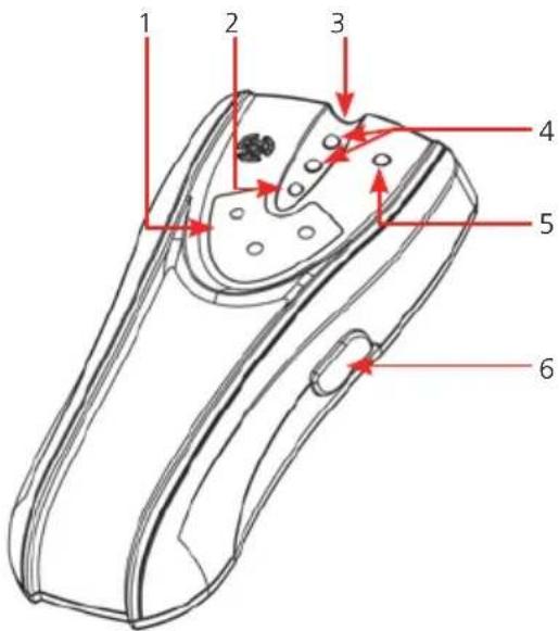
text_image
1 2 3 4 5 6| Item Description Item Description | ||
| 1 Range indicator 4 Stud detection LED | ||
| 2 Power LED 5 Live AC wire warning LED | ||
| 3 Depth range LEDs 6 ON/OFF button/range selection |
4. Operation
The MSL10 Stud Locator is designed to detect the presence of both wooden and metal studs or joists, as well as the presence of AC voltage, using a simple non-contact voltage detector.
WARNING: before using the non-contact voltage detection feature, make sure that the live AC cable warning LED is operating correctly. Check the locator on a known live AC cable (>110 V AC) and ensure the MSL10 live AC warning LED illuminates and the unit emits an audible sound. Shielded cables or cable in metal conduits, casings, metallised walls or thick dense walls will not be detected. AC power should always be turned off on all circuits within the area before drilling or excavation.
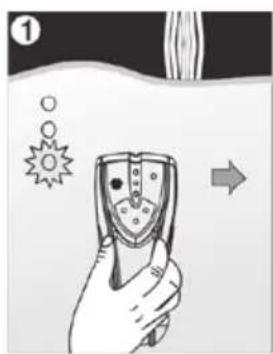
- Range Selection: Place the tester against the surface to be scanned. Click and hold ON/OFF button once for 12 mm range, the 12 mm range LED will illuminate. The detector will calibrate, followed by a beep and the power LED should remain on. Click twice and hold for 25 mm range and click 3 times and hold for 36 mm range, the corresponding LED of range indicator will illuminate, and then the detector will calibrate, followed by a beep and the working LED on.
- Hold the locator flat against the surface, making firm contact. Press and hold the ON/OFF button, the power LED will illuminate, along with the corresponding LED range indicator, and the locator will start its calibration process. When the detector is calibrated, the power LED, stud detection LED and live AC warning LED illuminate, the locator will beep once, then the stud detection LED and live AC warning LED will turn off. Keep holding the ON/OFF button during the whole measurement.
- Slide the locator slowly across the surface in a straight line. As it detects the edge of a stud or joist,, the two stud detection LED's will turn on and the locator will beep. Use the handy pencil notch located at the top of the locator to mark the stud edge.
- Move the locator to the other side of the stud or joist. Repeat steps 2 and 3 above to mark the other edge of the stud or joist. The midpoint of the two marks indicates the stud or joist centre.
natural_image
Illustration of a hand holding a handheld device with abstract symbols and an arrow indicating direction (no text or labels)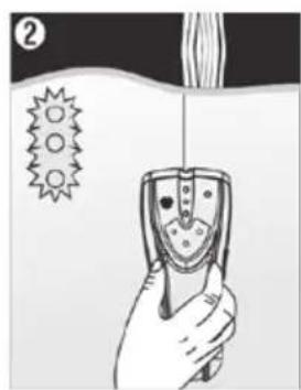
natural_image
Illustration of a hand holding a handheld device with a spike symbol nearby (no text or labels)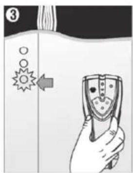
text_image
③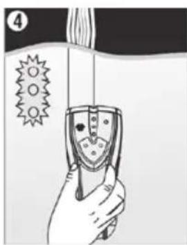
natural_image
Illustration of a hand holding a device with a spike symbol and a label '4' (no text or symbols on the device itself)NOTE : While calibrating, the detector must not be placed directly over a stud, dense material such as metal, or over a wet or newly painter area as this will cause the calibration process to fail. If this occurs, the two stud detection LED will flash quickly and the locator will beep rapidly. Move to a different location and recalibrate.
Tips of Operation
- Detecting Live AC cables: After calibration, move the locator across the area to be scanned, if it detects AC voltage within the defined detection range, the live AC wire warning LED will illuminate and the locator will beep rapidly. The MSL10 is designed to detect >100 V AC. It can also detect the presence of live wires which having greater voltage than 230 V AC.
- Low Battery Indication: Replace the battery if the green power LED is flashes when the locator power button is held down. When the battery is depleted, the locator will beep twice and the green power LED will go out. The battery must be replaced to restore operation. Replace the battery to restore operation.
5. Tips of Operation
The ON/OFF button must remain pressed during the entire search process. Repeat the scanning process several times to ensure the detection accuracy.
To ensure the vest performance from the MSL10, keep you free hand at least 150 mm away from the locator and do not place it on the wall surface. Failure to do this may interfere with the locators detection process.
Please note that cables can also be identified as a stud or joist. Depending on the depth of the cable, if it is live, the non-contact voltage detection may not indicate a live AC voltage. Extra care must be taken and all circuits isolated prior to drilling or excavation.
The locator will still operate on surfaces covered with fabric or wallpaper, unless the covering used contains metal foil or fibres.
When faced with a rough or uneven surface, a piece of thin card or paper can be placed on the surface and the locator used as normal. The calibration process described above should be carried out with the protective card or paper in place before starting the scan.
6. Maintenance.
NOTE : There are no user replaceable parts within this product, other than the battery cells and the fuses.
6.1 General maintenance
Ensure the unit is kept clean and dry.
Keep the locator in the protective carry pouch when not in use.
The locator should be checked for visible damage before each use.
6.2 Cleaning
Remove the battery before cleaning.
Wipe the instrument with a clean cloth dampened with either water or isopropyl alcohol (IPA).
6.3 Battery
CAUTION : Old batteries must be disposed of in accordance with local regulations.
CAUTION : Only use approved batteries as defined below.
The battery is easily accessible through the battery cover on the rear of the locator. The battery must be replaced as soon as the low battery warning appears, as described above.
Do not use rechargeable batteries in the MSL10.
To help maintain the health, reliability and longevity of the installed batteries:
Remove battery cells if the instrument is not going to be used for a long period.
Store batteries in a cool, dry place. Batteries can be damaged when exposed to heat.
7. Specifications
| Specification Detail | |
| Wood or Metal Studs 38 mm through plasterboard | |
| Live AC Wires (>110 V AC) 50 mm through plasterboard | |
| Operating Temperature 0 °C to 50 °C (32 °F to 122 °F) | |
| Storage Temperature -10 °C to 60 °C (14 °F to 140 °F) | |
| Power Source 9 V PP3/6LR61 | |
8. Calibration, Repair and Warranty
Megger operate fully traceable calibration and repair facilities to make sure your instrument continues to provide the high standard of performance and workmanship that is expected. These facilities are complemented by a worldwide network of approved repair and calibration companies, which offer excellent in-service care for your Megger products.
For service requirements for Megger instruments contact:
| Megger Limited | OR Megger GmbH |
| Archcliffe Road | Weststraße 59 |
| Dover | 52074 Aachen |
| Kent | Germany |
| CT17 9EN | Tel: +49 (0) 241 91380 500 |
| U. K. | |
| Tel: +44 (0) 1304 502 243 | |
| Fax: +44 (0) 1304 207 342 |
9. Decommissioning
9.1 WEEE Directive
The crossed out wheeled bin symbol placed on Megger products is a reminder not to dispose of the product at the end of its life with general waste.
Megger is registered in the UK as a Producer of Electrical and Electronic Equipment. The Registration No is WEE/HE0146QT.
For further information about disposal of the product consult your local Megger company or distributor or visit your local Megger website.
9.2 Battery disposal
The crossed out wheeled bin symbol placed on a battery is a reminder not to dispose of batteries with general waste when they reach the end of their usable life.
For disposal of batteries in other parts of the EU contact your local Megger branch or distributor.
Megger is registered in the UK as a producer of batteries (registration No.: BPRN00142).
For further information see www.megger.com
Local Sales office
Megger Limited
Archcliffe Road
Dover
Kent
CT17 9EN
ENGLAND
T.+44 (0)1 304 502101
F. +44 (0)1 304 207342
Manufacturing sites
| Megger Limited | Megger GmbH | Megger Valley Forge |
| Archcliffe Road | Weststraße 59 | 400 Opportunity Way |
| Dover | 52074 Aachen | Phoenixville, |
| Kent | GERMANY | PA 19460 |
| CT17 9EN | T. +49 (0) 241 91380 500 | USA |
| ENGLAND | E. info@megger.de | T. +1 610 676 8500 |
| T. +44 (0)1 304 502101 | F. +1 610 676 8610 | |
| F. +44 (0)1 304 207342 | ||
| Megger USA - Dallas | Megger AB | Megger USA - Fort Collins |
| 4545 West Davis Street | Rinkebyvägen 19, Box 724, SE-182 17 | 4812 McMurry Avenue |
| Dallas TX 75237 | Suite 100 | |
| USA | Danderyd | Fort Collins CO 80525 |
| T. 800 723 2861 (USA only) | SWEDEN | USA |
| T. +1 214 333 3201 | T. +46 08 510 195 00 | T. +1 970 282 1200 |
| F. +1 214 331 7399 | E. seinfo@megger.com | |
| E. USsales@megger.com |
This instrument is manufactured in the China.
The company reserves the right to change the specification or design without prior notice.
Megger is a registered trademark
MSL10_UG_en_V02 10 2022