
OCR15D - Measurement Megger - Free user manual and instructions
Find the device manual for free OCR15D Megger in PDF.

| Product Type | High Current Primary Injection Test Set |
| Model | OCR15D |
| Brand | Megger |
| Continuous Output Rating | 15 kVA |
| Input Voltage Range | 120-480 VAC, single-phase (selectable via terminal board) |
| Output Current Range | Up to 2000 A (depending on tap and impedance) |
| Output Voltage Taps | Multiple taps for various current/voltage combinations |
| Measurement Ranges | 20 A, 200 A, 2 kA, 20 kA full scale |
| Display | Touch screen, microprocessor-controlled |
| Timing Resolution | 0.1 cycle (typical) |
| Test Capabilities | Minimum pick-up, timing, multiple shot sequences for reclosers and sectionalizers |
| Safety Features | Emergency stop, safety interlock footswitch, ground fault alarm |
| Weight | Approximately 300 lb (136 kg) |
| Dimensions (H x W x D) | 36 x 24 x 24 in (914 x 610 x 610 mm) |
| Cooling | Forced air (fan) |
| Operating Temperature | 0-50 °C (32-122 °F) |
| Warranty | Standard Megger warranty (typically 1 year) |
| Compliance | CE, safety standards per IEC 61010 |
Frequently Asked Questions - OCR15D Megger
User questions about OCR15D Megger
0 question about this device. Answer the ones you know or ask your own.
Ask a new question about this device
Download the instructions for your Measurement in PDF format for free! Find your manual OCR15D - Megger and take your electronic device back in hand. On this page are published all the documents necessary for the use of your device. OCR15D by Megger.
USER MANUAL OCR15D Megger
It is essential that this instruction book be read thoroughly before putting the equipment in service.
Revision History
| Revision | ECN # | Date |
| 1 | 33728 | 6 Nov 2019 |
IMPORTANT
This manual, as well as the hardware and software described in it, is furnished under license and may be used or copied only in accordance with the terms of such license. The content of this manual is furnished for informational use only, is subject to change without notice. Megger assumes no responsibility or liability for any errors or inaccuracies that may appear in this manual.
The information and data in this User Manual are proprietary. The equipment described herein may be protected by U.S. patents. Megger specifically reserves all rights to such proprietary information as well as rights under any patent, none of which is waived by the submission of this user manual.
Except as permitted by such license, no part of this publication may be reproduced, stored in a retrieval system, or transmitted, in any form or by any means, electronic, mechanical, recording, or otherwise, without the prior written permission of Megger.
Megger, the Megger logo are trademarks of Megger. All other trademarks are the property of their respective owners.
Notice to U.S. government end users. The hardware, software and documentation are “commercial items”, as that term is defined at 48 C.F.R. §2.101, consisting of “commercial computer software” and “commercial computer software documentation,” as such terms are used in 48 C.F.R. §12.212 or 48 C.F.R. §227.7202, as applicable. Consistent with 48 C.F.R. §12.212 or 48 C.F.R. §§227.7202-1 through 227.7202-4, as applicable, the commercial computer software and commercial computer software documentation are being licensed to U.S. government end users (1) only as commercial items and (2) with only those rights as are granted to all other end users pursuant to the terms and conditions set forth in the Megger standard commercial agreement for this software and hardware. Unpublished rights reserved under the copyright laws of the United States. The recipient, if a Government agency, acknowledges that this manual and the equipment described were procured with "Limited Rights" to technical data as described in ASPR 9-203 (b).
The STVI includes an RTOS-resident computer program. This program belongs to Megger and contains trade secret ideas and information of Megger.
Written and designed at Megger, 4271 Bronze Way, Dallas, Texas 75237.
Printed in the USA.
© 2011 Megger, all rights reserved.
SAFETY PRECAUTIONS
WARNING:
VOLTAGES GENERATED BY THIS INSTRUMENT CAN BE HAZARDOUS
This instrument has been designed for operator safety; however, no design can completely protect against incorrect use. Electrical circuits are dangerous and can be lethal when lack of caution and poor safety practices are used. There are several standard safety precautions that should be taken by the operator. Where applicable, IEC safety markings have been placed on the instrument to notify the operator to refer to the user manual for instructions on correct use or safety related topics. Refer to the following table of symbols and definitions.
| Symbol | Descripon |
 | Direct Current |
 | Alternating Current |
 | Both direct and alternating current |
 | Earth (ground) Terminal. There is a common chassis ground terminal located on the front panel (see Front panel under Description of Controls. |
| [4HWS] | Protective Conductor Terminal |
 | Frame or Chassis Terminal |
 | On (Supply) |
 | Off (Supply) |
 | Caution, risk of electric shock |
 | Caution (refer to accompanying documents) |
WARNING: Under no circumstances should the operator or technician attempt to open or service any Megger instrument while connected to a power source. Lethal voltages are present and may cause serious injury or death!
SAFETY PRECAUTIONS (Continued)
The following are some specific safety related items associated with the OCR test systems.
Read and understand all safety precautions and operation instructions before attempting to use this unit.
This test set should only be operated by specifically trained technicians and engineers familiar with this type of industrial electrical equipment.
The purpose of this equipment is limited to use as described in this instruction manual. Should a situation arise that is not covered in the general or specific safety precaution please contact Megger regional representative or Megger, Dallas Texas.
Safety is the responsibility of the user. Misuse of this equipment can be extremely dangerous.
Always start with the main power OFF, before connecting the power source. Make sure outputs are off before attempting to make test connections.
Never connect the test set to energized equipment.
Always use properly insulated test leads. The optional test leads are rated for the continuous output ratings of the test system, and should be properly used and cared for. DO NOT use cracked or broken test leads.
Always turn the test system off before disconnecting the power cord.
DO NOT attempt to use the unit without a safety ground connected.
DO NOT attempt to use the unit if the power cord ground prong is broken or missing.
DO NOT use the test set in an explosive atmosphere.
The instrument must only be used by suitably trained and competent persons.
Observe all safety warnings marked on the equipment.
For safety related or other important topics, like the statement below, will be notated with the adjoined symbol. Read the topic carefully as it may relate either to the safe operation of the test system or the safety of the operator.

Under no circumstances should the operator put their hand or tools inside the test system chassis area with the test system connected to a power source. Lethal voltages are present and may cause serious injury or death!
This test set includes a resident computer program.
This program belongs to Megger and contains trade secret ideas and information of Megger.
To the extent this program contains ideas, Megger intends to protect and enforce it rights under state law. To the extent the program is deemed to constitute a form of expression of an idea, Megger intends to protect and enforce its rights under the Copyright Act of 1976. The Statutory Copyright notice has been affixed hereto in the event that it is later determined that the program has been published within the meaning of the Copyright Act of 1976.
It is essential that this instruction book be read thoroughly before putting the equipment in service.
TABLE OF CONTENTS
I. General Description
II. Safety Precautions
III. Input Circuit
IV. Output Circuit
V. Description of Controls
VI. Test Procedures
A. Series Type Reclosers
-
Minimum Pick-up Test
-
Timing Test
B. Testing Vacuum Type Reclosers
C. Reclosers Requiring Line Voltage for Closing
D. Sectionalizers
I. GENERAL DESCRIPTION
The Megger Model OCR15D and OCR50D are high current primary injection test sets designed for testing automatic oil and vacuum circuit reclosers and other current actuated devices. These units incorporate a variable high current ac output with an impedance matching network to stabilize the output current. The unit provides appropriate instrumentation and control circuitry to monitor contact closure, opening and provide timing functions.
II. SAFETY PRECAUTIONS
WARNING

Potentially lethal voltages can be present on the output leads when the test set is in operation. The operator is responsible for ensuring the safety of all personnel during operations. While conducting tests, keep all personnel at a safe distance from the test set and the device being tested.

CAUTION
For safety of the operator, it is absolutely essential that the test set be properly and effectively grounded.
III. INPUT CIRCUIT
INPUT VOLTAGE
OCR50D
Due to the output capability (50 kVA continuous for the OCR50D) as well as the specific applications for which the test set was designed, the test set must be powered by a 480 volt single-phase input service.
OCR15D
The Megger OCR15D (15 kVA continuous) is designed to operate from any of several input voltages in order to accommodate the various voltages encountered by users in the field. It is necessary to change the input terminal connections to match the available input voltage. This change is made on a terminal board located inside the right side access panel. The test set must be disconnected from the supply source before attempting to change the terminals.
SELECTION OF INPUT LEADS
Due to the wide variation in individual user requirements with regard to wire sizes, terminations and length of leads, all units are supplied with input socket and matching plug only. The plug will accept a wide range of wire sizes more than adequate for the duty required. The power source must have sufficient capacity, and the input leads must be large enough to maintain RATED input voltage at the INPUT terminals of the test set. Although the test set is designed to operate satisfactorily at 95-105% of rated voltage, any drop in voltage below RATED at the input terminals will result in a proportional decrease in the maximum available output.
NOTE: To achieve published output currents, the rated input voltage must be maintained at the test set terminals during the test.
When utilizing maximum output from the test set, the input line currents may be as high as 400% of nameplate rating. The following table has been prepared to aid in selecting the proper wire size for the input leads. To use the table, refer to the following four steps:
- Determine the rated input current from the nameplate on the test set. Be sure to choose the correct current for the input voltage being used.
- Multiply this value by four.
- Determine the length of input lead required. This is in circuit-feet, therefore it is the one-way distance from the test set to the power source.
- Select the proper wire size from the table using factors 2 and 3 above.
Input Lead Example:
Step 1 - 100 amperes (from nameplate)
Step 2 - 4 x 100 = 400 amperes
Step 3 - 60 ft. (distance from test to input power source.)
Step 4 - # 2 wire (from Chart)

For safety, a ground wire must be connected to the test set frame. The size of this conductor should be not less than 1/2 the cross section of the current carrying input leads (three-wire sizes less) and in no event smaller than #10. An audible alarm is sounded if the test set is not properly grounded.
SELECTOR CHART FOR INPUT LEADS
LENGTH OF INPUT LEADS
DISTANCE FROM TEST SET TO POWER SOURCE
FOUR TIMES (4X)
RATED INPUT POWER 20 40 60 80 100 120 140 FEET
MINIMUM WIRE SIZE A. W. G.
| 50 | 8 | 8 | 8 | 8 | 8 | 8 | 8 |
| 75 | 8 | 8 | 8 | 8 | 8 | 8 | 6 |
| 100 | 8 | 8 | 8 | 8 | 6 | 6 | 4 |
| 125 | 8 | 8 | 8 | 6 | 6 | 4 | 4 |
| 150 | 8 | 8 | 8 | 6 | 4 | 4 | 2 |
| 175 | 8 | 8 | 6 | 4 | 4 | 2 | 2 |
| 200 | 8 | 8 | 6 | 4 | 4 | 2 | 2 |
| 225 | 8 | 8 | 6 | 4 | 2 | 2 | 1 |
| 250 | 8 | 6 | 4 | 4 | 2 | 2 | 1 |
| 275 | 8 | 6 | 4 | 2 | 2 | 1 | 1/0 |
| 300 | 8 | 6 | 4 | 2 | 2 | 1 | 1/0 |
| 325 | 8 | 6 | 4 | 2 | 1 | 1 | 2/0 |
| 350 | 8 | 4 | 2 | 2 | 1 | 1/0 | 2/0 |
| 375 | 8 | 4 | 2 | 2 | 1/0 | 2/0 | 2/0 |
| 400 | 8 | 4 | 2 | 1 | 1/0 | 2/0 | |
| 425 | 8 | 4 | 2 | 1 | 1/0 | 2/0 | |
| 450 | 8 | 4 | 2 | 1 | 2/0 | ||
| 475 | 6 | 4 | 2 | 1/0 | 2/0 | ||
| 500 | 6 | 4 | 2 | 1/0 | 2/0 | ||
| 525 | 6 | 2 | 1 | 1/0 | 2/0 | ||
| 550 | 6 | 2 | 1 | 1/0 | |||
| 575 | 6 | 2 | 1 | 2/0 | |||
| 600 | 6 | 2 | 1 | 2/0 |
THE WIRE SIZES IN THIS CHART WILL RESULT IN VOLTAGE DROPS OF 10 VOLTS OR LESS.
IV. OUTPUT CIRCUIT
SELECTION OF OUTPUT TERMINAL
Several output terminals at various voltage and current ratings are provided to adapt the OCR Test Set to a wide variety of test circuit impedances. The current ratings shown on the output taps are the continuous duty ratings. The test set works at peak efficiency when the outputs are used at 2 to 3 times their continuous rating. In this way, finer adjustment can be obtained by making maximum use of the variable autotransformer range and matching impedance network. The LOW CURRENT terminals should be used when testing high impedance devices where higher current terminals do not have sufficient voltage to "push" the desired test current through the device. For example, to test a recloser with a 50 amp coil rating at a test multiple of 5x (250 amperes), the operator should use the 100A output tap (not the 250A tap). Only when the test current exceeds 300A should the 250A tap be used.
SELECTION OF COMMON TERMINALS
The ammeter circuit of the OCR test set utilizes two current transducers to measure both the very low and high currents available from this unit. For the ammeter to correctly measure the output current of the test set, the proper common terminal must be selected. For currents of 20 amperes and below, COMMON 1 Terminal must be used; and, similarly, when test currents exceed 20 amperes, COMMON 2 Terminal must be used.
SELECTION OF MATCHING IMPEDANCE
The impedance matching network is incorporated to swamp-out the changing impedance of the recloser. As the operating plunger moves through the coil of the recloser the impedance increases. Experience has shown that the higher the matching impedance on the primary of the output transformer, the less effect the changing impedance of the recloser has on the output current. The limiting factor is the available power of the test set. The more matching impedance, means more power consumed by the test set and less available output current. To select the appropriate matching impedance to conduct timing tests, first select the appropriate output tap and common, i.e. for a test current of 200 amperes use the 150V-100A tap (see SELECTION OF OUTPUT TERMINAL). The appropriate matching impedance for a given recloser will be determined through experience. Until such time, move the impedance tap selector switch to position 10. Rotate the Output Control wheel to the 90% position.
Upon operation of the test set, in the momentary position, if the test current indicated is too low, switch the LOAD COMPENSATOR Switch to position 11 and repeat the procedure. Switching to position 11 decreased the matching impedance and therefore allows more output test current. If the test current is too high, switch the impedance tap selector switch to position 9 to increase the matching impedance, thus reducing the output test current and repeat the procedure. Fine adjustment of the current can be made with the Output Control wheel.
It is suggested that the LOAD COMPENSATOR switch never be moved to position # 15 during a recloser timing test. The lack of any matching impedance could result in inaccurate results and possible damage to the test set.
OUTPUT CONNECTIONS
The testing of devices requires the use of test leads for connections between the test set and the device being tested. The following information on the selection of output leads will provide the user with a guide for choosing the proper tests leads for this application.
Due to the voltage drop from the inductive reactance of the test circuit, a significant loss of current will result for each inch of test lead. Therefore, when choosing test leads, the length and size of lead chosen will determine the maximum available test current. It is worthwhile to sacrifice cross section of test leads for the sake of reducing length. Every inch of lead that can be eliminated provides worthwhile increase in available test current. Heating is not a significant problem in testing, even though the leads can become hot. The use of 4/0 welding or motion picture cable is convenient for constructing test leads. Paralleling of sufficient cables provides higher test currents. Each cable can be fitted with a compression lug on each end, then bolted to the output terminals of the test set and the breaker.
The two cables between the test set and the device under test should be twisted together or bundled with tape or cord to maintain the close proximity which minimizes inductive reactance.
V. DESCRIPTION OF CONTROLS
This section of the instruction manual describes the function of the various controls located on the Megger Model OCR50D. The OCR15D is similar (no indicator lamps or switch on the left side of the front panel). The majority of controls are located on the touch sensitive control panel. The controls are easily accessed via icons on the screen and provide for easy operation after a minimum of operator familiarity. Figure 1 shows the location of the front controls.

Figure 1 – Front Panel Controls
Along the right side of the control panel are the:
Output Engizered Lamp – illuminates when the output is energized
Emergency Stop (ESTOP) Switch – pressing this button stops any testing
Adjustment Knob - this knob can take on various functions in the software.
The external connections are located to the left of the touch panel.
The USB connectors provide the ability to: attach a USB thumb drive (for exporting test reports or updating firmware/software), attach an external mouse or to attach a USB keyboard.
The USB "B" connector (center connector) allows the user to connect an external PC.
The switch at the bottom left is used to direct control to either the “onboard” (internal) computer or a “remote” (external) computer.
The touch panel provides the main OCR control capability via the OCR application in the PowerDB software. The OCR test set wakes to the OCR main screen when powered up.
MICROPROCESSOR-CONTROLLED OPERATION
The microprocessor based control and instrumentation system ensures simple operation and precise test results. The software automatically detects the minimum pick-up current. It will signal when minimum pick-up is achieved and display the magnitude of the pick-up current. The software records the current magnitude, trip time and reclose times for each operation of the recloser. The software will also indicate if the recloser took excessive shots to lock-out. Additionally, the software will de-initiate the test set if the recloser is exceeding the allowed time to lock-out and will indicate to the operator excess time to lock-out. The software is also programmed to detect errors associated with operation of the test set or the device under test.
OCR Main Screen
Below is the OCR main test screen. The menu icons are shown across the top of the screen.

Figure 2 – OCR Main Screen
The menu icons (across the top of the screen):

Connection Indicator – indicates the connection status of the controller
Configuration Screen – select frequency and software data logging
Clear Test Results – select to clear test result or clear all test results
Scale Selection – select full scale current (20A, 200A, 2kA, or 20kA – defaults to 200A)

View Test Report – view the present test report
Add Test to Report – add the current test data and open the test report
File Operations – controls for saving/opening/deleting files
Nameplate Information – allows entry of pertinent nameplate information
Timer Setup – allows selection of timer control to follow current flow or a contact
Test Selection – allows the user to select a test to run
Help – online help
Configuration Screen
This menu item allows the user to set the OCR configuration parameters. Press the green check button when finished.
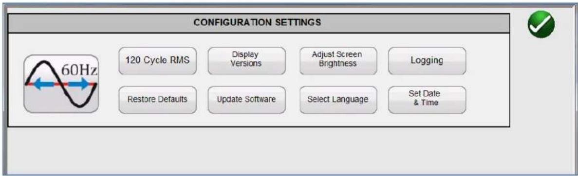
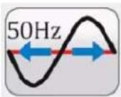
Frequency - allows the user to toggle between 50/60 Hz system frequency:

RMS Measurement Mode - allows selection of RMS measurement modes
120 Cycle RMS
4 Cycle RMS
The 120 Cycle RMS mode will use up to 120 cycles of data to determine the RMS measurement. The 4 Cycle RMS mode will utilize the last 4 cycles of data for calculations.
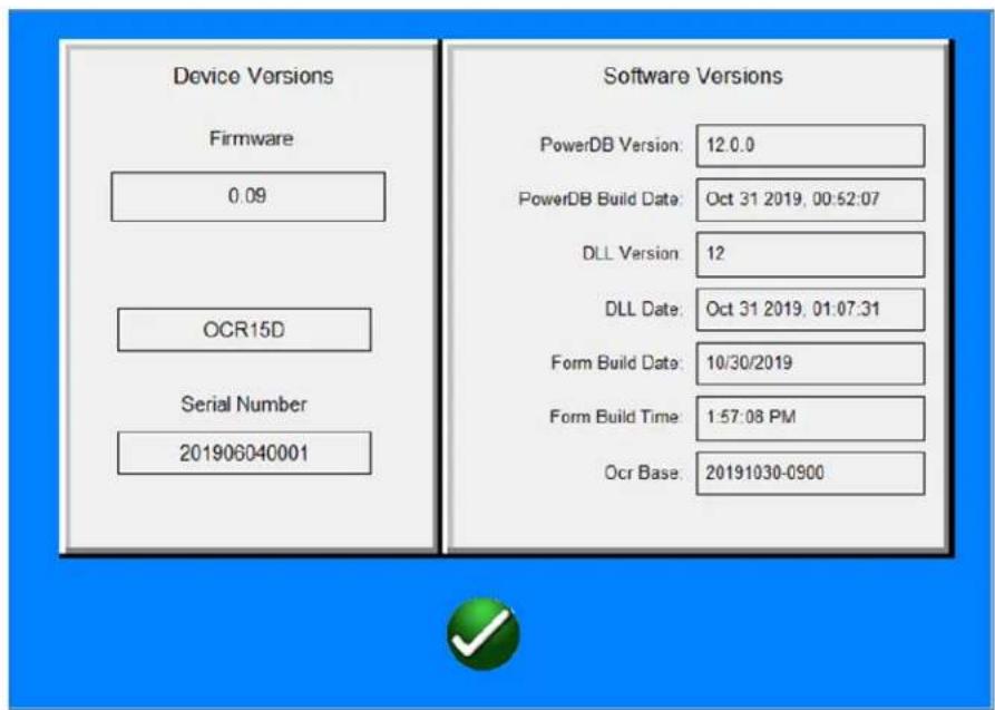
Display Versions – Displays the hardware and software version information:
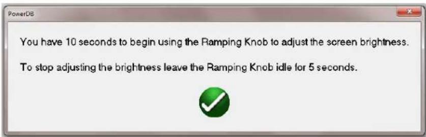
Adjust Screen Brightness - Allows the user to adjust screen brightness using the black control knob to the right of the touch screen:
Logging - controls for enabling, clearing and copying the system log files (to a USB stick):
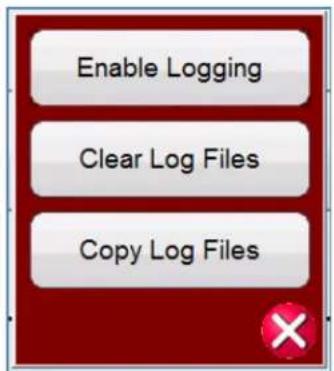
“Enable logging” activates the software logging function.
"Clear log files" deletes the existing content of the log files.
"Copy log files" copies the log files to a USB stick.
Note that default is logging disabled. The user must enable logging to capture log files. It is suggested that the log files be cleared prior to enabling the logging.
Log files are used for trouble-shooting and monitoring software operations. Log files may be requested by support personnel to help address any issues.
Restore Defaults – Restores parameters to factory settings:

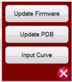
Update Software – Allows for PowerDB software or OCR Firmware updates and adding curve library updates:
Select Language – Allows for language selection

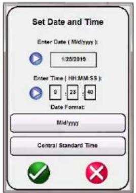
Set Date & Time - Allows the user to set date and time:
Clear Test Results
This menu allows the user to clear test results:

Scale Selection
This menu allows the user to select the full-scale metering range. Default selection is the 200A range.

View Test Report
This menu allows the user to review the present Test Report. Press the green check button when finished.

Add to Test Report
This menu allows the user to add the present Test data to the Test Report. The current test results will be added and the Test Report and displayed. Press the green check button when finished.
File Operations
This set of controls allows the user to open a new form, Open an existing record, Save the current form, open the Configuration screen or return to the main screen.

Nameplate Information

Note that items shown in blue may be toggled for the selection of alternate units.
The "RECLOSER" button may be pressed to access the "SECTIONALIZER" test.

The “SECTIONALIZER” selection allows access to a pre-programmed test for sectionalizer testing. The data needed for this testing is the “Number of Shots”, the “On Time” and the “Off Time”. This function will apply the manually selected current to a sectionalizer for the specified On/Off times and monitor the sectionalizer to determine if it opens after the specified number of applied shots.
Timer Setup

Timer follows current flow. Timer starts/stops with current flow.
Timer follows a normally open contact (contact closure stops the timer.
Timer follows a normally closed contact (contact opening stops the timer).
Close the Timer setup.
Test Selection
This menu allows the user to select one of the configured tests for the OCR.

Online Help
This menu provides access to the Quick Start Help or Full Help.

VI. TEST PROCEDURES
SERIES TYPE RECLOSERS
MINIMUM PICK-UP TEST
- Connect output of test set to OCR under test. To save time, select an output tap which coincides with the desired test current used in the TIMING TEST (see SELECTION OF OUTPUT TERMINAL on page 5).
- Turn input power to test set ON, allow 1 to 2 minutes for the digital instruments to power up.
- Select the proper AMMETER RANGE which will allow measurement of 2 times coil rating of recloser under test. (Example: OCR with 35A coil should have 70A pickup, therefore select 200A range.)
- Select the Nameplate menu and enter the appropriate data to define the OCR (manufacturer, model, coil size, TCC's and number of timing tests). The number of timing tests defines the number of different current multiples for time testing (example: 1.5X, 3X, etc.).
- Select the Pickup Test from the test menu. Note that the mode is showing "continuous". Step on the safety interlock footswitch and press the START button.
- Increase output control in a clockwise direction. The CURRENT meter should begin to indicate current flow. Continue to increase output current until the OCR operates. Then decrease the output control to zero.
- Step off the safety interlock footswitch. You can read the minimum pickup current on test report screen.
NOTE: Rotating the output control too slowly may induce error into the detection of pickup by the microprocessor.
TIMING TEST
- Determine test current to be applied to OCR under test. This is usually 4 to 6 times coil rating. (Example: 35A coil tested at 4 times would require 140 amps.)
- Select appropriate ammeter range.
- Use LOAD COMPENSATOR Switch to adjust impedance network. (See Selection of Matching Impedance page 13.)
- Select the Timing test from the Test Selection menu.
- To set test current prior to running timing test, the output is momentarily initiated, the current is read on the ammeter and the output control is then readjusted.
This is done by stepping on the footswitch and then alternately increasing output control in clockwise direction and momentarily pressing the START Pushbutton. The test set will initiate for the set time allowing the user to set the current amplitude. Observe the CURRENT Display. Repeat initiating output and increasing output control until the proper current value is obtained. Step off the foot switch. - Select the OCR TIMING button. Select the Timing Test you wish to run. Multiple timing tests will be shown if you have defined more than one current multiple for time testing.
- Be sure to allow the OCR time to completely reset before initiating the timing test.
- Step on the safety footswitch and press the START Pushbutton. Current will flow in the OCR under test and it will begin its sequence of operations. The OUTPUT ENERGIZED Indicator will be illuminated. The control unit will indicate each operation. At the end of the test interval the test set will de-initiate. The user may see various test messages:
A. BREAKER IS NOT CLOSED OR CURRENT OUTPUT IS TOO LOW
This indicates the OCR under test Is either not closed or the test current is too low.
B. TEST FAILED WITH TOO MANY TRIPS
This indicates that the OCR under test has operated more than the programmed number of operations.
C. TEST FAILED WITH TOO FEW TRIPS
This indicates that the OCR under test has operated less than the programmed number of operations.
- At the completion of the test the "OUTPUT ENERGIZED" indicator will be extinguished. At this point the operator can release the safety footswitch.
- The user may add the test results to the test report by selecting the "Add to Report" button. The results of the test can then be viewed in the test report.
TESTING VACUUM TYPE RECLOSERS
Most vacuum reclosers test the same as a series type oil circuit reclosers. The same test procedure may be used to test vacuum reclosers. It must be noted that the contacts used in vacuum reclosers tend to bounce, which can cause timing errors and may also be interpreted by the microprocessor as an excess shot. When testing vacuum reclosers, if an abnormally fast trip time is indicated this could indicate contact bounce has occurred. When this occurs, it may be desirable to retest the recloser. The microprocessor is programmed to ignore contact bounce. If the problem persists, inspect the recloser for possible internal problems.
RECLOSERS REQUIRING LINE VOLTAGE FOR CLOSING
It is recommended that reclosers which require line voltage for closing be tested using one of the previous procedures and manually closed after each operation. This procedure will verify the time current operation and avoids the danger of having high voltage in the test area. The recloser must be manually closed within a few seconds after operation in order to establish a normal sequence of operation (prevent the recloser from resetting).
However, if testing with line voltage is required, connect the OCR test set to "A-O" of the recloser, and connect the high voltage source to "B" and "C" phases.
WARNING
Do not connect the high voltage source to the same phase that the OCR test set is connected.
Perform pick-up and timing tests the same as a series type recloser. To perform tests to B and C phases will require manually reclosing as previously discussed above.
SECTIONALIZER TESTING
Sectionalizers are not typically intended to be fault current interrupting devices. They are devices that count the interruption of current on a monitored line and will operate after they have detected a pre-set number of trips (shots) within prescribed times. They are usually set between 1 and 3 shots. They usually work in conjunction with a recloser and are intended to isolate a line section after a fixed number of trips so as not to interrupt the entire amount of load serviced by the recloser. Testing will require the user to manually set the test current amplitude, enter the number of shots, the current “ON” times and the current “OFF” times. The pre-programmed test will apply the current pulses for the specified times and monitor the sectionalizer response for proper operation.
- IMPORTANT
- SAFETY PRECAUTIONS
- WARNING:
- VOLTAGES GENERATED BY THIS INSTRUMENT CAN BE HAZARDOUS
- SAFETY PRECAUTIONS (Continued)
- TABLE OF CONTENTS
- GENERAL DESCRIPTION
- SAFETY PRECAUTIONS
- WARNING
- CAUTION
- INPUT CIRCUIT
- INPUT VOLTAGE
- OCR50D
- OCR15D
- SELECTION OF INPUT LEADS
- SELECTOR CHART FOR INPUT LEADS
- OUTPUT CIRCUIT
- SELECTION OF OUTPUT TERMINAL
- SELECTION OF COMMON TERMINALS
- SELECTION OF MATCHING IMPEDANCE
- OUTPUT CONNECTIONS
- DESCRIPTION OF CONTROLS
- MICROPROCESSOR-CONTROLLED OPERATION
- OCR Main Screen
- Configuration Screen
- RMS Measurement Mode - allows selection of RMS measurement modes
- Display Versions – Displays the hardware and software version information:
- Set Date & Time - Allows the user to set date and time:
- Clear Test Results
- Scale Selection
- View Test Report
- Add to Test Report
- File Operations
- Nameplate Information
- Timer Setup
- Test Selection
- Online Help
- TEST PROCEDURES
- SERIES TYPE RECLOSERS
- MINIMUM PICK-UP TEST
- TIMING TEST
- BREAKER IS NOT CLOSED OR CURRENT OUTPUT IS TOO LOW
- TEST FAILED WITH TOO MANY TRIPS
- TEST FAILED WITH TOO FEW TRIPS
- TESTING VACUUM TYPE RECLOSERS
- RECLOSERS REQUIRING LINE VOLTAGE FOR CLOSING
- SECTIONALIZER TESTING
Brand : Megger
Model : OCR15D
Category : Measurement