
FY-AC-STD-SPP - Household Fan PANASONIC - Free user manual and instructions
Find the device manual for free FY-AC-STD-SPP PANASONIC in PDF.


| Product Type | Domestic Fan |
| Brand | Panasonic |
| Model | FY-AC-STD-SPP |
| Fan Diameter | Approx. 40 cm (16 inches) |
| Dimensions (W x H x D) | Approx. 450 x 1300 x 450 mm (with stand) |
| Net Weight | Approx. 4.5 kg |
| Power Supply | 220-240 V ~ 50/60 Hz |
| Power Consumption | Approx. 45 W |
| Airflow Speed Settings | 3 speeds (Low, Medium, High) |
| Oscillation | Yes, wide-angle oscillation |
| Timer | Yes, 1-8 hours |
| Remote Control | Yes, included |
| Control Type | Remote control and touch panel on base |
| Blade Material | ABS plastic |
| Grille Material | ABS plastic |
| Stand Material | Steel with plastic base |
| Adjustable Height | Yes, telescopic stand |
| Tilt Adjustment | Yes, manual tilt |
| Safety Features | Overheat protection, tip-over switch |
| Cleaning | Wipe with soft damp cloth; do not immerse in water |
| Spare Parts Availability | Replacement blades, grille, remote, and stand available via Panasonic service centers |
| Warranty | 2 years (depending on region) |
| Repairability Index | 7.0 / 10 (based on spare parts availability and design) |
Frequently Asked Questions - FY-AC-STD-SPP PANASONIC
User questions about FY-AC-STD-SPP PANASONIC
0 question about this device. Answer the ones you know or ask your own.
Ask a new question about this device
Download the instructions for your Household Fan in PDF format for free! Find your manual FY-AC-STD-SPP - PANASONIC and take your electronic device back in hand. On this page are published all the documents necessary for the use of your device. FY-AC-STD-SPP by PANASONIC.
USER MANUAL FY-AC-STD-SPP PANASONIC
natural_image
Technical line drawing of a rectangular duct or duct with internal metal framework (no text or symbols)Panasonic®
INSTALLATION AND OPERATING INSTRUCTIONS
HUỐNG DÂN LẮP ĐẶT
VÀ SỬ DỤNG
Air Curtain
QUAT CHĂN GIÓ
Model No. Model
| FY-3509U1 FY-3512U1 |
| FY-4009U1 FY-4012U1 |
Contents
Safety instructions 2
Installation cautions....2\~3
Supplied accessories 4
Parts name and dimensions ..... 4
Requirement of installation......5
How to install ......6\~7
Multiple products operate in group....8
Wiring diagram....8
Operation methods....8 \~9
Routine maintenance ..... 10\~11
Trouble shooting.... 12
Specifications....13
Nội dung
Thank you for purchasing this Panasonic product.
Please read these installation and operating instructions carefully before attempting to install, operate or service the Panasonic product. Please carefully read the "Installation cautions" (P.2\~3) of this installation and operating instructions before installation. Failure to comply with installation and operating instructions could result in personal injury or property damage. Please explain to users how to operate and maintain the product after installation, and this booklet should be presented to users. Please retain this booklet for future reference.
Please observe strictly

■ If the supply cord is damaged, it must be replaced by the manufacturer, its service agent or similarly qualified persons in order to avoid a hazard.
This product is not intended for use by persons (including children) with reduced physical, sensory or mental capabilities, or lack of experience and knowledge, unless they have been given supervision or instruction concerning use of the product by a person responsible for their safety.
■Children should be supervised to ensure that they do not play with the product.
■Make sure to disconnect the power supply before cleaning the product.
The following explanations must always be observed in order to prevent harm to users or other people and prevent damage to property.
■The following displays are classified and explained to what extent harm or damage occurs when the display details are ignored and the unit in question is wrongly used.

WARNING
This indication means: Must be treated seriously that this may result in death or serious injury.

CAUTION
This indication means: Must be treated seriously that this may result in injury or property damage.
■The types of details to be observed are classified and explained in the following illustrated displays. (Below are the series of illustrated displays)


This symbol indicates the "COMPULSORY" item that must be followed without failure.


This symbol indicates the item "PROHIBITED" to do.
Installation cautions

WARNING
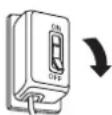
■Please install an all-pole switch which the contact separation is more than 3mm (Double pole switch).

Otherwise, it may cause a short circuit, thus resulting a fire.
■Do not operate the product other than the rated voltage.

Otherwise, it may damage the product or cause fire.
■The product must be grounded.

Otherwise, it may cause electric shock when there is any trouble or electric leakage.
■Wiring should be firmly connected without any loose.

Otherwise, it may cause a short circuit, thus resulting a fire.
■Installation should be done by authorized person. The product should be installed firmly.

Otherwise, the product may fall down and it may cause injury.
■Do not reconstruct this product.

Otherwise, it may cause damage to the product or injury.
Installation cautions

WARNING
■The product must be installed tightly. Components must be installed tightly.

Otherwise, it may injury person caused by product's falling off.
■Do not install the product as the method which is not approved in the installation and operating instructions.

Otherwise, the product any fall down and it may cause injury.
- It's prohibited to install the product in locations such as machinery, chemical plants or research facilities where it will be exposed to noxious gases containing acids, alkali, organic solvents, paint fumes, etc., to gases containing corrosive ingredients.

It could cause gas poisoning, corrosion and degradation of product that results in a fire.
■It's prohibited to install in the following locations.
Do not install the product where there is steam.


Otherwise, it may cause a short circuit, thus resulting in a fire.
Location with combustible gas or emission of exhaust gas.

Otherwise, it may cause a short circuit, thus resulting in a fire.
Do not install the product out of the window and wall.

Indoor Outdoor

Otherwise, the product may get wet in the rain and cause a short circuit.

CAUTION
■Product must be installed by 2 persons.


Otherwise, the product may fall down and it may cause injury.
■The special-purpose or dedicated parts, such as mounting fixtures, must be used if such parts are provided.

Otherwise, the product may fall down and it may cause injury.
■The product must be mounted on a building which is strong enough. To ensure it can bear over 5 times of product weight. The building must be reinforced if its strength can not be ensured.


Otherwise, the product may fall down and it may cause injury.
■Please wear the gloves when installing the product.


Otherwise, it may cause damage.
Supplied accessories
The following attachments are enclosed in the packing box of product. Be sure to check if they are complete after unpacking, and if anything is missed, contact our After-Sales Service Center or the dealer.
| No. | Drawing Name | Quantity | No. Drawing | Name Quantity | ||
| 1 | [4YDS] | Washer 6 | 4 |  | Bolt M8×60L 6 | |
| 2 |  | Spring washer | 6 | 5 | [50H7] | Installation and operating instructions |
| 3 |  | Nut (M8) | 6 | 6 |  | Service parts list |
Parts name and dimensions
■Front view

■Back view

(Φ8mm wooden screws are used)
■Right view
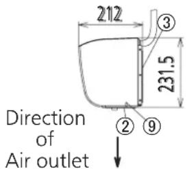
| Model No. | A | B |
| FY-3509U1, FY-4009U1 | 900 | 50 |
| FY-3512U1, FY-4012U1 | 1200 | 200 |
| No. | Part name | Classification | No. | Part name | Classification |
| 1 | Front panel | Resin ABS | 6 | Motor support | Steel SGCC |
| 2 | Air outlet Resin ABS | 7 | Cross-flow impeller | Steel plate + ResinAS + Glass fiber | |
| 3 | Mounting plate | Steel SGCC | |||
| 4 | Back panel | Steel SGCC | 8 | Push-button switch | Assembly part |
| 5 | Motor | Assembly part | 9 | Guide plate | Resin ABS |
Notice
Please refer to the table above to recycle the materials as much as possible when discarding this product.
Requirement of installation
■ Please observe the following requirement. Otherwise, it may cause the product aging and breakdown.
The applicable ambient temperature of this product is in the range of -10^ 40^ .


Do not install the product where it is exposed to oil fumes.

natural_image
Illustration of a steaming hot pot with a lid and a crossed-out 'X' symbol (no text or labels)It's prohibited to install in the uneven surface. (Flatness shall be 3mm below.)
Distortion results in reducing the separation performance.
Locations where freezing could happen.
Otherwise, it may damage the product or cause fire.
Do not install the product in the place with many dust.
Impeller deformation may be caused by sand and dust piling up, which may affect the performance.
■The lowest surface of this product should be installed above 2.3m from the floor after installation.
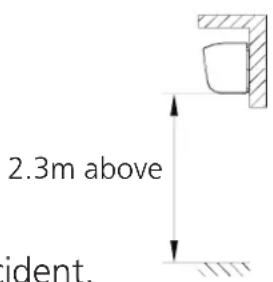
Avoiding any accident.
- Please install the product horizontally, don't vertically install the product.
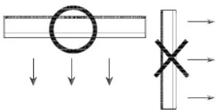
It could affect the performance of bearing.
■The distance between product and ceiling must be 50mm above.
50mm above

The ceiling is excessively close to air inlet that may reduce the separation performance.
■Ensure the space among products is 20\~40mm when multiple products operate in row.

Easy for installation.
■Please block the clearance between wall and product.

Prevent product from sucking in outdoor air from clearances.
How to install
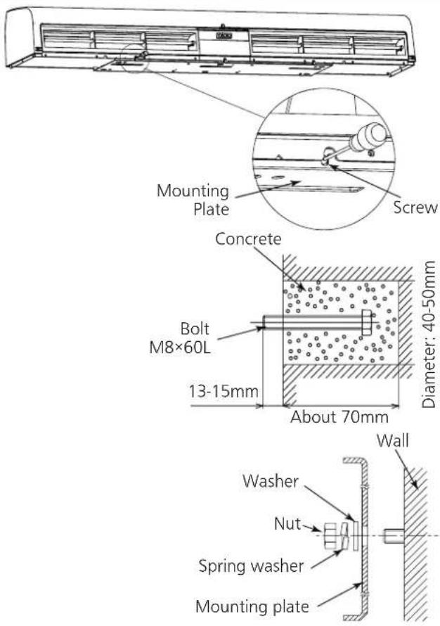
1. Fix the mounting plate
■Mounting on concrete wall.
-
Remove mounting plate from product. Taking the mounting plate by removing the 3 screws.
-
Firmly fix the bolts in the proper position.
-
Determine the position on the wall and drill into the wall.
• Fit the bolts into the holes. - Fill the holes with concrete.
- Install the mounting plate and check if it's secured when the concrete solidifies.
Notice
Distance of bolt head away from wall should be 13\~15mm.
- Fix the mounting plate with washers, spring washers and nuts.

CAUTION
■Please use the mounting plate provided with product to avoid the dropping caused by insufficient strength.
■Other installation methods
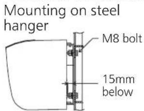
Mounting on wooden frame

Mounting inside the ceiling

Notice
- It's prohibited to install the product on hollow wall, otherwise it may produce noises.
-
Conduct the necessary reinforcement, depending on the particular condition to avoid noise resonance and vibration.
-
The inside space of ceiling should exceeding the dimensions as indicated above to ensure the space of air inlet, please select the larger model if space of air inlet can't be reserved.
- Don't place the substances near the air inlet or outlet grille (include the grille). It could affect the performance.
2. Preparation before wiring (Carry out this step if the distance between top face of product and ceiling is less than 150mm.)
Pre-hang up the product into the bottom holes of mounting plate.

How to install
3. Wiring

WARNING
■Wiring is required to follow the local wiring regulations. Otherwise, it may cause fire.
■ Please select 60227 IEC 53 ordinary polyvinyl chloride sheathed cord. Nominal cross-sectional area of conductors is 3 × 1.0 mm^2 . Otherwise, it may cause fire.
■The product is not provided with Double pole switch and leakage protection switch. Please purchase them in market.
- It is required to use terminal (not supply) that complies IEC 60998 and wiring box (not supply) that complies local regulation.
- Wiring should be firmly connected without any loose.
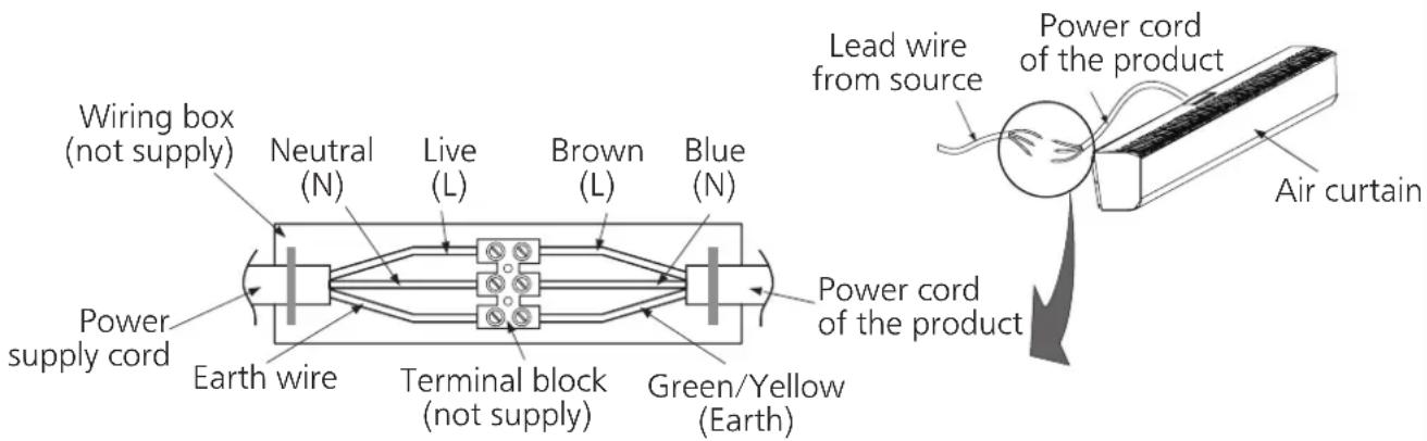
■ Connect the power cord (included earth) of product to lead wire in accordance with the wiring diagram.
■ Make sure all connections are fastened firmly after finishing wiring.
4. Installation of product
- Remove the product from the bottom holes.
- Fixing the product.
Align the groove of back panel with both sides of mounting plate. Fit the hooks into the top holes of mounting plate.
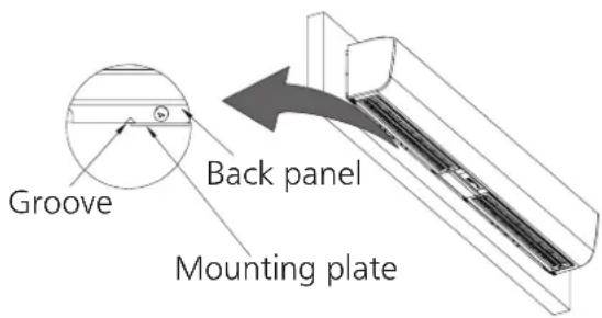
- Fasten the screws. (3 places)
Notice
The torque is suggested to be 1.2N·m.

Multiple products operate in group

WARNING
■Please select the switch of whose capacity has 1.2 \~ 1.5 times total current, when multiple products operate.
■Earth leakage breaker protector should be equipped, otherwise it may cause an electrical shock.
■The number of interlocking operation is not more than 6.
- Please purchase necessary parts following with local electrical requirements, except the power supply cord.
Power supply cord

natural_image
Pure electrical circuit lines without any symbolsWiring diagram

flowchart
graph TD
    A["Red"] --> B["Orange Capacitor"]
    B --> C["Black Black Switch"]
    C --> D["White(H) White"]
    C --> E["Yellow(L) Yellow"]
    D --> F["N L"]
    E --> F
    F --> G["Blue Brown"]
    G --> H["N L"]
    H --> I["Power Source"]
    J["Terminal"] --> K["Green/Yellow"]
    K --> L["Contact Point Separate Distance Over 3mm"]
Operation methods
Operation of Control panel
Panasonic
FY-4009U1

※Representative model
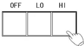
1 Start to operate

Press "HI" or "LO" button to start the product as shown in left figure.
2 Select the mode of operation
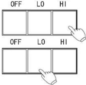
Press "HI" button if high air velocity is required.
Press "LO" button if quiet and low velocity is required.
Operation methods
3 Stop operating
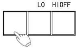
Press "OFF" button to stop the product.
Notice
The product is in stand-by mode after pressing the "OFF", it's still connected to the power.
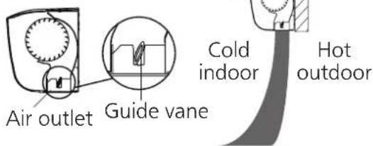
■ Guide vane in air outlet can be adjusted according to service environment to reach the ideal separation performance.
1 While strong wind in outdoor


2 While light wind in outdoor

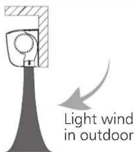
3 Heating
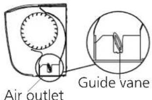

4 Cooling
- Room has opening (window, grille, etc.)
- Room is air tight (no opening)


Routine maintenance

WARNING
■Make sure to disconnect power supply before cleaning product.

Otherwise, the product might operate with the possibility of electric shock or injury.
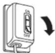
■Please contact entrusted distributor where you purchased or qualified persons to service the product.

Otherwise, it may damage the product or cause fire.
- It's prohibited to insert fingers or sticks into the product, air inlet or outlet.

Impeller at high speed rotation may cause injuries.
■Do not let water flow into the motor.


Otherwise, it may damage the product or cause fire.
■If you will not use this product any more, remove the product.

Otherwise, the product may fall down and it may cause injury.
■Once flammable gas leaks, do not start any function of this product.

Otherwise, it may generate sparkle and this leads to explosion.
- Don't turn on or off the power with wet hands.

It may cause a electrical shock.
■Immediately stop to wait for repair if abnormalities happen (noise, vibration, smell).

It may cause the unexpected accidents.
- It's prohibited to place the burning appliances in a position where product directly blows.


It may result in carbon monoxide poisoning caused by incomplete combustion.

CAUTION
■2 persons are required to conduct the maintenance.

Otherwise, the product may fall down and it may cause injury.
■It's forbidden to hang anything on the product.

Product may drop due to the increased weight.
■Please wear the gloves when cleaning the product.


Otherwise, it may cause damage.
■Do not directly spray this product with water and other liquids.

Otherwise, it may cause short circuit or electric shock.
Routine maintenance

CAUTION
■Eyes should not be faced to the air outlet (specially when the product stars up).

The blowing substance could damage your eyes.
■Please don't place the substances near to the air outlet or inlet grille.

It may result in personal injuries due to blowing out or sucking in.
■The strong air from air curtain may cause the sand and dust.

It may result in personal injuries.
■Never use petrol, benzene, thinner of any other such chemicals for cleaning the product.


Otherwise, dropping caused by corrosion of product, which may result in personal injuries.
Notice
■Make sure to disconnect power supply before cleaning product.
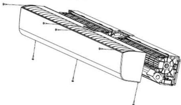
■Disassembly of part This part can be easily taken out by removal of 7 screws as indicated in the right figure.

natural_image
Technical line drawing of an air conditioner unit with internal cooling fins and mounting holes (no text or labels)Trouble shooting
Check according to the following table and take measures. If the product still does not work normally, disconnect the power and contact After-Sale Service Center or the dealer.
| Condition 1st Possible | reason 2nd Possible reason | 3rd Possible reason | ||
| Primary Period | Can’t operate. Check the voltage. Wiring is not correct.(P7) | |||
| With large noise or significant vibration. | Installed not properly.(P6~P7) | |||
| Poor separation performance. | Not suitable model. Guide vane is not in proper position.(P9) | Product is installed vertically. | ||
| During operation | Can’t operate. Wiring is not fixed. Double pole switch became off. | |||
| Poor separation performance. | Air inlet grille is blocked. | |||
| With large noise or significant vibration. | Dust piles up in impeller. | Any other substances fell into the product. | Motor runs abnormally. | |
Specifications
Voltage: 1 phase 220V Frequency: 50Hz
| Model | Outlet Velocity m/s | Power Consumption W | Current A | Noise dB(A) | Air Volume m^3/h | Insulation Class | Length mm | Weight kg | Installation height (m) | |||||
| High | Low | High | Low | High | Low | High | Low | High | Low | |||||
| FY-3509U1 | 11 | 9 | 95 | 85 | 0.41 | 0.39 | 51 | 49 | 1150 | 1000 | B | 900 | 12 | 3.5 |
| FY-3512U1 | 10.5 | 8.5 | 114 | 100 | 0.49 | 0.46 | 49 | 46 | 1550 | 1300 | B | 1200 | 14.5 | 3.5 |
| FY-4009U1 | 12 | 10 | 110 | 94 | 0.5 | 0.43 | 54.5 | 51 | 1340 | 1190 | B | 900 | 12.5 | 4.0 |
| FY-4012U1 | 12 | 10 | 126 | 105 | 0.59 | 0.49 | 52.5 | 48.5 | 1700 | 1530 | B | 1200 | 15.5 | 4.0 |
Voltage: 1 phase 240V Frequency: 50Hz
| Model | Outlet Velocity m/s | Power Consumption W | Current A | Noise dB(A) | Air Volume m^3/h | Insulation Class | Length mm | Weight kg | Installation height (m) | |||||
| High | Low | High | Low | High | Low | High | Low | High | Low | |||||
| FY-3509U1 | 11.5 | 9.5 | 99 | 96 | 0.42 | 0.4 | 54 | 51 | 1200 | 1050 | B | 900 | 12 | 3.5 |
| FY-3512U1 | 11 | 9 | 122 | 112 | 0.51 | 0.47 | 51 | 48 | 1650 | 1400 | B | 1200 | 14.5 | 3.5 |
| FY-4009U1 | 12.5 | 10.5 | 122 | 100 | 0.51 | 0.43 | 56.5 | 53.5 | 1360 | 1200 | B | 900 | 12.5 | 4.0 |
| FY-4012U1 | 12.5 | 10.5 | 139 | 110 | 0.6 | 0.49 | 54.5 | 51 | 1800 | 1580 | B | 1200 | 15.5 | 4.0 |
Notice
- The parameters as shown in above table are measured at ambient temperature of 20°C.
- The noise value is measured 1.5m away from the product at angle of 45° below the air outlet.
- Because the above-mentioned velocity is measured in test laboratory where it's empty, without air flow and obstacle, after actual installation the velocity may vary depending on different service environment.
- Outlet velocity is the maximum value.
Hướng dẫn an toàn

Nhìn từ bên phải

natural_image
Simple line drawing of a wall-mounted device with three legs and a top handle (no text or symbols)
natural_image
Pure electrical circuit lines without any symbolsSơ đồ đi dây

※ Hình minh họa
1 Bắt đầu vận hành
natural_image
Technical line drawing of an air duct system with internal components and mounting holes (no text or labels)Khắc phục sự cố


- Panasonic®
- INSTALLATION AND OPERATING INSTRUCTIONS
- HUỐNG DÂN LẮP ĐẶT
- VÀ SỬ DỤNG
- Air Curtain
- QUAT CHĂN GIÓ
- Model No. Model
- Contents
- Nội dung
- Please observe strictly
- WARNING
- CAUTION
- Installation cautions
- Supplied accessories
- Parts name and dimensions
- Notice
- Requirement of installation
- How to install
- Fix the mounting plate
- Preparation before wiring (Carry out this step if the distance between top face of product and ceiling is less than 150mm.)
- Wiring
- Installation of product
- Multiple products operate in group
- Wiring diagram
- Operation methods
- Stop operating
- Routine maintenance
- Trouble shooting
- Specifications
- Hướng dẫn an toàn
- Sơ đồ đi dây
- Khắc phục sự cố
Brand : PANASONIC
Model : FY-AC-STD-SPP
Category : Household Fan