
FV-0510VSL1 - Household Fan PANASONIC - Free user manual and instructions
Find the device manual for free FV-0510VSL1 PANASONIC in PDF.


| Product Type | Ventilating Fan (Exhaust) |
| Model Number | FV-0510VSL1 |
| Brand | Panasonic |
| Power Supply | AC 120 V, 60 Hz |
| Duct Diameter | 4 inches |
| Air Volume (CFM) | 50, 80, 100 (adjustable via Pick-A-Flow switch) |
| Noise Level (sones) | <0.3 at 50 CFM, 0.4 at 80 CFM, 0.9 at 100 CFM |
| Motor Speed (RPM) | 733 at 50 CFM, 856 at 80 CFM, 954 at 100 CFM |
| Power Consumption (W) | 4.5 (50 CFM), 8.5 (80 CFM), 12.4 (100 CFM) |
| Weight | 7.9 lb (3.6 kg) |
| Motor Type | DC motor |
| Technology | SmartFlow microchip (automatic static pressure compensation) |
| Control Switch | Pick-A-Flow switch (3-speed manual) |
| Lighting | Integrated LED lamp, 10 W (equivalent to 40 W incandescent) |
| Safety Certifications | UL listed for tub/shower enclosures, FCC Part 15B compliant |
| Installation Type | Ceiling joist or wall stud mounting |
| Duct Connection | 4-inch circular duct (3-inch with reducer accessory) |
| Warranty | Limited warranty (details in manual) |
| Maintenance Interval | Annual cleaning of grille and fan body |
| Special Notes | Requires GFCI if installed over tub/shower; not for use with solid-state speed controls |
Frequently Asked Questions - FV-0510VSL1 PANASONIC
User questions about FV-0510VSL1 PANASONIC
0 question about this device. Answer the ones you know or ask your own.
Ask a new question about this device
Download the instructions for your Household Fan in PDF format for free! Find your manual FV-0510VSL1 - PANASONIC and take your electronic device back in hand. On this page are published all the documents necessary for the use of your device. FV-0510VSL1 by PANASONIC.
USER MANUAL FV-0510VSL1 PANASONIC
Installation and Operating Instructions
Ventilating Fan
Model No. FV-0510VSL1
FV-0510VSCL1
FV-0810VSSL1
CONTENTS

natural_image
Technical line drawing of a mechanical ventilation or HVAC unit with a central fan and mounting bracket (no text or symbols)GENERAL SAFETY INFORMATION---- 2\~4
DESCRIPTION 4
UNPACKING 4
SUPPLIED ACCESSORIES----5
DIMENSIONS----5
WIRING DIAGRAM----5
FEATURE----6
PLEASE READ PRIOR BEFEOR INSTALLATION----7
INSTALLATION I (JOIST MOUNTING)---- 7\~9
INSTALLATION II (WALL MOUNTING)----10
MAINTENANCE (CLEANING)----10\~11
TROUBLE SHOOTING GUIDE 11
PRACTICAL GUIDE TO INSTALLATION --- BACK COVER
SPECIFICATIONS BACK COVER
PRODUCT SERVICE BACK COVER
READ AND SAVE THESE INSTRUCTIONS
Thank you for purchasing this Panasonic product.
Please read these instructions carefully before attempting to install, operate or service the Panasonic product. Please carefully read the "GENERAL SAFETY INFORMATION" (P.2\~4) of this manual before use. Failure to comply with instructions could result in personal injury or property damage. Please explain to users how to operate and maintain the product after installation, and this booklet should be presented to users. Please retain this booklet for future reference.
GENERAL SAFETY INFORMATION
For Your Safety
To reduce the risk of injury, loss of life, electric shock, fire, malfunction, and damage to equipment or property, always observe the following safety precautions.
Explanation of symbol word panels
The following symbol word panels are used to classify and describe the level of hazard, injury, and property damage caused when the denotation is disregarded and improper use is performed.

WARNING
Denotes a potential hazard that could result in serious injury or death.

CAUTION
Denotes a hazard that could result in minor injury.
NOTICE
Denotes a hazard that could result in property damage.
The following symbols are used to classify and describe the type of instructions to be observed.

This symbol is used to alert users to a specific operating procedure that must be followed in order to operate the unit safely.

This symbol is used to alert users to a specific operating procedure that must not be performed.

This symbol is used to alert users not to disassemble the equipment.

This symbol is used to alert users to make sure of grounding when using the equipment with the grounding terminal.

WARNING
To reduce the risk of fire, electric shock or injury to persons, observe the following :

Use this unit only in the manner intended by the manufacturer. If you have any questions, contact the manufacturer.

Before servicing or cleaning unit, switch power off at service panel and lock the service disconnecting means to prevent power from being switched on accidentally. When the service disconnecting means cannot be locked, securely fasten a prominent warning device, such as a tag, to the service panel.

Installation work and electrical wiring must be done by qualified person(s) in accordance with all applicable codes and standards, including fire-rated construction.

Sufficient air is needed for proper combustion and exhausting of gases through the flue (chimney) of fuel burning equipment to prevent back drafting. Follow the heating equipment manufacturer's guideline and safety standards such as those published by the National Fire Protection Association (NFPA), and the American Society for Heating, Refrigeration and Air Conditioning Engineers (ASHRAE) and the local code authorities.

When cutting or drilling into wall or ceiling, do not damage metal objects, electrical wiring and other hidden utilities.

Ducted fans must always be vented to the outdoors.
GENERAL SAFETY INFORMATION

WARNING

These models are UL listed for tub and shower enclosures.

A statement to the effect that when the product is to no longer be used, it must not be left in place but remove, to prevent it from possibly falling.

Ceiling joist or wall stud must be subjected to static load more than five times the weight of the product.

Install the fan at least 1.5 m (5 feet) above the floor, and the fan must be installed above a counter or major appliances that serves as a barrier.

If this unit is to be installed over a tub or shower, it must be marked as appropriate for the application and be connected to a GFCI (Ground Fault Circuit Interrupter) - protected branch circuit.

The product must be properly grounded.

Do not install with a method which is not approved in the instructions.

Do not use this fan with any solid-state speed control device. Solid state controls may cause harmonic distortion which can cause motor humming noise.

Canada only: Not to be installed in a ceiling thermally insulated to a value greater than R40.

Do not disassemble the unit for reconstruction. It may cause fire or electric shock.

CAUTION

Follow all local electrical and safety codes, as well as the National Electrical Code (NEC) and the Occupation Safety and Health Act (OSHA).

Make sure that the electric service supply voltage is AC 120 V, 60 Hz.

Always disconnect the power source before working on or near the fan, motor, light fixture or junction box.

Protect the supply wiring from sharp edges, oil, grease, hot surfaces, chemicals or other objects.

The special-purpose or dedicated parts, such as mounting fixtures, must be used if such parts are provided.

Please wear gloves to protect hands during installation.

Do not install this ventilating fan where interior room temperature may exceed 104 °F (40 °C).

For general ventilating use only. Do not use to exhaust hazardous or explosive materials and vapors.

Do not kink the supply wiring.

Not for use in cooking area. (Fig.A)
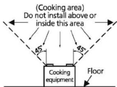
Fig. A
GENERAL SAFETY INFORMATION
NOTICE

Provide make up air for proper ventilation.

When one switch is connected with two or more products in parallel, the unit may not function. Therefore, parallel connection must not be allowed.

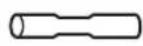
Do not install the product where ducts are configured as shown in below.

Excessive bending

Successive bending
Squeezed duct
Adaptor

Bend close to duct adaptor
DESCRIPTION
These products are listed by UL under UL file No. E78414.
These products use a sirocco fan driven by a DC motor powered by an integral transformer. The motor is designed to have long operating life, high dynamic response, higher speed ranges with saving energy. The grille covering the fan body is a spring-loaded, quick remove type. A damper for preventing air counter flow is provided. The blower uses a high-capacity sirocco fan developed to reduce the noise level.
The lighting unit is an energy-saving LED lighting device that uses one 10 W LED lamps and produces almost the same illumination as a standard 40 W incandescent lamp.
FCC Note: This equipment has been tested and found to comply with the limits for a Class B digital device, pursuant to Part 15B of the FCC Rules. These limits are designed to provide reasonable protection against harmful interference in a residential installation. This equipment generates, uses and can radiate radio frequency energy and, if not installed and used in accordance with the instructions, may cause harmful interference to radio communications. However, there is no guarantee that interference will not occur in a particular installation. If this equipment does cause harmful interference to radio or television reception, which can be determined by turning this product on and off, the user is encouraged to try to correct the interference by one of the following measures:
• Reorient or relocate the receiving antenna.
- Increase the separation between the equipment and receiver.
- Connect equipment into outlet on a circuit different from that to which the receiver is connected.
- Consult the dealer or an experienced radio/TV technician for help.
Warning: This equipment must be installed by qualified person in accordance with the provided installation instructions; and all applicable codes and standards. Also, any changes or modifications not expressly approved by the party responsible for compliance could void the user's authority to operate this equipment.
DoC Responsible Party: Panasonic Corporation of North America
Two Riverfront Plaza, Newark, NJ 07102
Customer Call Support: 1-866-292-7299
This device complies with Part 15B of the FCC Rules. Operation is subject to the following two conditions:
(1) This device may not cause harmful interference, and (2) this device must accept any interference received, including interference that may cause undesired operation.
Risk of Fire: Type IC-Inherently Protected.
UNPACKING
Unpack and carefully remove the product from carton.
Refer to the supplied accessories list to verify that all parts are present.
SUPPLIED ACCESSORIES
| Part name | Appearance | Quantity |
| Grille |  | 1 |
| Long screw(ST4.2X30) |  | 5(1 for spare) |
| Part name | Appearance | Quantity |
| Installation and operating instructions |  | 2 |
| Limited warranty |  | 1 |
DIMENSIONS


Unit: inches (mm)
| No. | Part name |
| 1 | PCB box |
| 2 | Blower assy |
| 3 | Blade |
| 4 | Pick-A-Flow switch |
| 5 | Multi-Speed switch(FV-0810VSSL1 only) |
| Induction humidity setting switch(FV-0510VSCL1 only) | |
| 6 | Condensation sensor(FV-0510VSCL1 only) |
| 7 | LED lamp |
| 8 | Grille |
| 9 | Adaptor |
| 10 | Junction box |
| 11 | Connector plate |
| 12 | Damper |
| 13 | Suspension bracket |
| 14 | Fan body |
WIRING DIAGRAM
| Fan body | Junction box | ||
| DC motor | Main control circuit | Black | Power switchLive (Fan)Power supply AC 120 V 60 Hz |
| White | Neutral | ||
| Condensation sensor(FV-0510VSCL1 only,other models not included) | Red | Control switch (No need for FV-0510VSL1)There is no red wire in FV-0510VSL1. | |
| Red | Green | ||
| Green | |||
| LED lamp | Junction box | ||
| Black | Power switchLive (N. Light)Power supply AC 120 V 60 Hz | ||
| White | Neutral | Power supply AC 120 V 60 Hz | |
| Black | Live (Light) | Power supply AC 120 V 60 Hz | |
FEATURE
These products employ innovative, state-of-the-art technologies that provide a number of customizable unique features that lead to improved indoor air quality. Please read this manual first in order to realize the benefits of this customizable, modular fan.
Optimum ventilation performance:
Duct length, elbows and other factors increase static pressure which can hinder the performance of most ventilation fans. These products utilize SmartFlow microchip technology that monitors the static pressure in the system and speeds up or slows down the rpm of the fan depending upon the amount of resistance within the ducts. This feature allows the fan to perform as rated and avoid potential installation issues.
Outstanding energy savings:
These products are built using DC motor technology. The DC motor is 30%\~70% more energy efficient than the minimum ENERGY STAR requirements.
[For model : FV-0510VSL1]
This product can set air volume by Pick-A-Flow switch, and operate as below.
![PANASONIC FV-0510VSL1 - [For model : FV-0510VSL1] - 1](/content/2026/05/1062032/images/dd57a4fac44300c1af4326434c8bea7afbe6da3aaa1c98efd6e5de65db479c57.jpg)
flowchart
graph LR
    A["Power switch"] --> B["ON"]
    B --> C["OFF"]
    D["Product"] --> E["Run"]
    E --> F["Stop"]
Pick-A-Flow switch

[For model : FV-0810VSSL1]
This product can set the high air volume by Pick-A-Flow switch, and set the low air volume by Multi-speed switch, and operate as below.
![PANASONIC FV-0510VSL1 - [For model : FV-0810VSSL1] - 1](/content/2026/05/1062032/images/1e6f09a8212f47ba9f2fdd079885dab2cc69e150bc92077002dc29247a7f9e38.jpg)
flowchart
graph LR
    A["Power switch"] --> B["ON"]
    B --> C["OFF"]
    D["Control switch"] --> E["OFF"]
    E --> F["ON"]
    G["Product"] --> H["Run in low air volume*1"]
    H --> I["Run in high air volume"]
    I --> J["Stop"]
*1 When the low air volume is set 0 CFM, the product will stop running.

[For model : FV-0510VSCL1]
This product can set air volume by Pick-A-Flow switch, and set humidity by Induction humidity setting switch, and operate as below.
![PANASONIC FV-0510VSL1 - [For model : FV-0510VSCL1] - 1](/content/2026/05/1062032/images/465b0e26ec79ebd362551ec2500e2c36bcf0df5fc4f643a12755185ca5a05b65.jpg)
flowchart
graph LR
    A["Power switch"] --> B["ON"]
    B --> C["OFF"]
    D["Control switch"] --> E["OFF"]
    E --> F["ON"]
    G["Condensation sensor"] --> H["Environment humidity"]
    H --> I["Humidity setting about 5 %RH"]
    I --> J["Product"]
    J --> K["Stop"]
    K --> L["Run"]
    L --> M["Delay operation*2"]
    M --> N["Stop"]
    N --> O["Run"]
    O --> P["Stop"]

Induction humidity setting switch
*2 The product will continue run about 20 minutes when detects the environment humidity is about 5 %RH lower than the humidity setting, then stop running.
Note:
- The product will also run when environment humidity rise rapidly but not reach to the humidity setting, and stop after delay operation.
- Induction humidity setting switch is stepless change between 30 %RH\~80 %RH.
3.The humidity detected by sensor may differ from the value on your hygrometer. - The product may on and off cause by the unstable environment humidity, you can improve it by adjusting the Induction humidity setting switch.
PLEASE READ PRIOR BEFORE INSTALLATION
[For model : FV-0810VSSL1]
Spot and continuous ventilation:
This product is designed to run continuously ensuring a healthy environment at low airflow levels 24 hours a day. By utilizing the CustomVent Multi-speed module the product is built to run continuously at a pre-set lower level (0, 30, 40, 50, 60, 70 CFM). The setting is dependent on the size of the house and the individual wishes of the homeowner. It is crucial that the installer pre-set the lower setting during the installation. Please refer to the chart below and the switch indication on page 6.
CustomVent Multi-speed module (Lower setting). ASHRAE 62.2-2010
| (sq.feet) | Two Bedrooms | Three Bedrooms | Four Bedrooms | Five Bedrooms |
| <1,000 | 33 | 40 | 48 | 55 |
| 1,500 | 38 | 45 | 53 | 60 |
| 2,000 | 43 | 50 | 58 | 65 |
| 2,500 | 48 | 55 | 63 | 70 |
| 3,000 | 53 | 60 | 68 | 75 |
| 3,500 | 58 | 65 | 73 | 80 |
| 4,000 | 63 | 70 | 78 | 85 |
| 4,500 | 68 | 75 | 83 | 90 |
| 5,000 | 73 | 80 | 88 | 95 |
| 5,500 | 78 | 85 | 93 | 100 |
| 6,000 | 83 | 90 | 98 | 105 |
| 6,500 | 88 | 95 | 103 | 110 |
| 7,000 | 93 | 100 | 108 | - |
This product is also built to take care of the homeowner's spot ventilation needs when the room is occupied and kicks up to a maximum level of 100 CFM when control switch is turned on.
INSTALLATION I (JOIST MOUNTING)
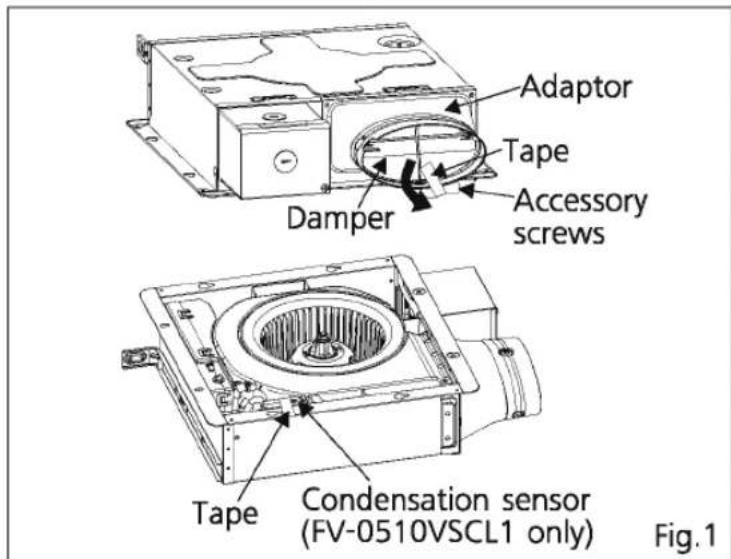
- Before installation, please remove the tape which protects damper during shipping and accessory screws from adaptor and the tape which fixes condensation sensor (FV-0510VSCL1 only), then check that the damper can open and close smoothly. (Fig.1)
Note:
Please remove the tape on damper according to the direction of arrow in Fig.1, otherwise the damper may be pulled out.
- Open one knock-out hole on junction box. (Fig.2)
Note:
There are two knock-out holes, please open one which is convenient for wiring.

INSTALLATION I (JOIST MOUNTING)
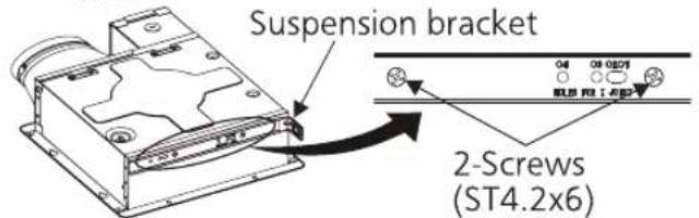
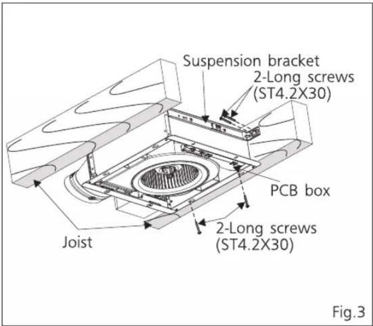
- Fix the flange of frame to joist by 2 long screws (ST4.2X30), and fix the suspension bracket to joist by 2 long screws (ST4.2X30). (Fig.3)

CAUTION

The screws for fixing suspension bracket should not be replaced by other screws, otherwise the cord in PCB box may be damaged and cause fire.
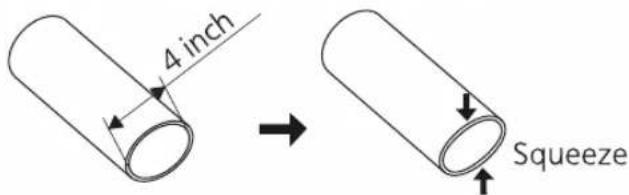
4.A 4 inch circular duct is needed to connect to the relevant part of adaptor.
Squeeze a circular exhaust duct to fit the adaptor, then slip it onto adaptor and secure it with clamps, or ties and seal it with mastic or approved foil tape. (Fig.4)
Note:
If using 3 inch round duct, please purchase the 26 gauge steel Panasonic 4" Oval - 3" Round reducer from our representative.
-
Remove junction box cover and secure conduit or stress relief to the opened knock-out hole. (Fig.4)
-
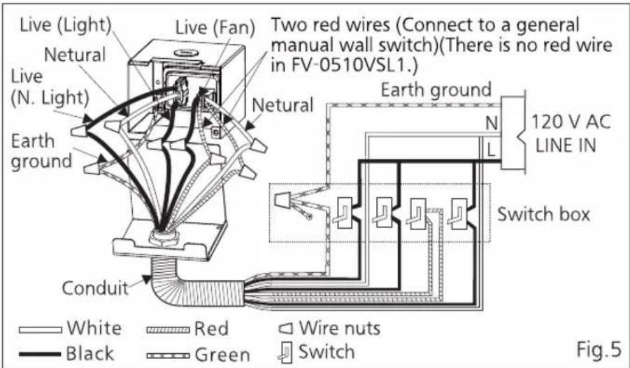
Refer to wiring diagram (P.5), follow all the local electrical safety codes as well as the National Electrical Code (NEC). Using UL approved wire nuts, connect house power wires to ventilating fan wires. (Fig.5)

CAUTION

Mount junction box cover carefully so that lead wires are not pinched.

INSTALLATION I (JOIST MOUNTING)
- Finish ceiling work. Ceiling hole should be aligned with the inside edge of the flange. (Fig.6)
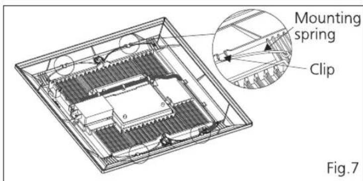
- Take out the mounting springs from clips. (Fig.7)
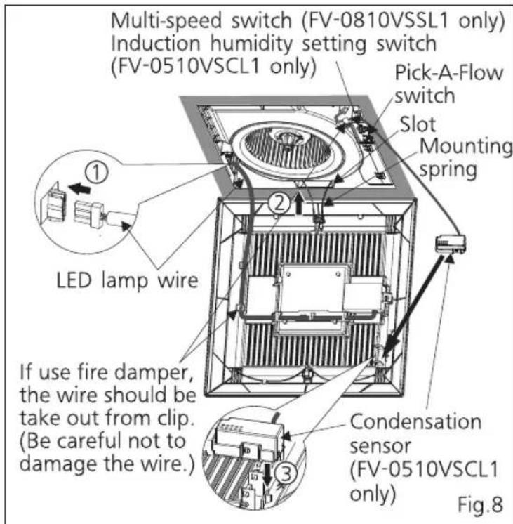
- Connect the LED lamp wire to fan body as show in Fig.8 ①.
- Insert one mounting spring into slot as show in Fig.8 ②. (If not, the grille may not be installed.)
- Fix the condensation sensor (FV-0510VSCL1 only) into grille as shown in Fig.8 ③.
Note:
Make sure the condensation sensor is fixed completely.
- Adjust Pick-A-Flow switch, Multi-speed switch (FV-0810VSSL1 only), Induction humidity setting switch (FV-0510VSCL1 only) as you want. (Refer to indication on P.6)
- Insert the other mounting spring into slot as shown and mount grille to fan body. (Fig.9)


INSTALLATION II (WALL MOUNTING)
- Before installation, please refer to step 1 to 2 of INSTALLATION I. (P.7)
- Fix the flange of frame to stud by 2 long screws (ST4.2X30), and fix the suspension bracket to stud by 2 long screws (ST4.2X30). (Fig.10)

CAUTION
The adaptor of product must be installed upward. (Fig.10)
The screws for fixing suspension bracket should not be replaced by other screws, otherwise the cord in PCB box may be damaged and cause fire.

- Complete the wiring and duct work, please refer to step 4 to 6 of INSTALLATION I. (P.8)
- Finish the wall work. Wall hole should be aligned with the inside edge of the flange. (Fig.11)
- Install the grille, please refer to step 8 to 13 of INSTALLATION I. (P.9)


After finishing the wall job, fill gap between flange and wall with caulk or other sealant to prevent air leakage. Fig.11
! Disconnect power source before working on unit.

CAUTION
! Routine maintenance must be done every year. Please wear gloves during the cleaning work.
Do not immerse motor, LED lamp, condensation sensor in water when cleaning.
NOTICE
Do not soak resin parts in water over 140 °F (60 °C).
Never use gasoline, benzene, thinner or any other such chemicals for cleaning the product.
- Clean grille. (Don't put into water. Use non-abrasive kitchen detergent. Wipe dry with clean cloth.) (Fig.12)
- Remove one mounting spring from the grille on the condensation sensor side. (Fig. 13)


-
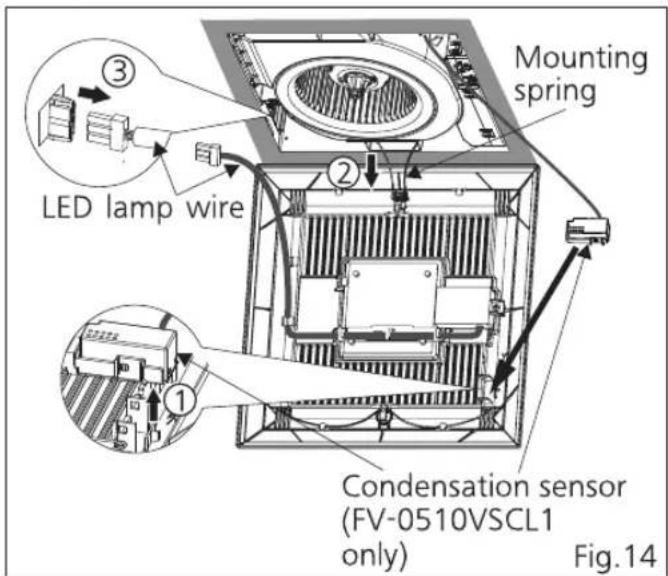
Remove condensation sensor (FV-0510VSCL1 only). (Fig.14 ①)
-
Remove the other mounting spring. (Fig.14 ②)
-
Take the LED lamp wire out to remove the grille. (Fig.14 ③)
-
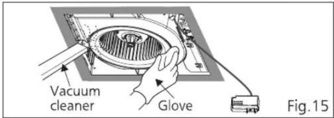
Remove dust and dirt from fan body using a vacuum cleaner. (Fig.15)
-
Using a cloth dampened with kitchen detergent remove any dirt from fan body. Wipe dry with clean cloth. (Fig.15)
-
Reinstall grille, please refer to Fig.8\~Fig.9 in P.9.
TROUBLE SHOOTING GUIDE
Check according to the following table and correct the problem. If the fan still does not work correctly, please disconnect the power source and contact the dealer.
| PROBLEM | CAUSE | ACTION |
| 1.The product can not stop.(FV-0510VSCL1 only) | Is the humidity setting nearly the environment humidity? | Please adjust the humidity setting higher than environment humidity. (P.6) |
| Are the two red wires wrong connect? If the two red wires are short connected, the fan will keep running at Pick-A-Flow. | Disconnect the power source, remove the connector plate to check the wire connection. (If the connector plate (P.5) can not be removed, please remove the blower assy first, then the connector plate can be removed.) | |
| 2.The product can not operate. | Are the lead wires connection get loosen that result in open circuit? | |
| Is the Multi-speed switch setting 0 CFM?(FV-0810VSSL1 only) | If the product controls by Multi-speed switch, it will not operate at 0 CFM setting. (P.6) | |
| 3.There is an unusual sound. | Is the shutter opening normally? | Please check the shutter can open normally before the installation. (P.7) |
| Is the grille mounted rightly on the ceiling? | Please check the grille and ceiling surface, make sure that no foreign matter on the mounting surface. | |
| Is the installed screw get loose? | Please check all installed screws in the product, tight the loosen one. | |
| If the above measures do not solve the problem. | Please disconnect the power source and contact the dealer for service. | |
| 4.The humidity is lower than the setting, why the product also runs?(FV-0510VSCL1 only) | CAUSE | |
| The product will continue run about 20 minutes when detects the environment humidity is about 5 %RH lower than the humidity setting, then stop running. | ||
| The humidity detected by sensor may differ from the value on your hygrometer. | ||
PRACTICAL GUIDE TO INSTALLATION
Properly insulate the area around the fan to minimize building heat loss and gain. (Fig.16) Loose fill or batt insulation can be placed directly over the fan housing in the attic. Our fans and fan/light combination units do not create excessive heat that is a common problem with recessed light fixtures or some competitor's fan/light combination. Our efficient, cool-running motors and our LED lighting unit do not create enough ambient heat to be subjected to these limitations. The ducting from this fan to the outside of the building has a strong effect on the air flow, noise and energy use of the fan. Use the shortest, straightest duct routing possible for best performance, and avoid installing the fan with smaller ducts than recommended. Insulation around the ducts can reduce energy loss and inhibit mold growth. Fans installed with existing ducts may not achieve their rated air flow.

SPECIFICATIONS
| Model No. | Air direction | Voltage (V) | Frequency (Hz) | Duct diameter (inches) | Air volume at 0.1" WG (CFM) | Noise (sones) | Speed (rpm) | Power (W) | Weight lb.(kg) |
| FV-0510VSL1 | Exhaust | 120 | 60 | 4 | 50 | <0.3 | 733 | 4.5 | 7.9(3.6) |
| 80 | 0.4 | 856 | 8.5 | ||||||
| FV-0510VSCL1 | 100 | 0.9 | 954 | 12.4 | |||||
| FV-0810VSSL1 | Exhaust | 120 | 60 | 4 | 30 | <0.3 | 711 | 3.4 | |
| 40 | <0.3 | 723 | 3.8 | ||||||
| 50 | <0.3 | 733 | 4.5 | ||||||
| 60 | <0.3 | 770 | 5.3 | ||||||
| 70 | <0.3 | 805 | 6.5 | ||||||
| 80 | 0.4 | 856 | 8.5 | ||||||
| 100 | 0.9 | 954 | 12.4 |
HVI Certified performance based on HVI Procedures 915, 916, and 920.
PRODUCT SERVICE
Warning Concerning Removal of Covers. The unit should be serviced by qualified technicians only. Your product is designed and manufactured to ensure a minimum of maintenance. Should your unit require service or parts, call Panasonic Call Center at 1-866-292-7299 (USA) or 1-800-669-5165 (Canada).
Panasonic Corporation of North America
Two Riverfront Plaza, Newark, NJ 07102
www.panasonic.com
© Panasonic Corporation 2017
Panasonic Canada Inc.
5770 Ambler Drive, Mississauga, Ontario L4W 2T3
www.panasonic.com
Printed in China
Issue date: 05/2017
P0517-0 510SCL420


- Installation and Operating Instructions
- Ventilating Fan
- CONTENTS
- READ AND SAVE THESE INSTRUCTIONS
- GENERAL SAFETY INFORMATION
- For Your Safety
- Explanation of symbol word panels
- WARNING
- CAUTION
- NOTICE
- DESCRIPTION
- UNPACKING
- FEATURE
- Optimum ventilation performance:
- Outstanding energy savings:
- [For model : FV-0510VSL1]
- [For model : FV-0810VSSL1]
- [For model : FV-0510VSCL1]
- Note:
- PLEASE READ PRIOR BEFORE INSTALLATION
- INSTALLATION I (JOIST MOUNTING)
- INSTALLATION II (WALL MOUNTING)
- TROUBLE SHOOTING GUIDE
- PRACTICAL GUIDE TO INSTALLATION
- PRODUCT SERVICE
- Panasonic Corporation of North America
- Panasonic Canada Inc.
Brand : PANASONIC
Model : FV-0510VSL1
Category : Household Fan