MLR10 - Measurement Megger - Free user manual and instructions
Find the device manual for free MLR10 Megger in PDF.

User questions about MLR10 Megger
0 question about this device. Answer the ones you know or ask your own.
Ask a new question about this device
Download the instructions for your Measurement in PDF format for free! Find your manual MLR10 - Megger and take your electronic device back in hand. On this page are published all the documents necessary for the use of your device. MLR10 by Megger.
USER MANUAL MLR10 Megger
Read this entire manual before operating.
Megger.
Valley Forge Corporate Center
2621 Van Buren Avenue
Norristown, PA 19403-2329
U.S.A.
610-676-8500
www.megger.com
MLR10
Leakage Reactance Tester
Copyright© 2009 by Megger. All rights reserved.
The information presented in this manual is believed to be adequate for the intended use of the product. If the product or its individual instruments are used for purposes other than those specified herein, confirmation of their validity and suitability must be obtained from Megger. Refer to the warranty information below. Specifications are subject to change without notice.
WARRANTY
Products supplied by Megger are warranted against defects in material and workmanship for a period of one year following shipment. Our liability is specifically limited to replacing or repairing, at our option, defective equipment. Equipment returned to the factory for repair must be shipped prepaid and insured. Contact your MEGGER representative for instructions and a return authorization (RA) number. Please indicate all pertinent information, including problem symptoms. Also specify the serial number and the catalog number of the unit. This warranty does not include batteries, lamps or other expendable items, where the original manufacturer's warranty shall apply. We make no other warranty. The warranty is void in the event of abuse (failure to follow recommended operating procedures) or failure by the customer to perform specific maintenance as indicated in this manual.
Megger.
Valley Forge Corporate Center 2621 Van Buren Ave Norristown, PA 19403-2329
610-676-8500 (Telephone) 610-676-8610 (Fax)
www.megger.com
Table of Contents
1 INTRODUCTION....1
Receiving Instructions....1
General Information....1
2 SAFETY 3
Precautions....3
3 SPECIFICATIONS....5
Minimum PC Recommended System 6
Software Installation Instructions and Cal Factor loading: 6
4 LEAKAGE REACTANCE TESTING 9
Single Phase Transformer....9
3 Phase Transformer - Per Phase - Y Primary 9
3 Phase Transformer - Per Phase - Delta Primary 10
3 Phase Transformer - 3 Phase Equivalent .... 10
Leadset Connections....11
Leakage Reactance Test Procedure 20
Capacitor Bank Test Procedure 22
5 Repair 25
List of Figures
Figure 1. Main AC Breaker 2
Figure 2. Output Over Current Breaker 2
Figure 3. Leakage Reactance Test screen....21
Figure 4. Capacitor Bank Test Connection 22
Figure 5. Capacitance Test Screen 24
Megger.
1
INTRODUCTION
Receiving Instructions
Check the equipment received against the packing list to ensure that all materials are present. Notify Megger of any shortage.
Examine the instrument for damage received in transit. If damage is discovered, file a claim with the carrier at once and notify Megger, giving a detailed description of the damage.
This instrument has been thoroughly tested and inspected to meet rigid specifications before being shipped. It is ready for use when set up as indicated in this manual.
General Information
text_image
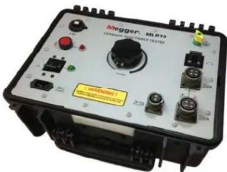
Megger. ML812 GRASSAGE PERFORMANCE TESTER WARNING!Leakage Reactance
The Megger Leakage Reactance Tester MLR10 is used to measure leakage reactance and other associated parameters in high voltage power transformers. Leakage reactance, or more generally leakage impedance, is measured at the transformer primary winding while the secondary winding is shorted. Ideally (and theoretically), a transformer's primary and secondary windings should be 100% coupled by magnetic flux, however, in real transformers there is always a small amount of leakage flux. Leakage inductance is a result of this leakage flux. The amount of leakage flux a transformer has is partially dependent on the configuration of the windings. Since leakage reactance depends on leakage flux, measuring a transformer's leakage reactance can give an indication of the condition of the windings. Changes in the leakage flux, and therefore the leakage
reactance, are generally caused by winding mechanical deformation. The mechanical deformation can occur during shipping, installation, or from a high current event while the transformer is in operation. Such changes can be detected by comparing before and after leakage reactance measurement values.
natural_image
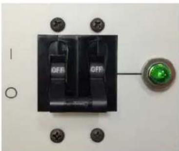
Close-up of a black electrical switch with two fuses and a green indicator light, mounted on a white surface with mounting holes (no text or symbols visible)Figure 1. Main AC Breaker
natural_image
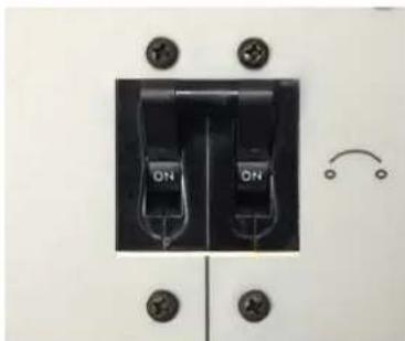
Close-up of a black electrical switch with two ON buttons and mounting holes (no text or symbols visible)Figure 2. Output Over Current Breaker
Capacitance Bank Testing
With the use of the MLR10's optional capacitance test probe, electrical measurements can be isolated to individual legs of a complex capacitive bank network. The MLR10 ac voltage source is applied across the appropriate capacitor section (containing the capacitance of interest) and the optional capacitance test probe is used to isolate the measurements specific to the capacitor of interest.

natural_image
Coiled black cable with red clamp and connector, no visible text or symbolsPC Control
Operation of the MLR10 is conducted while connected to an external companion laptop/PC. The MLR10 comes complete with the necessary software.
2
SAFETY
Precautions
The test set and the specimen to which it is connected are a possible source of high-voltage electrical energy and all persons making or assisting in tests must use all practical safety precautions to prevent contact with energized parts of the test equipment and related circuits. Persons actually engaged in the test must stand clear of all parts of the complete high-voltage circuit, including all connections, unless the test set is de-energized and all parts of the test circuit are grounded. Persons not directly involved with the work must be kept away from test activities by suitable barriers, barricades, or warnings.
Treat all terminals of high-voltage power equipment as a potential electric shock hazard. There is always the potential of voltages being induced at these terminals because of proximity to energized high-voltage lines or equipment. Always use a safety ground stick to ground the high-voltage conductor. A safety ground jumper must then be installed between all terminals of apparatus under test and ground. Always disconnect test leads from power equipment before attempting to disconnect them at the test set. The ground connection must be the first made and the last removed. Any interruption of the grounding connection can create an electric shock hazard.
This instrument operates from a single phase power source. It has a three-wire power cord and requires either a 120V line-neutral-ground or 240V line-line-ground connection, as below:
MLR10: 120V, 50/60Hz
MLR10-47: 240V, 50/60Hz
Before making connection to the power source, determine that the instrument rating matches the voltage of the power source and has a suitable two-pole, three-terminal grounding connector.
The power input plug must be inserted only into a mating receptacle with a ground contact. Do not bypass the grounding connection. Any interruption of the grounding connection can create an electric shock hazard. Determine that the receptacle is properly wired before inserting the plug.
It is not possible to eliminate all potential hazards from, and in using, electrical test equipment. For this reason, every effort has been made to point out in this instruction
manual the proper procedures and precautions to be followed by the user in operating this equipment and to mark the equipment itself with precautionary warnings where appropriate. It is not possible to foresee every hazard which may occur in the various applications of this equipment. It is therefore essential that the user, in addition to following the safety rules in this manual, also carefully consider all safety aspects of the test before proceeding.
■ Safety is the responsibility of the user.
- Misuse of this high-voltage equipment can be extremely dangerous.
- The purpose of this equipment is limited to use as described in this manual. Do not use the equipment or its accessories with any device other than specifically described.
■ Never connect the test set to energized equipment.
■ Operation is prohibited in rain or snow.
- Do not use the test set in an explosive atmosphere.
- A qualified operator should be in attendance at all times while the test equipment is in operation.
- Observe all safety warnings marked on the equipment.
- Corrective maintenance must only be performed by qualified personnel who are familiar with the construction and operation of the test set and the hazards involved.
- Refer to IEEE 510 - 1983, “IEEE Recommended Practices for Safety in High-Voltage and High-Power Testing,” for information.
If the test equipment is operated properly and all grounds correctly made, test personnel need not wear rubber gloves. As a routine safety procedure, however, some users require that rubber gloves be worn, not only when making connections to the high-voltage terminals, but also when manipulating the controls. Megger considers this an excellent safety practice.
High-voltage discharges and other sources of strong electric or magnetic fields may interfere with the proper functioning of heart pacemakers. Persons with heart pacemakers should obtain expert advice on the possible risks before operating this equipment or being close to the equipment during operation.
3
SPECIFICATIONS
AC Input 120 or 240 V at 10 A(50/60 Hz)
Inductance
Range: 250 H to 2 H (for <10% power factor at 50 or 60 Hz)
Accuracy: 1% of reading or ±10 H
Resistance Measurements
Range: 0.1 to 700 ohms (for >90% Power Factor)
Accuracy: 1% of reading or ±10 milliohms
Impedance Measurements: 0.1 to 700 ohms
0 to 280 VAC Output Voltage
2.6 kVA Output VA Continuous (at 240 V Input)
1.2 kVA Output VA Continuous (at 120 V Input)
Overload current: 25 A RMS 4 to 8 minutes
Operating Temperature: 32^ to 140^ F (0 to 60^ C)
Dimensions: 16 in. x 8 in. x 13 in.
(406 mm x 203 mm x 330 mm)
Weight: 31 lbs (14.1 kg)
Minimum PC Recommended System
- Operating System: Windows Server 2003; Windows Server 2008; Windows Vista; Windows XP
- Processor: 400 MHz Pentium Class processor minimum, 1 GHZ or better recommended
■ RAM: 96 MB RAM minimum, 512+ MB RAM recommended - Hard Disk: Up to 500 MB of available space may be required
■ Display: 800x600, 256 colors (minimum); 1024 x 768 high color, 32-bit (recommended)
Software Installation Instructions and Cal Factor loading:
Prior to a PC being able to control the MLR10, there are three software components that need to be installed on the PC. The first is Microsoft's .NET framework (which must be version 3.5 or higher). The second component needed are the hardware drivers. The third component is the MLR10 application software. Once these three software components are installed, then the MLR10's Calibration factors need to be loaded into the MLR10 software (now residing on the PC). In so doing, a given PC is then “linked” to the specific MLR10 for which the Calibration factors were installed. In the event the user desires for this same PC to be used to control another MLR10 instrument, then the Calibration factors for the other MLR10 would need to be loaded into this PC.
Note: The ML R10 software can only store the calibration factors for one ML R10 instrument at a lime.
Step 1: Microsoft .NET Framework
If the companion PC already contains version 3.5 (or higher) of Microsoft.NET framework, then skip to Step 2. To check the version, go to the Start menu and open the Control Panel. Then, open Add or Remove Programs and a list of all software installed on the PC will be displayed. Scroll down and look for Microsoft .NET Framework. If it is listed and is at version 3.5 (or higher), then go to Step 2. Otherwise, an install procedure must be conducted. To do this, navigate the CD provided and double-click the dotNET folder. Next, double-click the dotnetfx35.exe file. Follow the prompts to step through the .NET Framework installation procedure.
Step 2: Hardware Drivers
On the CD, open the Drivers folder. Then, open the NIDAQ871-1 folder. Next, double-click the setup.exe file to run it. Follow the prompts to step through the driver installation procedure.
Step 3: MLR10 Software
On the CD, open the MLR10 folder. Next, double-click the setup.exe file to run it. Follow the prompts to step through the MLR10 software installation procedure.
Step 4: Loading the Calibration Factors
On the Leakage Reactance screen, clicking the VI CALIBRATION button opens the Voltage Calibration Constant and Current Calibration Constant windows. Every MLR10 will get a sticker imprinted with two numeric calibration constants, one for voltage and one for current. The VI Calibration routine lets the user enter these values from their MLR10 into the software, thereby calibrating the software to that particular unit. Once selected, click Proceed and then:
Enter the voltage calibration constant stamped on the MLR10 and then click OK. The Current Calibration Constant window will then open. Enter the current calibration constant stamped on the MLR10 and then click OK. This completes the procedure.
Note: A SYSTEM INFO button can be seen on the lower-left portion of the software screen. This button is provided for diagnostic purposes only (in the event the MLR10 is sent in to an Authorized Service Center for evaluation).
Accessory Items
The following items are needed to perform Leakage Reactance and Capacitance testing with the Megger MLR10 Leakage Reactance Module.
■ MLR10 Leakage Reactance Module (with input Mains power cord)
■ Pair of MLR10 voltage leads (Kelvin pair, each containing source and sense lines)
■ MLR10 Grounding cable
- MLR10 USB cable
■ Shorting wire for LV winding (user supplied)
■ Companion laptop/PC (user supplied)
■ MLR10 Leakage Reactance Software module
■ Optional Capacitance Bank test kit
Megger.
4
LEAKAGE REACTANCE TESTING

CAUTION Leakage Reactance testing is performed by energizing an HV winding while one or more LV windings are short-circuited. During this testing, and due to the Transformer Turns Ratios, it is normal for large currents to develop in the LV short-circuit wire(s), and as such, extreme caution should be taken to ensure the LV short-circuit wire(s) are connected securely and are rated for the expected current levels.
The MLR10 allows the user to perform four different types of leakage reactance tests covering both single phase and three phase transformers. The four types of tests are:
- Single Phase Transformer
- 3 Phase Transformer – Per Phase – Y Primary
- 3 Phase Transformer - Per Phase - Delta Primary
- 3 Phase Transformer - 3 Phase Equivalent
Single Phase Transformer
This mode is the simplest of the four. The MLR10 output cables are attached to the transformer's two primary terminals and the transformer's two secondary terminals are shorted together. The MLR10's "Leakage Reactance (Single Phase)" test mode is selected and the test is run. The resultant test parameters such as % Impedance and % Reactance characterize the transformer. The measured % Impedance may also be compared to the % Impedance listed on the transformer's nameplate.
3 Phase Transformer – Per Phase – Y Primary
This mode is used to test one phase of a 3 phase transformer with a Y primary. The MLR10 output cables are attached across the phase to be tested, one cable to Neutral (H0) and the other to the Hot terminal for that phase. The two terminals of the corresponding secondary are shorted together. If the secondary is also a Y, then again you'll want to short the secondary Hot terminal to the secondary Neutral.
IMPORTANT! Always check the transformer nameplate to make sure the shorted secondary corresponds to the primary under test!
The MLR10's “Leakage Reactance (Per Phase - Y)” test mode is selected and the test is run. The resultant test parameters such as % Impedance and % Reactance characterize that phase alone. Typically, the test will be performed and data recorded for all three phases. Since the transformer nameplate data is usually for the transformer as a whole, the measured per phase % Impedance may NOT be compared to the % Impedance listed on the nameplate. The three sets of per phase data may, however, be recorded as a benchmark for future tests since the per phase data is a better way to characterize the transformer.
3 Phase Transformer – Per Phase – Delta Primary
This mode is used to test one phase of a 3 phase transformer with a delta primary. The MLR10 output cables are attached across the phase to be tested. The two terminals of the corresponding secondary are shorted together. If the secondary is a Y, then you'll want to short the secondary Hot terminal to the secondary Neutral. IMPORTANT! Always check the transformer nameplate to make sure the shorted secondary corresponds to the primary under test!
The MLR10's “Leakage Reactance (Per Phase - Delta)” test mode is selected and the test is run. The resultant test parameters such as % Impedance and % Reactance characterize that phase alone. Typically, the test will be performed and data recorded for all three phases. Since the transformer nameplate data is usually for the transformer as a whole, the measured per phase % Impedance may NOT be compared to the % Impedance listed on the nameplate. The three sets of per phase data may, however, be recorded as a benchmark for future tests since the per phase data is a better way to characterize the transformer.
3 Phase Transformer - 3 Phase Equivalent
This mode is used to test a 3 phase transformer as a whole. Each phase is tested separately but the results are then added together for one complete set of data. Regardless of whether the transformer has a Y or delta primary, the MLR10 output cables are always attached from Hot to Hot. All three combinations are tested, H1-H2, H2-H3, and H1-H3. The secondary is configured the same way for all three tests. All three hot terminals of the secondary should be shorted together, regardless of whether it's a delta or Y configuration. If it is a Y, do NOT short the Neutral terminal.
The MLR10's “Leakage Reactance (3 Phase Equivalent)” test mode is selected and the test is run three times. The resultant three sets of % Impedance and % Reactance figures are then added together resulting in one % Impedance and % Reactance that characterize the whole transformer. This % Impedance value may be compared to the % Impedance listed on the transformer nameplate.
Leadset Connections
In making the various connections, described herein, refer to the following transformer configurations:
WYE winding configurations:

text_image
H1 H2 H3 H0HV Winding
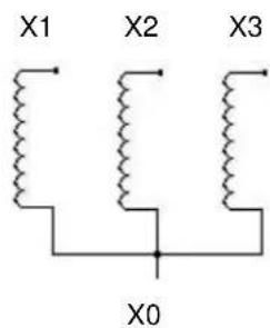
text_image
X1 X2 X3 X0LV Winding

text_image
Y1 Y2 Y3 Y0TERTIARY Winding
DELTA winding configurations:
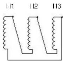
text_image
H1 H2 H3HV Winding
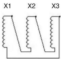
text_image
X1 X2 X3LV Winding

text_image
Y1 Y2 Y3TERTIARY Winding
CAUTION

The specific Test Connections indicated throughout this User Manual are representative of common winding vector relationships. Be sure to check the Transformer Nameplate to ensure the short-circuited winding is, indeed, the LV winding which corresponds to the HV Winding being energized..
Test Connections - Single Phase Transformers:
| SINGLE PHASE, 2 WINDING TRANSFORMER | ||
| TEST NO. | MLR10 Voltage clamps (energize) | Short Circuit Connections |
| 1 | H1-H0 | X1-X0 |
| SINGLE-PHASE, 3 WINDING TRANSFORMER | |||
| TEST NO. | HHV WINDING | XLV WINDING | YTERTIARY WINDING |
| 1 MLR10 V-clamps: H1-H0 Short circuit: X1-X0 Floating | |||
| 2 MLR10 V-clamps: H1-H0 Floating Short circuit: Y1-Y0 | |||
| 3 Floating MLR10 V-clamps: X1-X0 Short circuit: Y1-Y0 | |||
"Per-Phase" Test Connections - Three Phase, 2 Winding Transformers:
| DELTA-WYE | ||
| TEST NO. | MLR10 Voltage Clamps (Energize) | Short Circuit Connections |
| 1 | H1-H3 | X1-X0 |
| 2 | H2-H1 | X2-X0 |
| 3 | H3-H2 | X3-X0 |
| DELTA-DELTA | ||
| TEST NO. | MLR10 Voltage Clamps (Energize) | Short Circuit Connections |
| 1 | H1-H3 | X1-X3 |
| 2 | H2-H1 | X2-X1 |
| 3 | H3-H2 | X3-X2 |
| WYE-DELTA | ||
| TEST NO. | MLR10 Voltage Clamps (Energize) | Short Circuit Connections |
| 1 | H1-H0 | X1-X3 |
| 2 | H2-H0 | X2-X1 |
| 3 | H3-H0 | X3-X2 |
| WYE-WYE | ||
| TEST NO. | MLR10 Voltage Clamps (Energize) | Short Circuit Connections |
| 1 | H1-H0 | X1-X0 |
| 2 | H2-H0 | X2-X0 |
| 3 | H3-H0 | X3-X0 |
"Per-Phase" Test Connections - Three Phase, 3 Winding Transformers:
| DELTA-DELTA-DELTA, THREE-PHASE, 3 WINDING TRANSFORMER | |||
| TEST NO. | HHV WINDING | XLV WINDING | YTERTIARY WINDING |
| 1 MLR10 V-clamps: H1-H3 Short circuit: X1-X3 Floating | |||
| 2 MLR10 V-clamps: H2-H1 Short circuit: X2-X1 Floating | |||
| 3 MLR10 V-clamps: H3-H2 Short circuit: X3-X2 Floating | |||
| 4 MLR10 V-clamps: H1-H3 Floating Short circuit: Y1-Y3 | |||
| 5 MLR10 V-clamps: H2-H1 Floating Short circuit: Y2-Y1 | |||
| 6 MLR10 V-clamps: H3-H2 Floating Short circuit: Y3-Y2 | |||
| 7 Floating MLR10 V-clamps: X1-X3 Short circuit: Y1-Y3 | |||
| 8 Floating MLR10 V-clamps: X2-X1 Short circuit: Y2-Y1 | |||
| 9 Floating MLR10 V-clamps: X3-X2 Short circuit: Y3-Y2 | |||
| DELTA-DELTA-WYE, THREE-PHASE, 3 WINDING TRANSFORMER | |||
| TEST NO. | HHV WINDING | XLV WINDING | YTERTIARY WINDING |
| 1 MLR10 V-clamps: H1-H3 Short circuit: X1-X3 Floating | |||
| 2 MLR10 V-clamps: H2-H1 Short circuit: X2-X1 Floating | |||
| 3 MLR10 V-clamps: H3-H2 Short circuit: X3-X2 Floating | |||
| 4 MLR10 V-clamps: H1-H3 Floating Short circuit: Y1-Y0 | |||
| 5 MLR10 V-clamps: H2-H1 Floating Short circuit: Y2-Y0 | |||
| 6 MLR10 V-clamps: H3-H2 Floating Short circuit: Y3-Y0 | |||
| 7 Floating MLR10 V-clamps: X1-X3 Short circuit: Y1-Y0 | |||
| 8 Floating MLR10 V-clamps: X2-X1 Short circuit: Y2-Y0 | |||
| 9 Floating MLR10 V-clamps: X3-X2 Short circuit: Y3-Y0 | |||
| DELTA-WYE-DELTA, THREE-PHASE, 3 WINDING TRANSFORMER | |||
| TEST NO. | HHV WINDING | XLV WINDING | YTERTIARY WINDING |
| 1 MLR10 V-clamps: H1-H3 Short circuit: X1-X0 Floating | |||
| 2 MLR10 V-clamps: H2-H1 Short circuit: X2-X0 Floating | |||
| 3 MLR10 V-clamps: H3-H2 Short circuit: X3-X0 Floating | |||
| 4 MLR10 V-clamps: H1-H3 Floating Short circuit: Y1-Y3 | |||
| 5 MLR10 V-clamps: H2-H1 Floating Short circuit: Y2-Y1 | |||
| 6 MLR10 V-clamps: H3-H2 Floating Short circuit: Y3-Y2 | |||
| 7 Floating MLR10 V-clamps: X1-X0 Short circuit: Y1-Y3 | |||
| 8 Floating MLR10 V-clamps: X2-X0 Short circuit: Y2-Y1 | |||
| 9 Floating MLR10 V-clamps: X3-X0 Short circuit: Y3-Y2 | |||
| DELTA-WYE-WYE, THREE-PHASE, 3 WINDING TRANSFORMER | |||
| TEST NO. | HHV WINDING | XLV WINDING | YTERTIARY WINDING |
| 1 MLR10 V-clamps: H1-H3 Short circuit: X1-X0 Floating | |||
| 2 MLR10 V-clamps: H2-H1 Short circuit: X2-X0 Floating | |||
| 3 MLR10 V-clamps: H3-H2 Short circuit: X3-X0 Floating | |||
| 4 MLR10 V-clamps: H1-H3 Floating Short circuit: Y1-Y0 | |||
| 5 MLR10 V-clamps: H2-H1 Floating Short circuit: Y2-Y0 | |||
| 6 MLR10 V-clamps: H3-H2 Floating Short circuit: Y3-Y0 | |||
| 7 Floating MLR10 V-clamps: X1-X0 Short circuit: Y1-Y0 | |||
| 8 Floating MLR10 V-clamps: X2-X0 Short circuit: Y2-Y0 | |||
| 9 Floating MLR10 V-clamps: X3-X0 Short circuit: Y3-Y0 | |||
| WYE-DELTA-DELTA, THREE-PHASE, 3 WINDING TRANSFORMER | |||
| TEST NO. | HHV WINDING | XLV WINDING | YTERTIARY WINDING |
| 1 MLR10 V-clamps: H1-H0 Short circuit: X1-X3 Floating | |||
| 2 MLR10 V-clamps: H2-H0 Short circuit: X2-X1 Floating | |||
| 3 MLR10 V-clamps: H3-H0 Short circuit: X3-X2 Floating | |||
| 4 MLR10 V-clamps: H1-H0 Floating Short circuit: Y1-Y3 | |||
| 5 MLR10 V-clamps: H2-H0 Floating Short circuit: Y2-Y1 | |||
| 6 MLR10 V-clamps: H3-H0 Floating Short circuit: Y3-Y2 | |||
| 7 Floating MLR10 V-clamps: X1-X3 Short circuit: Y1-Y3 | |||
| 8 Floating MLR10 V-clamps: X2-X1 Short circuit: Y2-Y1 | |||
| 9 Floating MLR10 V-clamps: X3-X2 Short circuit: Y3-Y2 | |||
| WYE-DELTA-WYE, THREE-PHASE, 3 WINDING TRANSFORMER | |||
| TEST NO. | HHV WINDING | XLV WINDING | YTERTIARY WINDING |
| 1 MLR10 V-clamps: H1-H0 Short circuit: X1-X3 Floating | |||
| 2 MLR10 V-clamps: H2-H0 Short circuit: X2-X1 Floating | |||
| 3 MLR10 V-clamps: H3-H0 Short circuit: X3-X2 Floating | |||
| 4 MLR10 V-clamps: H1-H0 Floating Short circuit: Y1-Y0 | |||
| 5 MLR10 V-clamps: H2-H0 Floating Short circuit: Y2-Y0 | |||
| 6 MLR10 V-clamps: H3-H0 Floating Short circuit: Y3-Y0 | |||
| 7 Floating MLR10 V-clamps: X1-X3 Short circuit: Y1-Y0 | |||
| 8 Floating MLR10 V-clamps: X2-X1 Short circuit: Y2-Y0 | |||
| 9 Floating MLR10 V-clamps: X3-X2 Short circuit: Y3-Y0 | |||
| WYE-WYE-DELTA, THREE-PHASE, 3 WINDING TRANSFORMER | |||
| TEST NO. | HHV WINDING | XLV WINDING | YTERTIARY WINDING |
| 1 MLR10 V-clamps: H1-H0 Short circuit: X1-X0 Floating | |||
| 2 MLR10 V-clamps: H2-H0 Short circuit: X2-X0 Floating | |||
| 3 MLR10 V-clamps: H3-H0 Short circuit: X3-X0 Floating | |||
| 4 MLR10 V-clamps: H1-H0 Floating Short circuit: Y1-Y3 | |||
| 5 MLR10 V-clamps: H2-H0 Floating Short circuit: Y2-Y1 | |||
| 6 MLR10 V-clamps: H3-H0 Floating Short circuit: Y3-Y2 | |||
| 7 Floating MLR10 V-clamps: X1-X0 Short circuit: Y1-Y3 | |||
| 8 Floating MLR10 V-clamps: X2-X0 Short circuit: Y2-Y1 | |||
| 9 Floating MLR10 V-clamps: X3-X0 Short circuit: Y3-Y2 | |||
| WYE-WYE-WYE, THREE-PHASE, 3 WINDING TRANSFORMER | |||
| TEST NO. | HHV WINDING | XLV WINDING | YTERTIARY WINDING |
| 1 MLR10 V-clamps: H1-H0 Short circuit: X1-X0 Floating | |||
| 2 MLR10 V-clamps: H2-H0 Short circuit: X2-X0 Floating | |||
| 3 MLR10 V-clamps: H3-H0 Short circuit: X3-X0 Floating | |||
| 4 MLR10 V-clamps: H1-H0 Floating Short circuit: Y1-Y0 | |||
| 5 MLR10 V-clamps: H2-H0 Floating Short circuit: Y2-Y0 | |||
| 6 MLR10 V-clamps: H3-H0 Floating Short circuit: Y3-Y0 | |||
| 7 Floating MLR10 V-clamps: X1-X0 Short circuit: Y1-Y0 | |||
| 8 Floating MLR10 V-clamps: X2-X0 Short circuit: Y2-Y0 | |||
| 9 Floating MLR10 V-clamps: X3-X0 Short circuit: Y3-Y0 | |||
"Three-Phase Equivalent" Connections – Three Phase, 2 Winding Transformers
Lead connections, for Three-Phase Equivalent testing of 2-winding Transformers, are as shown in Table B and are applicable to all Transformer configurations as shown below in Table A.
| TABLE A | |
| HHV WINDING | XLV WINDING |
| DELTA | DELTA |
| DELTA | WYE |
| WYE DELT | A |
| WYE WYE | |
| TABLE B | ||
| TEST NO. ML | R10 VOLTAGE CLAMPS (ENERGIZE) | SHORT-CIRCUIT CONNECTIONS |
| 1 | H1-H3 | X1-X2-X3 |
| 2 | H2-H1 | X1-X2-X3 |
| 3 | H3-H2 | X1-X2-X3 |
"Three-Phase Equivalent" Test Connections – Three Phase, 3 Winding Transformers.
Lead connections, for Three-Phase Equivalent testing of 3-winding Transformers, are as shown in Table D and are applicable to all Transformer configurations as shown in Table C.
| TABLE C | ||
| HHV WINDING | XLV WINDING | YTERTIARY WINDING |
| DELTA DELT | A | DELTA |
| DELTA | DELTA | WYE |
| DELTA | WYE | DELT A |
| DELTA | WYE | WYE |
| WYE | DELTA | DELTA |
| WYE | DELTA | WYE |
| WYE | WYE | DELTA |
| WYE | WYE | WYE |
| TABLE D | |||
| TEST NO. | H HV WINDING | X LV WINDING | Y TERTIARY WINDING |
| 1 MLR10 V-clamps: H1-H3 Short circuit: X1-X2-X3 Floating | |||
| 2 MLR10 V-clamps: H2-H1 Short circuit: X1-X2-X3 Floating | |||
| 3 MLR10 V-clamps: H3-H2 Short circuit: X1-X2-X3 Floating | |||
| 4 MLR10 V-clamps: H1-H3 Floating Short circuit: Y1-Y2-Y3 | |||
| 5 MLR10 V-clamps: H2-H1 Floating Short circuit: Y1-Y2-Y3 | |||
| 6 MLR10 V-clamps: H3-H2 Floating Short circuit: Y1-Y2-Y3 | |||
| 7 Floating MLR10 V-clamps: X1-X3 Short circuit: Y1-Y2-Y3 | |||
| 8 Floating MLR10 V-clamps: X2-X1 Short circuit: Y1-Y2-Y3 | |||
| 9 Floating MLR10 V-clamps: X3-X2 Short circuit: Y1-Y2-Y3 | |||
Leakage Reactance Test Procedure
- Using the supplied green ground cable, connect the MLR10 ground terminal to a suitable earth ground.
- Make sure the AC mains switch is set to its OFF position and then connect the supplied AC mains cord to connect to a 120VAC power source.
- Attach each of the two 15 meter Output Voltage cables to either of the MLR10 front panel receptacles, by pushing and turning (in the clockwise direction), to ensure they both are fully engaged.
IMPORTANT NOTE: Output cables should be uncoiled for maximum measurement accuracy.
- Using the supplied USB cable, connect the MLR10 to the companion computer (PC laptop, Delta 3000, etc).
- Power up the computer and run the MLR10 software. A message box will pop up and say that an MLR10 has been detected. Click OK to bring up the main screen as shown in Figure E-3. Be sure that the VI Calibration factors, associated with the MLR10 being used, are what are stored in the software being used on the PC (See Cal Factor Loading routine of Section 3).
- Open the drop down box in the upper right corner and select the Leakage Reactance Test. Then, enter Base KVA and Base Voltage into the green zone on the screen. This data may be obtained from the transformer nameplate. Then, for reference points, enter the % Impedance and % Reactance (from either the most recent test data-file or from the transformer nameplate, if available/known). The target Test Current is also calculated from these values and shown in red on the screen.
- With the AC power breaker set to the OFF positions, and with the voltage knob turned all the way down to the zero volts position (fully counter-clockwise), the operator may then attach the output cable red clamps to the transformer under test. Both clamps should be assumed to be at High Voltage and, as such, the necessary Safety Precautions should be taken, as outlined in this Manual.
-
With the Voltage knob in the zero volts position (as described in Sections 7 and 8, above), turn the AC mains switch to the ON position. The green lamp will turn on. Press the red High Voltage Enable button. The red lamp will turn on. Slowly turn the voltage knob until the displayed current is approximately the same as the target Test Current. Both the meters and the numeric displays in the blue zone on the screen may be used to monitor voltage and current. If the target Test Current cannot be reached, set the voltage control to maximum.
-
To complete the test and obtain the readings, click the red Test button on the screen. The resultant data set including Impedance, Resistance, Reactance, Inductance, % Impedance, Delta % Impedance, % Reactance, and Delta % Reactance will then be displayed in the red zone. Also, the Power and Power Factor calculations will be displayed in the blue zone on the screen.
-
Next, turn the voltage control knob all the way down to zero volts (counterclockwise) and then, switch the AC mains switch to the OFF position. Lastly, taking the precautions as outlined in Section 7 above, disconnect all leads from the Unit Under Test.
-
To exit the MLR10 software application, click on the QUIT button on the screen.

text_image
MLR10 Control Software 2.0 Megger MLR10 Leakage Reactance Test Base KVA 10.0 Base Voltage 10000 % Impedance 1.00 % Reactance 1.00 Target Output Current 1.0 TEST QUIT Output Voltage 50 100 150 200 250 300 Output Current Test Voltage (volts) Test Current (amps) Power (watts) Power Factor (%) Impedance (ohms) 0.0 Resistance (ohms) 0.0 Reactance (ohms) 0.0 Inductance (mH) % Impedance 0.00 Delta % Impedance 0.00 % Reactance 0.00 Delta % Reactance 0.00 System Info Probe Calibration VI CalibrationFigure 3. Leakage Reactance Test Screen
Capacitor Bank Test Procedure
With the use of the MLR10's optional CT clamp, electrical measurements can be isolated to individual legs of a complex capacitive bank network or to the entire bank. As shown in Figure E-4 below, the MLR10 AC Voltage source is applied across the appropriate capacitor section (containing the capacitor of interest) and the optional CT clamp can be used to isolate the measurements specific to the capacitor of interest as depicted below.
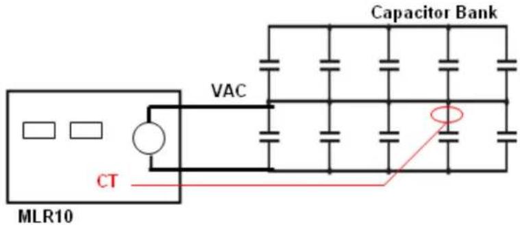
text_image
Capacitor Bank VAC CT MLR10Figure 4. Capacitor Bank Test Connection (isolated leg shown above)
- Using the supplied green ground cable, connect the MLR10 ground terminal to a suitable earth ground.
- Make sure the AC mains switch is set to its OFF position and then connect the supplied AC mains cord to connect to a 120VAC power source.
- Attach each of the two 15 meter Output Voltage cables to either of the MLR10 front panel receptacles, by pushing and turning (in the clockwise direction), to ensure they both are fully engaged. Also, at this point, attach the Capacitor Bank test probe to the MLR10.
IMPORTANT NOTE: Output cables should be uncoiled for maximum measurement accuracy.
- Using the supplied USB cable, connect the MLR10 to the companion computer (PC laptop, etc).
- Power up the computer and run the MLR10 software. A message box will pop up and say that an MLR10 has been detected. Click OK to bring up the main screen as shown in Figure E-5.
-
Open the drop down box in the upper right corner and select the Capacitance Test. At this point, the unused fields (unique to the Leakage Reactance testing) will be disabled.
-
With the AC power breaker set to the OFF positions, and with the voltage knob turned all the way down to the zero volts position (fully counter-clockwise), the operator may then attach the Output Voltage clamps to the Capacitor bank, which contains the capacitor of interest (or to the MLR10's VAC lead if the capacitance of the entire bank is of interest). Both clamps should be assumed to be at High Voltage and, as such, the necessary Safety Precautions should be taken, as outlined in this Manual.
- With the Voltage knob in the zero volts position (as described in Sections 7 and 8, above), turn the AC mains switch to the ON position. The green lamp will turn on. Press the red High Voltage Enable button. The red lamp will turn on. Slowly turn the voltage knob until the displayed current is approximately the same as the target Test Current. Both the meters and the numeric displays in the blue zone on the screen may be used to monitor voltage and current. If the target Test Current cannot be reached, set the voltage control to maximum. Next, prior to connecting the Capacitor Bank CT probe to the capacitor of interest, a quick calibration routine should be performed. Click the Probe Calibration button on the PC. A window opens asking the user to clip the current probe around either of the output voltage cables. This can be done anywhere along the cable but it's convenient to clamp right around one of the output connectors on the MLR10. When the probe is on, press OK to continue (if the probe is clipped on backwards, a window will open and tell you to reverse it). After clicking OK, a window then opens telling you that the calibration procedure is complete. The clamp on probe may then be removed and placed on the capacitor of interest and the test continued.
- To complete the test and obtain the measured readings, click the red Test button on the screen. The resultant data set including Impedance, Resistance, Reactance, and Capacitance will then be displayed in the red zone on the screen. Also, the Power and Power Factor calculations will be displayed in the blue zone on the screen.
- Next, turn the voltage control knob all the way down to zero volts (counterclockwise) and then, switch the AC mains switch to the OFF position. Lastly, taking the precautions as outlined in Section 7 above, disconnect all leads from the Unit Under Test.
- To exit the MLR10 software application, click on the QUIT button on the screen.

text_image
MLR10 Control Software 2.0 Megger MLR10 Capacitance Test Base KVA 10.0 Base Voltage 10000 % Impedance 1.00 % Reactance 1.00 Target Output Current 10.0 TEST QUIT Output Voltage 50 100 150 200 250 300 Output Current 5 10 15 20 25 Test Voltage (volts) Test Current (amps) Power (watts) Power Factor (%) Impedance (ohms) Resistance (ohms) Reactance (ohms) Capacitance (uF) % Impedance Delta % Impedance % Reactance Delta % Reactance System Info Probe Calibration VI CalibrationFigure 5. Capacitance Test Screen
5
Repair
Megger offers a complete repair and calibration service and recommends that its customers take advantage of this service in the event of equipment malfunction. Contact your MEGGER representative for instructions and a return authorization (RA) number. Equipment returned for repair should be shipped prepaid and insured and marked for the attention of the Repair Department. Please indicate all pertinent information including problem symptoms and attempted repairs. The catalog number and serial number of the equipment should also be specified. Pack the MLR10, including all cables, in a carton (original shipping carton if available) with adequate dunnage in accordance with best commercial practice. Seal the carton with waterproof tape.
Ship to: Megger
Valley Forge Corporate Center
2621 Van Buren Avenue
Norristown,
PA
19403
U.S.A.
Megger.