
CDAX 605 - Measurement Megger - Free user manual and instructions
Find the device manual for free CDAX 605 Megger in PDF.

| Product Type | High-voltage capacitance and dissipation factor bridge for laboratory, production, or field testing |
| Dimensions (Instrument) | 335 x 300 x 99 mm (13.2 x 11.8 x 3.9 in) |
| Dimensions (Transport Case) | 520 x 430 x 220 mm (20.5 x 16.9 x 8.7 in) |
| Weight | 4.4 kg (9.7 lb) |
| Power Supply | 100–240 V AC, 50/60 Hz, ±10%, max. 60 VA |
| Measurement Parameters | Capacitance, dissipation factor (tan δ), inductance, phase angle, voltage, current; ratio measurements |
| Test Frequency | 5 – 500 Hz |
| Measurement Range (Capacitance) | >0.01 pF (max depends on voltage) |
| Measurement Range (Dissipation Factor) | 0 – 100 (0 – 10 within specified accuracy) |
| Current Range | 15 μA – 5 A (extendable with external CT) |
| Accuracy (Capacitance) | ±0.02% at currents <300 mA; ±0.1% at 300–1000 mA |
| Accuracy (Dissipation Factor) | ±(0.05% of reading + 2×10⁻⁵) at <300 mA; ±(0.05% of reading + 5×10⁻⁵) at 300–1000 mA |
| Resolution (Capacitance) | 0.001 pF |
| Measurement Time | Selectable (default 5 s) |
| Warm-up Time | 30 min for full accuracy |
| Operating Temperature | −20 to +55 °C (−4 to +131 °F) |
| Humidity | 0 – 90% non-condensing |
| PC Interface | Ethernet (recommended) or USB |
| Software Included | CDAX605 Control (Windows XP/Vista/7/8) |
| Safety | CE marked, IEC 61010, CSA C22.2 No. 61010-1; high-voltage safety precautions required |
| Maintenance | Disconnect mains before cleaning; clean with detergent and water; cables with isopropyl alcohol; yearly calibration recommended |
| Warranty | One year against defects in material and workmanship |
| Fuse | 2AT slow blow 5×20 mm (Littlefuse or similar) |
Frequently Asked Questions - CDAX 605 Megger
User questions about CDAX 605 Megger
0 question about this device. Answer the ones you know or ask your own.
Ask a new question about this device
Download the instructions for your Measurement in PDF format for free! Find your manual CDAX 605 - Megger and take your electronic device back in hand. On this page are published all the documents necessary for the use of your device. CDAX 605 by Megger.
USER MANUAL CDAX 605 Megger
Copyright© 2014 by Megger. All rights reserved.
Article no: ZP-AI01AE
V01a
The contents of this manual are the property of Megger Sweden AB. No part of this work may be reproduced or transmitted in any form or by any means, except as permitted in written license agreement with Megger Sweden AB. Megger Sweden AB has made every reasonable attempt to ensure the completeness and accuracy of this document. However, the information contained in this manual is subject to change without notice, and does not represent a commitment on the part of Megger Sweden AB. Any attached hardware schematics and technical descriptions, or software listings that disclose source code, are for informational purposes only. Reproduction in whole or in part to create working hardware or software for other than Megger Sweden AB products is strictly prohibited, except as permitted by written license agreement with Megger Sweden AB.
TRADEMARK NOTICES
Megger® and Programma® are trademarks registered in the U.S. and other countries. All other brand and product names mentioned in this document are trademarks or registered trademarks of their respective companies. Megger Sweden AB is certified according to ISO 9001 and 14001.
Content
1 Overview 3
1.1 General 3
1.2 Measurement principle 3
2 Specification....3
3 Safety....5
3.1 General 5
3.2 Instrument symbols 5
3.3 Warning and Caution Notices....6
3.3.1 Warning 6
3.3.2 Caution 6
3.4 General safety information 6
3.5 Instrument safety 7
4 Maintenance 8
5 Warranty....8
5.1 Receiving Instructions 8
5.2 Warranty 8
5.3 Warranty repair....8
6 Control, indicators and connectors 9
6.1 Front panel....9
6.2 Back panel 10
7 Software Installation....11
8 CDAX605 Control 11
8.1 Connect.... 11
8.2 Control tab....12
8.3 Settings tab 14
9 Calibration....16
9.1 Warm-up.... 16
9.2 Calibration procedure 16
9.2.1 Calibration 17
9.2.2 Balancing....17
10 Operating instructions 17
10.1 Standard test circuits.... 17
10.1.1 Ungrounded Specimen Test (UST) with grounded HV Supply.... 17
10.1.2 Ratio transformer with grounded HV supply.... 20
10.1.3 Grounded Specimen Test (GST) with floating HV Supply 21
10.2 Measurements with Test Current greater than 5A (with external current transformer)....22
10.2.1 General information on Range Extension.... 22
10.2.2 Errors caused by an external CT 22
11 Stored data and reporting.... 23
12 User fields.... 23
12.1 Editing user fields 24
12.1.1 Description of buttons 24
12.1.2 User field parameters.... 24
12.1.3 Entering a formula.... 26
12.1.4 Example – Creating a user field showing correction factor 27
12.2 The Results Window 27
1 Overview
1.1 General
CDAX605 is a measurement instrument that is used with a separate AC power source and a reference capacitor to form a complete measurement setup. It is a precision instrument using direct measurement for fast data acquisition in combination with an internal balancing circuit that secures a very high accuracy in line with traditional ratio-arm bridges. CDAX605 is designed for laboratory, production line or field testing of electrical equipment insulation and insulating materials as well as e.g. calibration of CCVTs and other ratio devices. A test set with unique high accuracy for the most demanding applications.
Testing can be performed at almost any voltage level pending on the rating of the equipment, the power source and the capacitor. The unit has full accuracy from current as low as 15 A and will accept a test current up to 5 A from the insulation under test. The test current may be increased by use of an external current transformer. CDAX605 is designed to be able to directly replace the (obsolete) Multi-Amp CB-605 High-voltage capacitance and dissipation factor bridge.
Traditional bridge methods can only measure and compare capacitive currents and since calibrated reference capacitors are typically available in the 100 to 1000 pF range, precision measurements on e.g. CCVTs and other devices with a high ratio may be difficult to perform. With the new technology in CDAX605, the input voltage to the device can be measured with a traditional reference capacitor while the secondary low voltage can be measured either with a second reference capacitor or with a reference resistor that is designed to give appropriate measurement current. Nor reference capacitors or resistors are included in a standard delivery.
1.2 Measurement principle
CDAX measuring system is based on the so called “double vector-meter method”. Measurement of the current I_N through a known standard capacitor C_N and current I_x through an unknown test object C_x . Both branches are energized by an external HV AC power source ( U_Test ) and both currents are measured by high accuracy ammeters. Based on the data coming from the known standard capacitor all desired measuring values can be determined directly without any manual interaction.
The accuracy of the unit is based on “ammeter similarity”. If the ammeters are identically in all aspects, the inaccuracy of the system is zero. To ensure similarity during various operating conditions, an internal balancing circuitry can be activated to run automatically or on command. The results from the balancing check are if necessary used to adjust range gain settings to ensure that the two channels are similar over the measurement range.
2 Specification
The CDAX is intended for indoor use but can also be used outdoors but not in wet conditions (e.g. rain or high humidity, see Relative humidity below for more details). As accuracy of capacitance and ratio (not phase and dissipation factor) is affected by temperature, a stable environment regarding temperature is essential for accurate readings. To achieve maximum accuracy, turn on the unit and allow the unit to adjust to the ambient temperature for at least 30 minutes before first balancing. After balancing, specified accuracy will be achieved.
| Parameter | Specification | Comment | |
| General | Dimensions | 335 x 300 x 99 mm(17.7" x 16.1" x 6.3") | Instrument |
| Dimensions | 520 x 430 x 220 mm(20.5" x 17.0" x 8.7") | Transport case | |
| Weight | 4.4 kg (9.7 lbs) | Instrument only | |
| Mains voltage | 100 - 240 V AC, 50/60 Hz | ± 10 % | |
| Power consumption | 60 VA (max) | ||
| Measurement channels | 2 | 2 physical ammeters | |
| Measurement inputs | 4 | Reference, Input 1 (red), Input 2 (blue) and Ground | |
| Test Modes | 7 | UST-R, UST-B, UST-RB, GST-GND, GSTg-R, GSTg-B, GSTg-RB | |
| Test frequency | 5 - 500 Hz | ||
| Measurement range | Capacitance | >0.01 pF | Max capacitance is a function of applied voltage |
| Inductance, Lp | < 1 MH | Min inductance is a function of applied voltage | |
| Dissipation factor | 0 - 100 | 0 - 10 within specified accuracy | |
| Voltage | Unlimited | Pending reference capacitor value only | |
| Current | 15 μA - 5 A | Can be increased by using an external current transformer. | |
| Phase | 0 - 360°/0-2π mrad | ||
| Accuracy (* | Capacitance | ± 0.02% | At reference and test currents < 300mA |
| ± 0.1% | At reference and test currents 300-1000 mA | ||
| Inductance | ± 0.1 % | ||
| Voltage/current | ± 0.5% of reading | Absolute voltage/current reading | |
| Dissipation factor | ± (0.05% of reading + 2 × 10^-5) | At reference and test currents < 300mA | |
| ± (0.05% of reading + 5 × 10^-5) | At reference and test currents 300-1000 mA | ||
| Phase | ± 0.02 mrad | At reference and test currents < 300mA | |
| ± 0.05 mrad | At reference and test currents 300-1000 mA | ||
| Voltage/current | ± 0.5% of reading | Absolute voltage/current reading | |
| Max resolution | Capacitance | 0.001 pF | |
| Inductance | 0.1 mH | ||
| Dissipation factor | 1 × 10^-6 | ||
| Phase | 1 × 10^-6 Rad | ||
| Measurement time | Selectable, default 5 s | ||
| Warm-up time | 30 min | ||
| Temperature range | Operating | -20 - 55°C (-4 - 131°F) | |
| Storage | -40 - 70°C (-40 - 158°F) | ||
| Humidity | Operating | 0 to 90% non-condensing | |
| Calibration | Absolute calibration and manual or automatic amplitude balancing | Recommended interval for absolute calibration is 1 year | |
| SW | CDAX605 Control | Reference data entryCapacitance/inductanceResistanceDissipation factorPhase (Rad or min)Ratio measurementsData log/storageData export (cut & paste) | Optional LabView and C# interface |
| PC requirements | Pentium 500 MHz/512 Mb or better. Windows XP, Vista, 7 or 8 | ||
| Communication | Ethernet (recommended) or USB | High quality shielded Ethernet cable or USB cable with ferrite choke | |
| CE marking | LVD: IEC 61010EMC: IEC 61326 | ||
*) Accuracy values are valid under the following conditions:
- Internal balancing performed after minimum 30 min warm-up
• Test generator frequency 50/60Hz
• THD of power source <10%
- UST measurement
• Measurement (averaging) time 5 s
- Ambient temperature 23^ C ± 5^
• Magnetic field at measurement frequency < 5 μT
3 Safety
3.1 General

IMPORTANT
Read and comply with the following instructions.
Always comply with local safety regulations.
3.2 Instrument symbols

Caution, refer to the accompanying documents, e.g. User Manual.

Protective conductor terminal.

Guard terminal used for GST measurements only. The terminal must be at ground potential and the symbol indicates that a hazardous live voltage must not be connected to the guard terminal.

WEEE, Waste Electrical and Electronic Equipment. Please utilize your local WEEE collection facilities in the disposition of this product and otherwise observe all applicable requirements.
CE
CE marking indicates that the product fulfills all applicable EU requirements.
①
Marking indicates that the product fulfills the requirements in stated in CAN/CSA C22.2, No. 61010-1, 2^nd edition including Amendment 1.
3.3 Warning and Caution Notices
Warning and caution notices are used throughout this manual where applicable and should be strictly observed. These notices appear in the format shown below and are defined as follows:
3.3.1 Warning
Warning, as used in this manual, is defined as a condition or practice which could result in personal injury or loss of life.
3.3.2 Caution
Caution, as used in this manual, is defined as a condition or practice which could result in damage to or destruction of the equipment or apparatus under test.
3.4 General safety information
The test set and the specimen to which it is connected are a possible source of high-voltage electrical energy and all persons making or assisting in tests must use all safety practice precautions to prevent contact with energized parts of the test equipment and related circuits.
Persons actually engaged in the test must stand clear of all parts of the complete high-voltage circuit, including all connections, unless the test set is de-energized and all parts of the test circuit are grounded. Persons not directly involved with the work must be kept away from test activities by suitable barriers, barricades, or warnings.
Treat all terminals of high-voltage power equipment as a potential electric shock hazard. There is always the potential of voltages being induced at these terminals because of proximity to energized high-voltage lines or equipment.
Always use a safety ground stick to ground the high-voltage conductor. Always disconnect test leads from power equipment before attempting to disconnect them from the test set. The ground connection must be the first made and the last removed. Any interruption of the grounding connection can create an electric shock hazard.
It is not possible to eliminate all potential hazards from, and in using, electrical test equipment. For this reason, every effort has been made to point out in this instruction manual the proper procedures and precautions to be followed by the user in operating this equipment and to mark the equipment itself with precautionary warnings where appropriate. It is not possible to foresee every hazard which may occur in the various applications of this equipment. It is therefore essential that the user, in addition to following the safety rules in this manual, also carefully consider all safety aspects of the test before proceeding.
High-voltage discharges and other sources of strong electric or magnetic fields may interfere with the proper functioning of heart pacemakers. Persons with heart pacemakers should obtain expert
advice on the possible risks before operating this equipment or being close to the equipment during operation.
3.5 Instrument safety
This instrument operates from a single-phase power source. It has a three-wire power cord and requires a two-pole, three-terminal, live, neutral, and ground type connector. The voltage of the power source must be within the following rated operating voltage: 100-240 V ± 10 %, 50/60 Hz.
Before making connection to the power source, determine that the instrument rating matches the voltage of the power source and has a suitable two-pole, three-terminal grounding connector. The power input plug must be inserted only into a mating receptacle with a ground contact. Do not bypass the grounding connection. Any interruption of the grounding connection can create an electric shock hazard. Determine that the receptacle is properly wired before inserting the plug.
The test voltage which is reported by the instrument depends on the entered reference capacitance value. Also, during self-calibration, the instrument will not be indicating if high voltage is present. Never use the reported high voltage reading as an indicator whether high voltage is present. Always make sure that other safeguards exist so that the maximum allowable voltage cannot be exceeded due to incorrect readings from the instrument.
All persons making or assisting in tests must use all practical safety precautions to prevent contact with energized parts of the test equipment and related circuits. Also follow all local and company safety requirements. Persons actually engaged in the test must stand clear of all parts of the complete high-voltage circuit, including all connections, unless the test set is de-energized and all parts of the test circuit are grounded. Persons not directly involved with the work must be kept away from test activities by suitable barriers, barricades, or warnings.
• Safety is the responsibility of the user.
- Misuse of this high-voltage equipment can be extremely dangerous.
- The purpose of this equipment is limited to use as described in this manual. Do not use the equipment or its accessories with any device other than specifically described.
- Make sure that the instrument is properly grounded, both through its AC power cord and through the test ground connector.
• Never connect the test set to energized equipment.
- Before making any connections, make sure that the high voltage generator is de-energized and that all parts of the test circuit are properly grounded.
- Always disconnect test leads from test specimen before attempting to disconnect them at the test set.
- The ground connection on the test set must be the first made and the last removed. Any interruption of the grounding connection can create an electric shock hazard.
• Operation is prohibited in rain or snow.
- Do not use the test set in an explosive atmosphere.
- A qualified operator should be in attendance at all times while the test equipment is in operation.
- Observe all safety warnings marked on the equipment.
- Corrective maintenance must only be performed by qualified personnel who are familiar with the design and operation of the test set and the hazards involved.
- Refer to IEEE 510 - 1983, “IEEE Recommended Practices for Safety in High-Voltage and High-Power Testing,” for information.
4 Maintenance
• DISCONNECT the MAINS plug before any cleaning or maintenance.
- Maintenance should be performed only by qualified personell familiar with the hazards involved with high-voltage test equipment.
- Read and understand Safety in the User Manual before performing any service.
- Routine maintenance is all that is required for these test sets. The cables and connector panel should be inspected frequently to be sure all connections are tight and all ground connections intact.
- The appearance of the test set can be maintained by occasional cleaning of the case, panel and cable assemblies. The outside of the carrying case can be cleaned with detergent and water. Dry with a clean, dry cloth. The control panel can be cleaned with a cloth dampened with detergent and water. Do not allow water to penetrate panel holes, because damage to components on the underside may result. A household all-purpose spray cleaner can be used to clean the panel. Polish with a soft, dry cloth, taking care not to scratch the display screen cover. The cables and mating panel receptacles can be cleaned with isopropyl or denatured alcohol applied with a clean cloth.
5 Warranty
5.1 Receiving Instructions
- Check the equipment received against the packing list to ensure that all materials are present. Notify Megger of any shortage.
- Examine the instrument for damage received in transit. If damage is discovered, file a claim with the carrier at once and notify Megger, giving a detailed description of the damage.
- This instrument has been thoroughly tested and inspected to meet rigid specifications before being shipped. It is ready for use when set up as indicated in this user manual.
5.2 Warranty
- Products supplied by Megger are warranted against defects in material and workmanship for a period of one year following shipment.
- Our liability is specifically limited to replacing or repairing, at our option, defective equipment.
- This warranty does not include batteries, lamps or other expendable items, where the original manufacturer's warranty shall apply.
- We make no other warranty. The warranty is void in the event of negligence abuse (failure to follow recommended operating procedures) or failure by the customer to perform specific maintenance as indicated in this manual.
5.3 Warranty repair
• Equipment returned to the factory for repair must be shipped prepaid and insured.
- Contact your Megger representative for instructions and a return authorization (RA) number.
- Please indicate all pertinent information, including problem symptoms.
• Also specify the serial number and the catalog number of the unit.
6 Control, indicators and connectors
6.1 Front panel
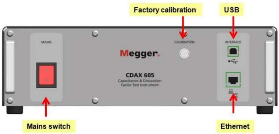
On/off
Calibration
USB/B
Ethernet
Mains switch, single pole switch, On = right, Off = left, see symbol on panel Used for factory calibration only
Controlling the CDAX from a PC using USB (USB cable with ferrite choke)
Controlling the CDAX from a PC or using Ethernet (shielded Ethernet cable) Ethernet communication is recommended due to better protection against high interference.
6.2 Back panel
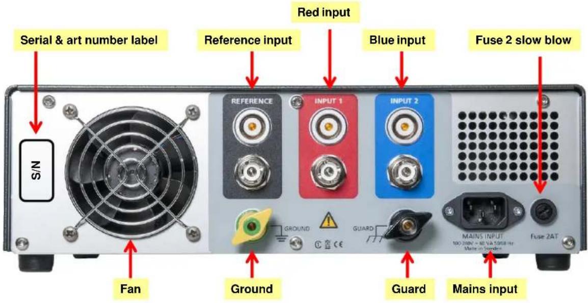
| Label | Article number (AI-19070) and serial number (YYXxxxx) |
| Reference | Input for reference (normal) capacitor, Lemo and UHF connectors in parallel |
| Input 1 | Red input, Lemo and UHF connectors in parallel |
| Input 2 | Blue input, Lemo and UHF connectors in parallel |
Input adapter Three UHF to BNC adapters are delivered as a standard accessory making it possible to use BNC cables instead of UHF.
| Mains input | 100-240 V AC, 50/60 Hz, max 60 VA, disconnecting device |
| Fuse | 2AT slow blow 5x20 mm fuse, Littlefuse or similar |
| Ground | Connector for attaching CDAX to protective ground |
| Guard | Connector for attaching CDAX to guard when doing GST measurementsA jumper is delivered with the unit between Ground and Guard.Note: If a jumper is connected between ground and guard, it must be removed when performing GST measurements! |
7 Software Installation
To start installing the software, insert the USB memory stick and run the program CDAX 605 install program. Follow instructions on the screen.
8 CDAX605 Control
8.1 Connect
Connect the PC to CDAX using the Ethernet cable. When you start the CDAX605 software it will try to connect to a CDAX605 unit. When the dialog is displayed you can select which CDAX605 unit you want to connect to. You can either select it in the list of found instruments or enter the IP address. You may also select to always try to connect to that specific unit.

It is possible to communicate between CDAX and the PC using USB, but this is mainly used while updating software in an office environment.
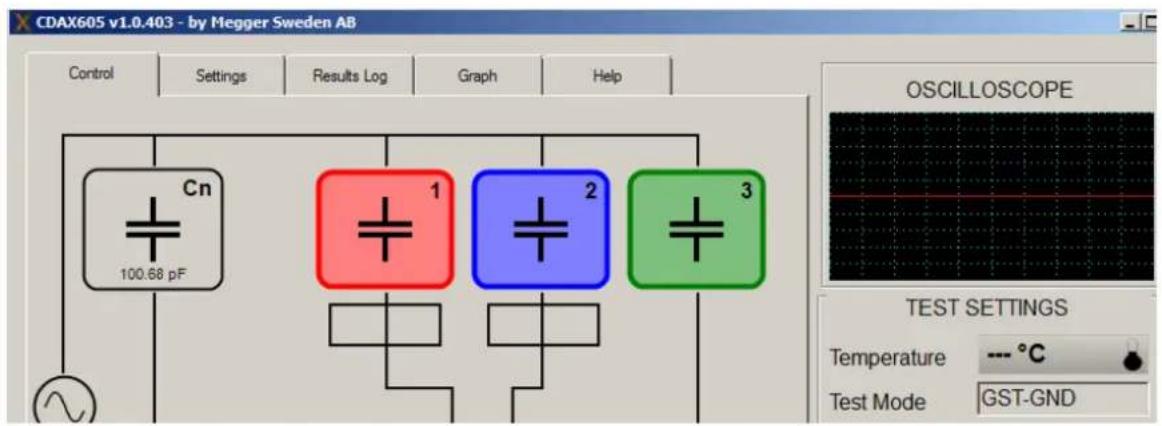
8.2 Control tab
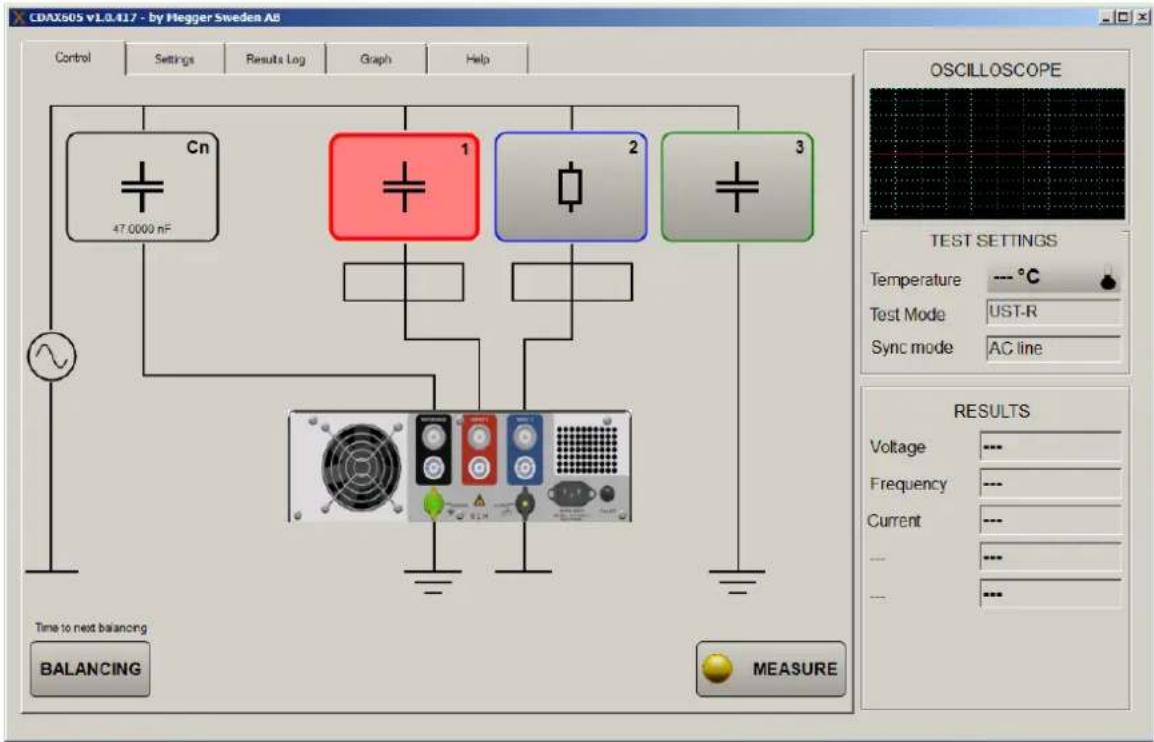
The main screen tab is the tab shown at start-up and the screen used for measuring.
By activating one or several buttons/measurement channels 1, 2, 3 the instrument is put in the different standard test modes. CDAX supports the following test modes:
| UST: Ungrounded Specimen Testing | |||
| Test mode | Measure | Ground | Guard |
| UST-R | Red | Blue | --- |
| UST-B | Blue | Red | --- |
| UST-RB | Red and Blue | --- | --- |
| GST: Grounded Specimen Testing | |||
| Test mode | Measure | Ground | Guard |
| GST-GND | Ground | Red and Blue | --- |
| GSTg-R | Ground | Blue | Red |
| GSTg-B | Ground | Red | Blue |
| GSTg-RB | Ground | --- | Red and Blue |
As an example, activating all channels puts the instrument in GST-GND mode.
Continuous measurements are shown in the "Results" part
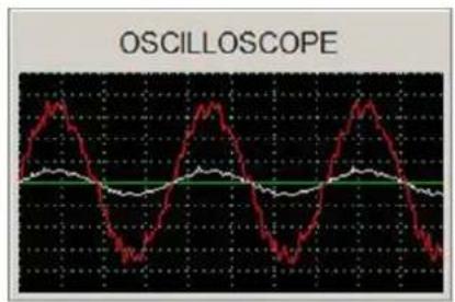
The Oscilloscope displays the signal (white) proportional to current in reference (Cn) arm and the signal (red) proportional to the measured current (red), e.g. in Cx1-arm. Since the “ampere-meters” have 4 gain steps, the proportional constant varies in steps increasing the currents. The oscilloscope time base is automatic
To start an individual measurement press "Measure"
To manually start a balancing check press "Balancing"
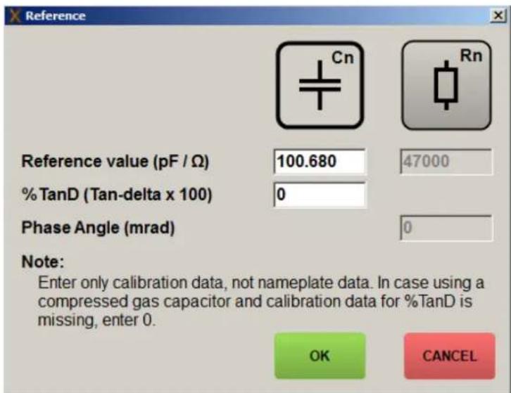
8.3 Settings tab
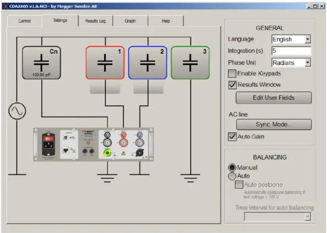
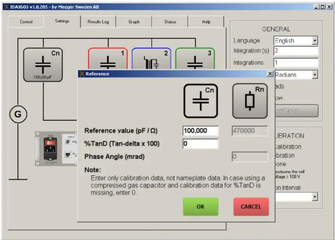
Clicking on the reference brings up the reference dialog where you can change the type and value; Typically, a zero dissipation factor is used for compressed gas filled reference capacitor, but it is possible to add a dissipation factor of the reference capacitor if e.g. a reference polystyrene capacitor is used. Note that accuracy of measurement, and possible temperature dependence, depends very much of type of reference and most accurate results are achieved by use of standard compressed gas capacitor.
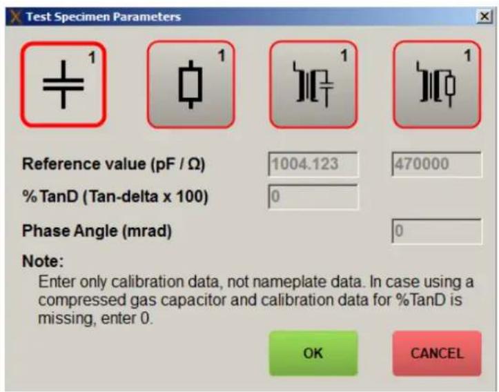
Clicking on one of the test specimens makes it possible to change its settings.
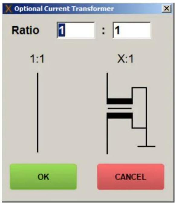
Clicking one of the squares on the red/blue connection “leads” brings up the options for using an external current transformer.
Synchronization mode:
CDAX measures fundamental frequency of reference, Cn, current and sample current using a filter with a bandwidth of ±6 Hz/s of integration. E.g. using 5 s of integration, the bandwidth is ±1.2 Hz. CDAX supports three synchronization modes that are selected by press the “Sync. Mode...-button”.

- AC line means that the mains frequency of the CDAX unit is measured continuously and the frequency is used as synchronization frequency. This is the best choice when the unit is used with a test generator supplied form the AC mains.
- Reference input means that the reference input signal is measured and used for synchronization. You need to set an approximate synchronization frequency (e.g. 50, 60 or 400 Hz). Note: Reference current must be >30 μA for synchronization
- No synchronization means that the CDAX system measures using set frequency for synchronization regardless of AC line frequency or applied frequency on reference input. You must set a frequency near the actual frequency.
In most measurement setups, CDAX is measuring a capacitive object and using a standard capacitor on the reference input. In those situations, “No synchronization” works well and gives fast updates of displayed results.
However when measuring a mixed setup, e.g. ratio with a standard capacitor as reference and a reference resistor on secondary, the frequency is of utmost importance for accuracy in ratio values and synchronized mode must be used.
9 Calibration
9.1 Warm-up
To achieve maximum accuracy, turn on the unit and allow the unit to adjust to the ambient temperature for at least 30 minutes and a balancing is performed.
9.2 Calibration procedure
System calibration is made up of two routines: Calibration, typically performed every year, and manual or automatic amplitude balancing, performed in the field after warm-up and at customer defined intervals.
The calibration for amplitude and phase should be performed at the recommended calibration interval of the system, i.e. every year. Amplitude balancing is performed when asked for or automatically by the instrument at intervals specified by the user. During amplitude balancing the
instrument checks that (and if necessary adjust for) the two measuring channels, reference and specimen input, are similar.
The balancing procedure is controlling the accuracy of relational measurements such as capacitance and ratio. Calibration is confirming phase and dissipation factor measurements as well as absolute readings of the two measurement channels, i.e. voltage and current readings.
9.2.1 Calibration
Calibration is performed using the MIX utility software. The required hardware for performing a complete absolute calibration is, apart from the system itself, a calibrated Digital Multi Meter (DMM) with adequate accuracy. The procedure is fully documented in the MIX utility software. A few points are however worthwhile to note:
- It is convenient to store the calibration data also outside of the instrument for future reference.
- For highest accuracy, make sure that the instrument is calibrated in its intended operating conditions.
- As pointed out in the MIX software: When measuring the resistance of the internal reference resistor – Make sure that the excitation current of the DMM is not greater than 100 A. This is checked referring to the DMM user manual.
9.2.2 Balancing
Amplitude balancing is by default performed automatically after 30 minutes of warm-up (this can be cancelled if e.g. the instrument is just re-started from a previous session and already warmed-up). After the initial balancing, the instrument will re-check the channels manually when called for or automatically at specified intervals. This is configurable in the CDAX Control settings tab. The balancing parameters are stored in the instrument. It is also possible to configure the instrument to defer automatic balancing if the high voltage is measured to be active.
10 Operating instructions
10.1 Standard test circuits
In this chapter the standard measuring setups are explained. The circuits are also applicable for inductances.
10.1.1 Ungrounded Specimen Test (UST) with grounded HV Supply
This test mode is the most common situation when measuring capacitance and dissipation factor. Various ungrounded capacitances can be measured using this mode, providing that the maximum test current of the measuring instrument is not exceeded. When measuring power transformers and HV voltage and current transformers, this configuration determines the capacitance and dissipation factor between the various winding groups.
In this mode the highest measurement accuracy is reached.
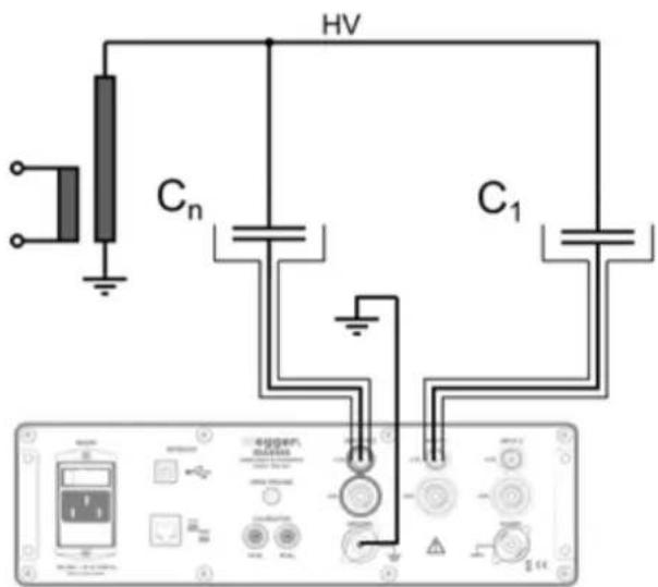
Figure 1. Capacitance measurement setup
10.1.1.1 Step-by-step instructions
- Before connecting the instrument, make sure that the high voltage generator is de-energized and that all parts of the test circuit are properly grounded.
• Referring to Figure 1, connect the instrument to:
○ Test ground, i.e. same grounding point as the test specimen.
○ A suitable AC power source.
○ The reference capacitor, Cn.
○ The test specimen.
- Set up the computer:
○ Connect the computer to the CDAX605 using a shielded Ethernet cable (or USB cable with ferrite choke).
- Run CDAX605 Control and connect to the instrument.
○ In the Settings tab, set the value of the reference capacitor (see figure below) and also configure the test specimen (press red, and/or blue, green).
- Return to Control tab
• Commence the measurement procedure:
○ Remove the high voltage side safety grounding.
- Carefully raise test voltage somewhat and check that the voltage reported by the instrument is as expected. Note that incorrect input of the reference capacitance value will lead to incorrectly reported voltage level, which may lead to excessive voltage levels.
○ Check that the continuously updated measurement results are as expected.
o Raise voltage to the specified test level.
o Press MEASURE. Results will be displayed

- Save, results will be stored in "results log". If "cancel", results are not stored
○ Perform additional measurements as required by pressing MEASURE again.
○ Lower the test voltage and turn of the generator.
- Disconnect the instrument in reverse order as during connection, i.e. de-energize and ground all parts of the circuit before disconnecting.
10.1.2 Ratio transformer with grounded HV supply
Calibrate/confirm the two reference components Cn and Cn1 (labeled C1 in Figure 1) by connecting them as in Figure 1 (section 10.1.1) and following the corresponding instruction. Note that the voltage handling capability of Cn1 might be limited.
- Without reconnecting:
○ Set up the software for ratio measurement, entering the calibrated values for Cn or Rn.

○ Measure the ratio and verify that it is exactly unity with zero phase shift.
- De-energize the high voltage generator and ground the setup.
- Connect the ratio transformer as in Figure 2.
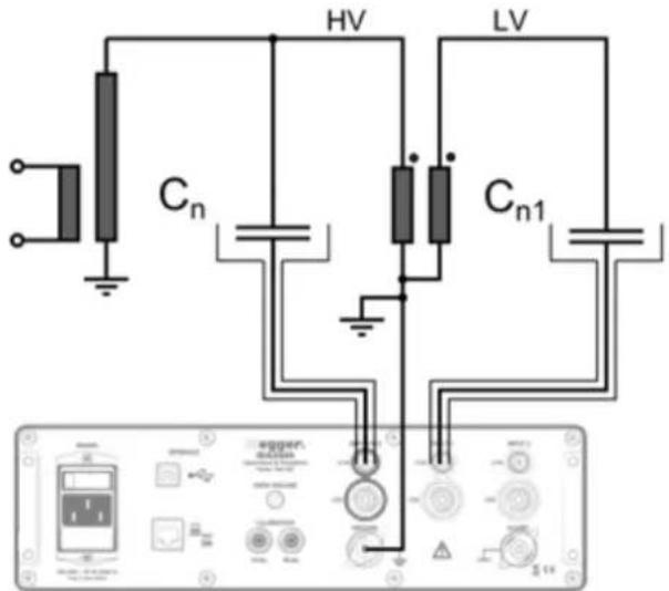
Figure 2. Ratio measurement setup
• Commence the measurement procedure:
- Remove the high voltage side safety grounding. - Carefully raise test voltage somewhat and check that the voltage reported by the instrument is as expected. Note that incorrect input of the reference capacitance value will lead to incorrectly reported voltage level, which may lead to excessive voltage levels.
○ Check that the continuously updated measurement results are as expected.
○ Raise voltage to the specified test level.
o Press MEASURE. Results will be displayed
○ Perform additional measurements as required by pressing MEASURE again.
○ Lower the test voltage and turn of the generator.
Ratio is calculated by the software using the current into the reference input, I_n, the current into the specimen input, I_x, and the values of Cn and Cn1 according to the following formula:
$$ N = \frac {I _ {n}}{I _ {x}} \cdot \frac {C _ {n 1}}{C _ {n}} $$
10.1.3 Grounded Specimen Test (GST) with floating HV Supply
This test mode enables the measurement of capacitances that are normally grounded on one side when in operation. When measuring transformers, this configuration measures the capacitance and dissipation factor between the HV winding and all other windings and the transformer housing.

Figure 3. Standard GST test circuit
Note: If a jumper is connected between ground and guard, it must be removed when performing GST measurements!
In the GST mode the inter-winding capacitance of the HV source will be added to the measurement and need to be as small as possible. Special double-shielded HV sources can be used to minimize this influence.
10.2 Measurements with Test Current greater than 5A (with external current transformer)
10.2.1 General information on Range Extension
When measuring large test object capacitances, the test current may exceeds the maximum permissible input current of CDAX (5A) and an external current transformer (current comparator) must be used for range extension.
When using an external CT for range extension, the accuracy of CDAX will be reduced by the inaccuracy of the CT. In addition, additional errors may occur depending upon the test mode applied.
10.2.2 Errors caused by an external CT
10.2.2.1 Correction formulas for tan δ and capacitance
10.2.2.1.1 Influence of the CT ratio accuracy
The ratio error mainly influences the capacitance measurement and the correction is performed according to the following formula:
$$ \mathrm{Ccorr} = \mathrm{Cmeas} ^ {*} (1 + \text {ratio error} (\% / 100) $$
The polarity of the current inaccuracy must be considered.
10.2.2.1.2 Influence of the CT phase accuracy
The error angle influences the dissipation factor measurement and the effective measured value of dissipation factor is calculated according to the following formula:
tanδcorr = tanδmeas + phase accuracy (minutes)/3440
Example:
A conventional current transformer (comparator) of Class 0.1 has the following accuracy:
Phase accuracy: ± 1 Minute
Ratio error: ± 0,1%
Measured values: Cx = 100nF , tan = 1e - 3
From the formulas given above, capacitance reading should be corrected by 0.1% and by 3e-4.
11 Stored data and reporting
Results are always stored by date and time in *.txt log files (default in directory My documents\CDAX605). A new log file is created every time the SW is started.
Results can also be stored by using the “Export” function in the results log tab. Measurement data as displayed in the table will be stored as a *.csv file in the selected directory. “Clear” is deleting data from the table for e.g. starting a new measurement session to be exported as a new file. Note: “Clear” will only clear the displayed data and not delete any data from the log file.
Reporting can be done in e.g. Excel by opening/importing exported data, importing a log file or by cut-and-paste data directly from the results log table.
12 User fields
User fields present a way for the user to customize the measurement results of the CDAX605 software. By defining statistical constraints on a measured parameter as defined by a user field, the risk of taking bad measurements due to measurement noise or drift lessens. In order to use user fields, the Results Window checkbox in the settings tab has to be checked. A measurement dialog will then popup each time the user presses the MEASURE button.
12.1 Editing user fields
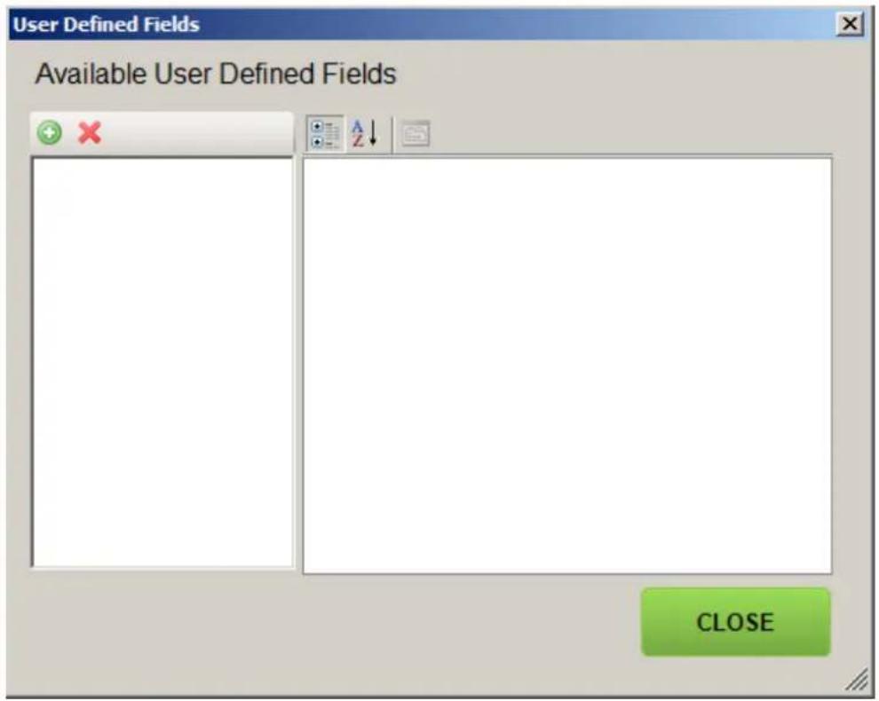
12.1.1 Description of buttons

Add user field
This button adds a new user field to the list. The field is given the default name of "Unnamed".

Remove user field
This button removes the selected user field.
12.1.2 User field parameters
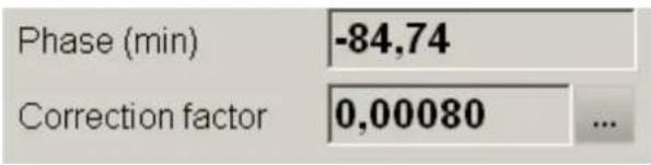
When selecting a user field, one will be shown a list of its parameters. The following picture shows the parameters of a user field called “Correction factor”:
| Misc | |
| AppendToLog | True |
| EnableRequirements | True |
| Format | F5 |
| Formula | result1_value/nomrat |
| Input | False |
| Name | Correction factor |
| Requirements | Requirements |
| Capacitance | False |
| RatioTransformerCapacitance | True |
| RatioTransformerResistance | True |
| Resistance | False |
| SignificantDigits | 4 |
| Statistics | Statistics |
| DataCount | 5 |
| Slope | 0 |
| StandardDeviation | 0 |
| TimeoutSeconds | 0 |
| Unit | |
| Value | 1.00062 |
| Variable | |
Listed below are the User Field parameters.
| Parameter name | Value | Description |
| AppendToLog | True/False | True if user field should be included in the log |
| EnableRequirements | True/False | True if the parameter should only be shown if specified Requirements are met. |
| Format | See http://en.csharp-online.net/CSharp_Format_Specifiers%E2%80%94Numeric_Format_Specifiers | Speficies how the numerical result should be presented, i.e. number of decimals etc. If this parameter if left empty the format will be specified instead by SignificantDigits, see below! |
| Formula | Valid mathematical expression, see separate section below. | States the formula to use in order to calculate the sought result. |
| Input | True/False | If True the user is prompted for the value during the measurement and it is treated as an input variable instead. An example could be Nominal ratio. |
| Name | Text string | The name of the User Field. |
| Requirements/Capacitance | True/False | If True this user field is only shown during measurement of capacitive type specimens |
| Requirements/Ratio TransformerCapacitance | True/False | If True this user field is only shown during measurement of ratio and if using a capacitive reference component on the secondary |
| Requirements/Ratios TransformerResistance | True/False | If True this user field is only shown during measurement of ratio and if using a resistive reference component on the secondary |
| Requirements/Resistance | True/False | If True this user field is only shown during measurement of resistive type specimens |
| SignificantDigits | Positive integer larger than zero. | The number of significant digits to show. Only used if Format is left blank. |
| Statistics/DataCount | Non-negative integer. | Minimum number of data points required. |
| Statistics/Slope | Positive numerical value or zero. | The maximum allowed “slope” of the collected data points. Not valid for single data point measurements. Slope is defined as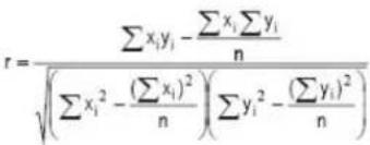 , where r is the slope, are the data points and are the corresponding sequence number, i.e. 1,2,3,4 ... n is the number of measurements , where r is the slope, are the data points and are the corresponding sequence number, i.e. 1,2,3,4 ... n is the number of measurements |
| Statistics/StandardDeviation | Positive numerical value or zero. | The maximum allowed standard deviation of the measured data. |
| Statistics/TimeoutSeconds | Positive numerical value or zero. | The maximum allowed time to collect measurement data points before timing out. |
| Unit | Character string. | The unit which to append the result. |
| Value | - | The immediate value of the user field, do not edit. |
| Variable | Either a valid variable name (containing the characters [a-z], [A-Z], [0-9] and ‘_’) or left empty. | The variable name to use if the Input parameter is True. |
12.1.3 Entering a formula
The formula can contain all standard operators: +, -, /, ^.
Predefined constants are:
• The eulerian number with: e = 2.718281828459045235360287
• Pi with pi = 3.141592653589793238462643
• The imaginary unit with: i = sqrt(-1)
The following postfix operators can be used: {n}, {mu}, {m}, {k}, {G}, {M}.
Standard functions: abs, sin, cos, tan, sinh, cosh, tanh, ln, log, log10, exp, sqrt
Complex functions: real, imag, conj, arg, norm
Predefined variables are:
| Variable name | Description |
| freq | frequency |
| hv_u | high side voltage |
| amxr_shunt | gain setting of reference input |
| amxx_shunt | gain setting of specimen input |
| amxr_i | input current into reference input |
| amxx_i | input current into specimen input |
| amxr_u | reference current amplifier output |
| amxx_u | specimen current amplifier output |
| amxg_uin | voltage from guard to ground |
| amxr_uin | voltage from guard to reference input |
| amxx_uin | voltage from guard to specimen input |
| result1_value | primary result, i.e. capacitance for capacitance measurements, resistance for resistance measurements or ratio for ratio measurements. |
| result2_value | secondary result. It is always equal to loss angle for capacitance measurements, impedance phase angle for resistance measurements and phase shift for ratio measurements. All angles are in radians. |
12.1.4 Example – Creating a user field showing correction factor
First we need to prompt the user for the nominal ratio (which is not known by the software).
- Press the button.
- Edit the Name parameter of the field so that it reads "Nominal ratio".
- Remove the contents of the "Formula" parameter.
- Set AppendToLog to True.
- Set Input to True so that the user will be prompted to enter the value.
- Set the parameter “Variable” to “nomrat”. This is the new variable name of the nominal ratio.
Now we need to add the actual user field which shows correction factor.
- Press the button.
- Edit the Name parameter of the field so that it reads "Correction factor".
- Edit the contents of the "Formula" parameter so that it reads "result1_value/nomrat". This is how the correction factor is calculated. "result1_value" corresponds to the primary measurement result, in this case the ratio.
- Set the Format parameter to "F5". This means fixed precision presentation with 5 digits after the decimal separator.
- Set AppendToLog to True.
- Set EnableRequirements to True.
- Under Requirements, set the parameters RatioTransformerCapacitance and RatioTransformerResistance to True. The rest of the requirement parameters should be False. This is so that the result shall only show up when measuring ratio and not, for example, capacitance.
- Under Statistics, set the DataCount parameter to 5 in order to make the instrument calculate the mean result from 5 consecutive measurements.
Now we are done. Press CLOSE. Check the Results Window checkbox in the settings tab in order to test the new user fields. Perform a ratio measurement and check that it works.
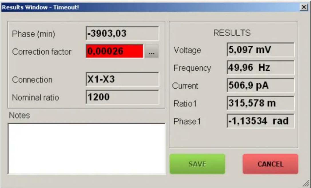
12.2 The Results Window
- The Results Window pops up when the user presses MEASURE, if the checkbox “Results Window” is checked in the Settings tab.
- If any user fields are defined with the parameter Input set to True, the user will be prompted to enter those values first.
- The Results Window shows the standard results plus any additional user fields defined by the user. If any of the user fields has a Statistics parameter defined (non zero) there will be a button next to it as in the following picture:
By pressing the *** button, a graph will popup showing the acquired data points and the corresponding statistical parameters. These are the same parameters as can be referred to using the Statistics/DataCount, Statistics/Slope or Statistics/StandardDeviation parameters of the user field.
By using the button after a measurement one can get a feel of the stability and noise of the measured parameters and also see which values are appropriate to use as constraints under the Statistics section of the user field in order for the measurement to be regarded as valid.

line
| Statistic | Value | | --------- | ----- | | Slope | 2.28465749260668E-05 | | StdDev | 0.000109023611048825 | | Data | 10 |Note!
The slope parameter does not reflect the measured data variation over time, but rather over the number of measurements – I.e. doubling the integration time per data point will thus halve the slope.
If, during a measurement, the statistical requirements upon a user field are not met within the specified Statistics/Timeout period, the user field will become red. It will also not be possible to save the measurement to the log.
- TRADEMARK NOTICES
- Content
- Overview
- General
- Measurement principle
- Specification
- Safety
- General
- IMPORTANT
- Instrument symbols
- Warning and Caution Notices
- Warning
- Caution
- General safety information
- Instrument safety
- Maintenance
- Warranty
- Receiving Instructions
- Warranty
- Warranty repair
- Control, indicators and connectors
- Front panel
- Software Installation
- CDAX605 Control
- Connect
- Control tab
- Settings tab
- Calibration
- Warm-up
- Calibration procedure
- Calibration
- Balancing
- Operating instructions
- Standard test circuits
- Ungrounded Specimen Test (UST) with grounded HV Supply
- Step-by-step instructions
- Ratio transformer with grounded HV supply
- Grounded Specimen Test (GST) with floating HV Supply
- Measurements with Test Current greater than 5A (with external current transformer)
- General information on Range Extension
- Errors caused by an external CT
- Correction formulas for tan δ and capacitance
- Influence of the CT ratio accuracy
- Influence of the CT phase accuracy
- Stored data and reporting
- User fields
- Editing user fields
- Description of buttons
- Add user field
- Remove user field
- User field parameters
- Entering a formula
- Example – Creating a user field showing correction factor
- The Results Window
- Note!
Brand : Megger
Model : CDAX 605
Category : Measurement